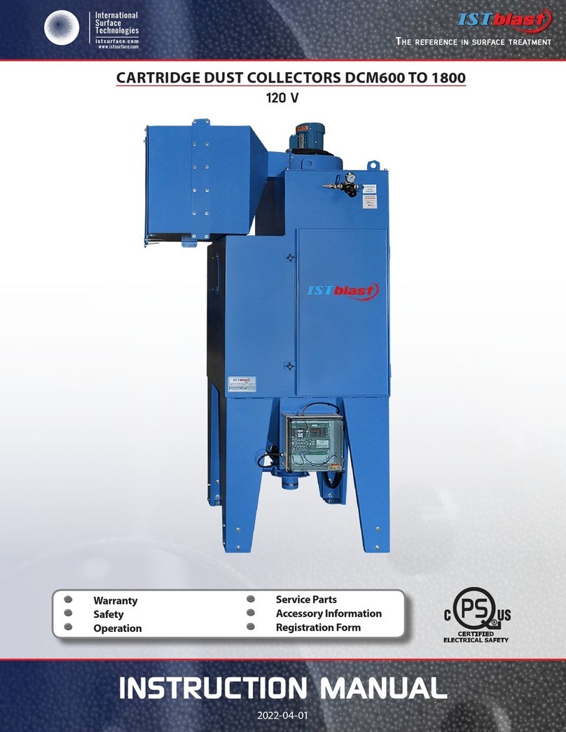
ISTblast AIRWALL 16000 User manual

InstructIon manual
2018-05-07
T
he
reference
in
surface
TreaTmenT
International
Surface
T
echnologies
istsurface.com
DUST COLLECTOR
TYPE AIRWALL 16000
Warranty
Safety
Operation
Service Parts
Accessory Information
Registration Form

T
he
reference
in
surface
TreaTmenT
International
Surface
T
echnologies
istsurface.com
2
AW16000 - Instruction Manual
ISTBLAST LIMITED WARRANTY ......................................................................................................................................................................... 3
NOTICE TO PURCHASERS AND USERS OF OUR PRODUCTS AND THIS INFORMATIONAL MATERIAL.................................. 4
DANGER AND WARNING LABELS..................................................................................................................................................................... 5
GENERAL SAFETY RULES PERSONAL SAFETY UNIT USE AND CARE............................................................................................ 6
INTRODUCTION INSTALLATION..................................................................................................................................................................... 7
SAFETY AND WARNING ....................................................................................................................................................................................... 8
GENERAL DESCRIPTION SET UP & INSTALLATION.................................................................................................................................. 9
SET UP & INSTALLATION CONT’D OPERATION...................................................................................................................................... 10
INITIAL STARTUP................................................................................................................................................................................................... 11
PREVENTIVE MAINTENANCE SERVICE MAINTENANCE REPLACING FILTER CARTRIDGES
........................................................... 12
SEASONING CARTRIDGES AUTOMATIC CARTRIDGE CLEANING TROUBLESHOOTING....................................................... 13
TROUBLESHOOTING CONT’D...................................................................................................................................................................... 14
FRONT VIEW............................................................................................................................................................................................................ 15
RIGHT SIDE VIEW................................................................................................................................................................................................... 16
LEFT SIDE VIEW...................................................................................................................................................................................................... 17
REAR VIEW............................................................................................................................................................................................................... 18
TOP & INTERIOR VIEW........................................................................................................................................................................................ 19
ELECTRICAL DETAILS .......................................................................................................................................................................................... 20
ELECTRICAL DETAILS PARTS LIST............................................................................................................................................................... 21
PARTS LIST CONT’D .......................................................................................................................................................................................... 22
TIMER CONTROLLER SYSTEM.......................................................................................................................................................................... 23
SERIES DCT1000 DUST COLLECTOR TIMER CONTROLLER................................................................................................................... 24
SPECIFICATIONS INSTALLATION AND OPERATING INSTRUCTIONS............................................................................................. 24
SERIES DCT1000 DUST COLLECTOR TIMER CONTROLLER CONT’D .............................................................................................. 25
DIMENSIONAL SPECIFICATIONS .................................................................................................................................................................... 25
1.0 INSTALLING THE DCT1000................................................................................................................................. ..................................25 to 31
2.0 PROGRAMMING THE DCT1000 MASTER CONTROLLER........................................................................................................... 31
2.0 PROGRAMMING THE DCT1000 MASTER CONTROLLER........................................................................................................... 32
3.0 MAINTENANCE SUPPORT AND DIAGNOSTICS...................................................................................................................................33, 34
4.0 GLOSSARY OF TERMS............................................................................................................................................................................. 35
SERIES DCP100A/200A PRESSURE MODULES........................................................................................................................................... 36
SPECIFICATIONS INSTALLATION & OPERATING INSTRUCTIONS ................................................................................................... 36
SERIES DCP100A/200A PRESSURE MODULESCONT’D ....................................................................................................................... 37
SPECIFICATIONS INSTALLATION & OPERATING INSTRUCTIONS ................................................................................................... 37
SERIES DCP100A/200A PRESSURE MODULES........................................................................................................................................... 38
SPECIFICATIONS INSTALLATION & OPERATING INSTRUCTIONS ................................................................................................... 38
MANIFOLD WELDING & ASS’Y SCHEMATIC............................................................................................................................................. 39
ELECTRICAL SCHEMATIC................................................................................................................................................................................... 40
WARRANTY INFORMATION / TECHNICAL ASSISTANCE ........................................................................................................................ 41
ISTBLAST WARRANTY REGISTRATION.......................................................................................................................................................... 42
TABLE OF CONTENTS
Page

T
he
reference
in
surface
TreaTmenT
International
Surface
T
echnologies
istsurface.com
3
AW16000 - Instruction Manual
1. Carefully inspect the shipping carton for any signs of transport damage.The damage to the carton often
indicates possibility of transport damage to the equipment inside.
2. Carefully remove your ISTblast SANDBLASTING CABINET from the shipping carton and skid.
3. Check your equipment immediately to ensure that it is free of transport damage. Report any transport
damage to the carrier without delay for possible claim procedures. International Surface Technologies
inc. is not responsible for damage to equipment after it leaves our warehouse.
4. Check the equipment zx and compare it with the parts you have received. If any parts are missing,
contact the supplier you purchased the equipment from.
Before operating the ISTblast SANDBLASTING CABINET, read this Instruction Manual completely. All
ISTblast products are engineered and manufactured to the highest performance standards and have
been subjected to detail testing before shipment from the factory.
NOTICE TO PURCHASERS AND USERS OF OUR PRODUCTS AND THIS INFORMATIONAL
MATERIAL
Welcome to the ISTblast ® family of sandblasting products.This booklet contains helpful information
and acquaints you with the operation and maintenance of your equipment. Please read carefully
and follow our recommendations to assure trouble free operation. If you have any questions, please
do not hesitate to contact your distributor or our technical service.
Page

T
he
reference
in
surface
TreaTmenT
International
Surface
T
echnologies
istsurface.com
4
AW16000 - Instruction Manual
INTRODUCTION INSTALLATION
The products described in this material, and the information relating to those products, is intended for
knowledgeable, experienced users of abrasive blasting equipment.
No representation is intended or made as to the suitability of the products described herein for any particular
purpose of application. No representations are intended or made as to the eciency, production rate, or the
useful life of the products described herein.
Any estimate regarding production rates or production nishes are the responsibility of the user and must
be derived solely from the user’s experience and expertise, and must not be based on information in this
material.
The products described in this material may be combined by the user in a variety of ways for purposes
determined solely by the user. No representations are intended or made as to the suitability or engineering
balance of the combination of products determined by the user in his selection, nor as to the compliance
with regulations or standard practice of such combinations of components or products.
It is the responsibility of the knowledgeable, experienced users of the products mentioned in this material to
familiarize themselves with the appropriate laws, regulations and safe practices that apply to these products,
equipment that is connected to these products and materials that may be used with these products.
It is the responsibility of the user to insure that proper training of operators has been performed and a safe
work environment is provided.
Our company is proud to provide a variety of products to the abrasive blasting industry, and we have
condence that the professionals in our industry will utilize their knowledge and expertise in the safe
ecient use of these products.

T
he
reference
in
surface
TreaTmenT
International
Surface
T
echnologies
istsurface.com
5
AW16000 - Instruction Manual
GENERAL SAFETY RULES PERSONALSAFETY UNIT USE AND CARE
PERSONAL SAFETY
UNIT USE AND CARE
• KEEP WORK AREA CLEAN.
• KEEP CHILDREN AWAY. Do not let visitors come in contact with the equipment. All visitors should
be kept away from the work area.
•GUARD AGAINST ELECTRIC SHOCK. Non-skid footwear is recommended where damp or wet ground
may be encountered. A ground fault circuit interrupter protected power line must be used for these
conditions.
•DRESS PROPERLY. Do not wear loose clothing or jewelry. They can be caught in the moving parts. Wear
protective hair covering to contain long hair.
•USE SAFETY EQUIPMENT. WEAR SAFETY GOGGLES or glasses with side shields.
•WEAR A DUST PROOF MASK.
•STAY ALERT. USE YOUR COMMON SENSE. Concentrate on what you are doing. Do not operate the unit
when you are tired or under the inuence of drugs.
•DO NOT OVERREACH. Keep proper footing and balance at all times.
•BEFORE CONNECTING THE UNIT be sure the power is the same as that specied on the nameplate of
the Sand Blasting Cabinet.With power greater than that specied on the Nameplate can seriously injure
the user – as well as damage the Unit.
•DO NOT FORCE THE UNIT. It will perform better and safer at the rate for which it was designed.
•THE USE OF ANY OTHER ACCESSORIES not specied in this manual may create a hazard.
•CLOSE THE MAIN BREAKER SWITCH BEFORE SERVICING or when not in use.
•DO NOT ALTER OR MISUSE THE UNIT. These units are precision built. Any alteration or modication not
specied is misuse and may result in a dangerous situation.
Only trained repairmen should attempt (•) ALL REPAIRS, electrical or mechanical. Contact the nearest
ISTblast a repair service facility. Use only ISTblast replacement parts; any other parts may create a
hazard.
WARNING
« READ ALL INSTRUCTIONS » Failure to follow the SAFETY RULES identied by a BULLET (•) symbol listed
BELOW and other safety precautions may result in serious personal injury.
« SAVE THESE INSTRUCTIONS »

T
he
reference
in
surface
TreaTmenT
International
Surface
T
echnologies
istsurface.com
6
AW16000 - Instruction Manual
Dust Collectors are dry, reverse pulse jet cartridge collectors, used to ventilate abrasive blast cabinets and remove
dust from exhausting air.
The exhauster is mounted on the clean-air side of the filter cartridges, and provides «pull-through» (pulls air
through the reclaimer) air flow rated at 600 to 1800 cfm depending on the exhauster size. Dust and particles are
drawn through the reclaimer into the dust collector, trapping dust before discharging clean air.
Filter cartridges are cleaned by a pulse of high velocity compressed air expanding against the inner surface of
the cartridges. The expanding air momentarily reverses air flow through the cartridge, releasing dust that has
accumulated on the outer surface. The dust particles fall away from the cartridges and into the dust drawer.
The pulse interval are controlled by a sequencer located in front of the dust in the plastic electrical box. The timer
controls the «on» time (the length of time for each pulse) and «off» time (the length of time between each pulse).
The «on» time should never be adjusted. The lower the setting for the «off» time, the shorter the length of time
between pulses.
CAUTION : do not pulse new dust collectors or replacement cartridges until the cartridges are
properly seasoned. See page 13 pulsing unseasoned cartridges could cause premature cartridge
failure or decrease the efficiency of dust collector.
The differential pressure gauge shows the pressure difference between the dust side and clean side of the
cartridges. The led indicator helps determine the proper pulse pressure and timer «off» time setting. See page 11.
Position the collector in a convenient location that complies with OSHA and local safety codes. Allow access to
the differential pressure sequencer and exhaust damper. Provide ample space at the top and at the front to open
the cover to access pulsating air jet system and the cartridges.
Shorting electrical components could result in serious electrical shocks, or equipment damage. All
electrical work must be performed by a qualified electrician, and comply with applicable codes.
Connect electrical power
NOTE : A schematic for ISTblast cabinets is supplied with the cabinet. After wiring completed, keep the schematics
and manuals together for future reference and electrical replacement parts. Wiring from the user’s disconnect
to the cabinet controls must be provided by the user. Conduit and wiring from the control box (or starter) to the
exhauster motor and 115 volts to the RPC Control Panel (Pulse Sequence Panel), must also be provided by the
user. If the dust Collector replaces an existing «push through» collector or dust bag, the exhauster may be wired
into the control box, to the terminal strip or starter where the conduit from the old reclaimer motor is attached.
Electrical requirements depend on the size and phase of the motor. Standard dust collectors are supplied as
follows:
16000 CFM collectors, 7.5 hp, 230/450 V, 3 Ph, 60 Hz.
WARNING : Electrical power must be locked out and tagged out before continuing.
GENERAL DESCRIPTION SET UP & INSTALLATION
SET UP & INSTALLATION

T
he
reference
in
surface
TreaTmenT
International
Surface
T
echnologies
istsurface.com
7
AW16000 - Instruction Manual
Install conduit, and wire the exhauster motor per instruction on the motor plate, and the motor starter (for 3 PH
wiring), or terminal strip (for 1 PH wiring) as shown on the schematic.
Install conduit, and wire 115 volt power to the reverse pulse control panel as shown on the schematic.
After the wiring is completed, observe the subsequent warning, and check the motor rotation. To check rotation,
jog the starter (momentarily turn switch on and off). This will cause the motor to rotate slowly. Look through the
slots in the fan housing on top of the motor where rotation of the fan can easily be observed. Proper rotation is
indicated by the arrow on the exhauster housing. The fan should rotate toward the exhauster outlet
WARNING : do not look into the exhauster outlet while the paddle wheel is turning.
Injury to the eye or face could occur from objects being ejected from the exhauster.
Check the amperage on initial start up. If the motor draws excessive amperage, gradually close the damper until
the amperage is within the specifications shown on the motor plate. The damper is located on the exhauster
outlet. Ground Dust Collector
To prevent static electricity build up, attach an external grounded wire from an earth ground to the grounding
lug located on the rear wall of the dust collector.
Compressed Air Connections
NOTE: For maximum filter life and efficiency, the pulse air source should be 30% relative humidity or less, and be
free of any oil contaminants. If line air does not meet this requirement, an air dryer is recommended.
Connect a 1» or larger air hose to the pressure regulator located (Picture C, page 17) on the pulse manifold inlet.
An isolation valve should be installed at the air source to enable depressurization for service. If rigid pipe is used
for the air line, a flexible section of hose must be used at the connection, to enable the top access door to swing
open for service.
WARNING if twist-on type air hose couplings are used, they must be secured by safety pins or wires to prevent
accidental disconnection while under pressure. Hose disconnection while under pressure could cause serious
injury.
WARNING all persons operating this equipment must be made aware of the hazards
of abrasive blasting. Prolonged exposure to any dust could result in serious lung
disease and death. Short term ingestion of toxic materials, such as lead dust or dust
from other heavy metals and corrosives, could cause serious respiratory injury or
death. Identify all materials that are to be removed by blasting, and obtain a Materials
Safety Data Sheet (MSDS) for the blast media. If lead coating or other toxic materials
are being removed by the blasting process, HEPA after-filters must be used for those
applications.
SET UP & INSTALLATION CONT’D OPERATION

T
he
reference
in
surface
TreaTmenT
International
Surface
T
echnologies
istsurface.com
8
AW16000 - Instruction Manual
The dust collector access doors and dust drawer on the reclaimer must be closed when the dust collector is on.
CAUTION : do not pulse new dust collectors or replacement cartridges until the cartridges are properly seasoned.
Pulsing unseasoned cartridges could cause premature cartridge failure or decrease the efficiency of dust collector.
Start-Up
Check that front access door is secured with knob, and that the dust drawer is closed with latch.
Check that the sequence switch is on.
NOTE: Do not turn the sequence switch «on» until the cartridges are properly seasoned, page 13
Start the exhauster at the control panel, usually mounted on the blast cabinet. Check the pulse manifold pressure.
Shutdown
Run the collector until all media is recovered from the cabinet, and the cabinet is free of airborne dust.
Turn off the exhauster.
Turn off the compressed air supply valve.
Drain the pulse manifold whenever the compressed air supply is turned off. The drain petcock is mounted on the
side of the collector.
Empty contents from the dust drawer into a suitable container, per Section maintenance for dust drum page__
Manifold Pressure Module
The pressure regulator located on the pulse manifold inlet, adjust pulse pressure. Set initial pressure at 70 psi.
Pulse Sequence Control Panel
Your dust collector is equipped with an automatic cartridges cleaning system. You can see the condition of the
cartridges with the digital reader.
Pulse Sequence Control set up parameters
This module is controlled; it means you can change the parameters for maximum cartridges efficiency. Refer to DCT
1000
With key button (select) and (up) (down), you can change some parameters.
Your equipment is already factory set, before changing any parameters, take note of the initial parameters.
Parameters:
Process : ....................Value shown wile blower is running (inch of water, cartridges restriction)
Last Output : ........... Number of active solenoid (this value can not be change, system will detect
automatically the number of solenoid connected to the control card)
Time Off: ................ laps of time between each pulsation (value 10 seconds)
Time ON: ...................Valve pulsating time (250 msec value)
High Limit: ...............Value to which cleaning will start (value between 2.5 and 3.5)
Low limit: .................Value to which cleaning will stop automatically (value between 2.5 and 3.5)
High Alarm: .............Value to be reached to activate Alarm (value High limit +2)
Low Alarm: ............. Value having to be reached to activate Alarm (value =0)
Cycle Delay: .............This value is for manual mode (value= 0)
Down time cycles: .This value is for manual mode (value= 0)
Auto Alarm reset: ..This value is for manual mode (value= 0)
INITIAL STARTUP
ADJUSTMENTS

T
he
reference
in
surface
TreaTmenT
International
Surface
T
echnologies
istsurface.com
9
AW16000 - Instruction Manual
Always wear a properly fitted and maintained, CSA, OSHA or NIOSH approved respirator and eye
protection when emptying the dust drawer. Failure to do so could result in respiratory disease or
serious respiratory and eye irritation. Toxicity and health risk vary with type of media, and dust
generated by blasting. Identify all material that is being removed by blasting, and obtain a Materials
Safety Data Sheet for the blast media.
Weekly
With the exhauster turned off, check the in-line dust filter dust accumulation. Check the exhaust air during a pulse
cycle. If dust is emitting from the exhauster, cartridges are leaking or damaged. Check immediately
With the exhauster turned off, empty the dust barrel. Heavily contaminated parts or friable media may require the
drawer be emptied more often. Never allow the drawer to become more than a quarter full.
WARNING All maintenance must be done with the electrical power locked-out and tagged-out, and
the compressed air supply line bled, locked-out and tagged-out. Failure to do so could result in death
or serious injury from electrical shock, unintentional actuation of a component, or from the venting of
trapped compressed air.
WARNING : Failure to wear properly tted and maintained, CSA, OSHA or NIOSH
approved respirator and eye protection when servicing dust laden areas of the dust
collector could result in serious eye irritation and lung disease or death. Toxicity and
health risk vary with type of media, and dust generated by blasting. Identify all material
that is being removed by blasting, and obtain a Materials Safety Data Sheet for the blast
media.
Empty the dust drum.
Open the front access door.
Remove the cartridges from the front access door . A small amount of force may be necessary to loosen the seal
of the cartridge gasket.
When cartridges are removed, clean the inside of the collector to remove loose or hardened dust, particularly
from the cartridge sealing surface, and the clean side (top side) of the cartridge sheet.
Install new cartridges; center each cartridge, install back the cartridge spacer and turn the locking to assure a
proper seal.
Inspect the access door gasket, replace if worn or damaged. Close the access door and secure.
PREVENTIVE MAINTENANCE
SERVICE MAINTENANCE
REPLACING FILTER CARTRIDGES

T
he
reference
in
surface
TreaTmenT
International
Surface
T
echnologies
istsurface.com
10
AW16000 - Instruction Manual
New cartridges must be seasoned. Cartridges are seasoned by letting a dust layer develop on the outside surface
of the filter media. The dust layer protects the filter cartridge, and enhances the filtering efficiency.
Cleaning will be done automatically. When differential static pressure indicator (parameter section high alarm,
page 11) indicates high-pressure alarm, the high alarm signal will blink. Cartridges need to be replaced at that time
WARNING : shut down the collector immediately if dust is emitting from the exhauster.
Check that cartridges are correctly seated and not worn or damaged. Prolonged breathing of
abrasive dust and blasting by-product dust could result in serious lung disease or death. Short
term ingestion of toxic dust such as red lead, poses an immediate danger to health. Identify all
materials that are to be removed by blasting, and obtain a Materials Safety Data Sheet for the
blast media.
Collector Not Pulsing
® Check the manifold pressure gauge. If the reading is low, check the regulator adjustment,
and compressed air supply, look for a closed supply valve.
® Check to make sure the sequence switch is energized.
® Check that the pulse system program as not been change.
® Check the fuse in the main electrical box. Replace as necessary.
One Cartridge Not Pulsing
® Solenoid is defective. Check continuity for electrical malfunction.
® Check the diaphragm valve. With the compressed air turned off, remove the cover screws, inspect the
diaphragm and clean the bleed port.
® Check for blockage in the tubing to the diaphragm valves.
Pulse is a steady stream of air instead of a pulse.
® Check for a leak in the tubing between the diaphragm valves and solenoid.
® Solenoid is remaining in open position. Check continuity, clean, replace.
Exhauster Not Running
® Exhauster overload could be tripped. Reset and check for overload.
® Make sure that the main disconnect is «on».
® Motor is defective. Check continuity.
SEASONING CARTRIDGES
AUTOMATIC CARTRIDGE CLEANING
TROUBLESHOOTING

T
he
reference
in
surface
TreaTmenT
International
Surface
T
echnologies
istsurface.com
11
AW16000 - Instruction Manual
TROUBLESHOOTING CONT’D
Excessive Differential Pressure
® Valves may not be pulsing properly.
® The differential pressure gauge lines may be plugged with dust. Check and clean.
® Make sure the tubing has not been inserted so far into the tube connection that it blocks the tube ends.
The in-line dust filter may be blocked. Clean or replace.
® Snubbed fittings blocked with dust. Clean or replace.
No Reading on Differential Pressure Gauge.
® Check to make sure the low and high pressure lines have not been reversed.
® Check that the exhauster is running.
Dust is Emitting from Exhauster.
® Check for loose or damaged filter cartridge.

T
he
reference
in
surface
TreaTmenT
International
Surface
T
echnologies
istsurface.com
12
AW16000 - Instruction Manual
A
1
1
2
electrical
panel
see. fig. G
FRONT VIEW

T
he
reference
in
surface
TreaTmenT
International
Surface
T
echnologies
istsurface.com
13
AW16000 - Instruction Manual
RIGHT SIDE VIEW
B
10
4
5
9
3
2
17
8
6

T
he
reference
in
surface
TreaTmenT
International
Surface
T
echnologies
istsurface.com
14
AW16000 - Instruction Manual
LEFT SIDE VIEW
C
1

T
he
reference
in
surface
TreaTmenT
International
Surface
T
echnologies
istsurface.com
15
AW16000 - Instruction Manual
REAR VIEW
D
1

T
he
reference
in
surface
TreaTmenT
International
Surface
T
echnologies
istsurface.com
16
AW16000 - Instruction Manual
TOP & INTERIOR VIEW
Top
Interior
E
2
3
1
ELECTRICAL DETAILS

T
he
reference
in
surface
TreaTmenT
International
Surface
T
echnologies
istsurface.com
17
AW16000 - Instruction Manual
ELECTRICAL DETAILS
Connectors & cdes
Panel
F1
2
5
6
4
8
7
3
11
10
9
2
12

T
he
reference
in
surface
TreaTmenT
International
Surface
T
echnologies
istsurface.com
18
AW16000 - Instruction Manual
ELECTRICAL DETAILS PARTS LIST
# STOCK DESCRIPTION
1916163
BLOWER
2NPN
DUST DRAWER
36165725
MOTOR
# STOCK DESCRIPTION
1NPN
AIR INLET
# STOCK DESCRIPTION
1NPN
FOAM GASKET
# STOCK DESCRIPTION
1618054
STARTER WITH BUTTON
2617053
STARTER
3616572
ELECTRIC CABLE 14-3
4608568
SOLENOID
5616535
LIQUID TIGHT CABLE 3/8
# STOCK DESCRIPTION
6616534
LIQUID TIGHT 1/2’’
7616767
CONNECTOR 1/2’’ 90°
8616741
STRAIN RELIEF 2522
9616580
ELECTRIC CABLE 12-4
10
917799
OVERLOAD RELAY
617289
TIMER 24V
917497
TRANSFORMER 460/120-240 250VA
Figure A
Figure C
Figure B
Figure D

T
he
reference
in
surface
TreaTmenT
International
Surface
T
echnologies
istsurface.com
19
AW16000 - Instruction Manual
PARTS LIST CONT’D
Figure F
# STOCK DESCRIPTION
1324502
BULK HEAD PUSH IN
2324571
URETHANE HOSE 1/4’’
3324561
PUSH IN 1/8’’ NPT X 1/4’’
4N PN
‘‘ON’’ BUTTON
5NPN
‘‘OFF’’ BUTTON
6616741
STRAIN RELIEF 2522
# STOCK DESCRIPTION
7616770
CONNECTOR 3/8’’
8616742
STRAIN RELIEF 2525
9908704
PRESSURE MODULE DCP100
10 908702
TIMER CONTROLLER DCT1000
11 917474
BOX WITH COVER
12 616534
LIQUID TIGHT 1/2’’
# STOCK DESCRIPTION
1616572
MOTOR
2611056
MOTOR FILTER
# STOCK DESCRIPTION
3901348
CARTRIDGE
Figure E

T
he
reference
in
surface
TreaTmenT
International
Surface
T
echnologies
istsurface.com
20
AW16000 - Instruction Manual
TIMER CONTROLLER STSTEM
DCP 100
Pressure module
# 908704
DCT 100
Static pressure
indicator
DCT 1000
Sequencer
# 908702
Table of contents
Other ISTblast Dust Collector manuals
Popular Dust Collector manuals by other brands

Grizzly
Grizzly G0672 owner's manual

Exmark
Exmark Quest 126-7510 manual

King Canada
King Canada KC-1105C instruction manual

Jet
Jet JDC-500B Operating instructions and parts manual

LNS
LNS FOX WS 2 170 Instruction and installation manual

Oneida Air Systems
Oneida Air Systems 5 & 7.5 HP Direct Drive Cyclonic Dust... owner's manual