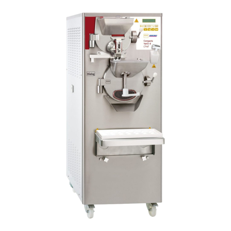
Italian Gelato CATTABRIGA MANTEMATIC K20S manual

INSTRUCTION HANDBOOK
MANTEMATIC K20S
APPLICARE
TARGA
CARATTERISTICHE
Italian Gelato Concepts Pty Limited
Unit 1, 37 Mortimer Road
Acacia Ridge Qld 4110
Bris Office: +61 (0) 7 3162 7724
Syd Office +61 (0) 2 8311 9701
Email: [email protected]
www.italiangelato.com.au

- 2 -
Mantematic K20S
Mantematic K20S_EN - 2010/04 - Ed. 01
Cattabriga
Via Emilia, 45/A - 40011 Anzola dell'Emilia (Bologna) - Italy
Tel. +39 051 - 6505330 Fax +39 051 - 6505331
This manual contains a TRANSLATION OF THE ORIGINAL INSTRUCTIONS and may not
be reproduced, transmitted, transcribed, filed in a data retrieval system or translated into other
languages, without the prior written permission of Cattabriga.
The purchaser has the wright to reprint it for his own office use.
Cattabriga policy pursues a steady reasearch and development, thus it reserves the right to make
changes and revisions whenever deemed necessary and without being bound to previous state-
ments to the purchaser.
We wish to thank you for the preference granted to us by purchasing one of
Cattabriga machines.
To the best guarantee, since 1993 CATTABRIGA has submitted its own Qual-
ity System to the certification according to the international Standard ISO 9001,
nowadaysitsproductionhasgotUNI-EN-ISO9001-2008CertifiedQualitySystem.
Moreover, CATTABRIGA machines comply with following European Direc-
tives:
• “Machinery” Directive 2006/42/EC,
• “Low Voltage” Directive 2006/95/EC,
• “EMC” Directive 2004/108/EC,
• “PED” Directive 97/23/EC,
• Regulation 2004/1935/EC relating to “Materials and articles in contact with
foodstuffs”.
Issue: 01 Date: 2010/04 Changes:
Issued by: AM Checked by: PB Approved by: RV

Mantematic K20S
- 3 - Mantematic K20S_EN - 2010/04- Ed. 01
GENERAL INDEX
FOREWORD....................................................................................................................... 5
INSTRUCTION HANDBOOK................................................................................. 5
PURPOSE.................................................................................................................. 5
HANDBOOK STRUCTURE .................................................................................... 5
ADDITIONAL DOCUMENTATION ....................................................................... 5
CONVENTIONAL SYMBOLS................................................................................ 6
SAFETY..................................................................................................................... 7
QUALIFICATION OF THE STAFF ......................................................................... 7
WARNING................................................................................................................. 7
SEC. 1 GENERAL INFORMATION
1.1 GENERAL INFORMATION ................................................................................. 9
1.1.1 MANUFACTURER'S IDENTIFICATION DATA......................................... 9
1.1.2 INFORMATION ABOUT SERVICE............................................................. 9
1.1.3 INFORMATION TO THE USER................................................................... 9
1.2 INFORMATION ABOUT MACHINE .................................................................. 9
1.2.1 GENERAL DATA........................................................................................... 9
1.2.2 TECHNICAL FEATURES........................................................................... 10
1.3.3 LOCATION OF MACHINE GROUPS.........................................................11
1.3 INTEDED USE........................................................................................................11
1.4 NOISE......................................................................................................................11
1.5 STORING A MACHINE........................................................................................11
1.6 DISPOSAL OF PACKING STUFFS.....................................................................11
1.7 WEEE (Waste Electrical and Electronic Equipment)........................................ 12
SEC. 2 INSTALLATION
2.1 ROOM NECESSARY TO THE MACHINE USE.............................................. 13
2.2 WATER SUPPLY CONNECTION....................................................................... 13
2.3 MACHINES WITH AIRCOOLED CONDENSER............................................ 13
2.4 MACHINES WITH WATERCOOLED CONDENSER..................................... 14
2.4.1 WATER VALVE ADJUSTMENT................................................................ 14
2.5 ELECTRIC CONNECTION................................................................................ 14
2.5.1 REPLACING THE POWER CABLE.......................................................... 14
2.6 LOCATION............................................................................................................ 15
2.7 REFILLING........................................................................................................... 15
2.8 MACHINE TESTING........................................................................................... 15
SEC. 3 DIRECTION FOR USE
3.1 MACHINE SAFETY WARNINGS ...................................................................... 17
3.2 MACHINE CONFIGURATION.......................................................................... 17
3.3 CONTROLS........................................................................................................... 18
3.4 ICE CREAM UNLOADING LID ........................................................................ 18
3.5 PUTTING THE MACHINE INTO OPERATION............................................. 19
SEC. 4 SAFETY DEVICES
4.1 FRONT LID MICROSWITCH............................................................................ 21

- 4 -
Mantematic K20S
Mantematic K20S_EN - 2010/04 - Ed. 01
SEC. 5 CLEANOUT DISASSEMBLINGAND REASSEMBLING
PARTS IN CONTACT WITH THE PRODUCT
5.1 MODALITA’ D’USO DETERGENTE/SANITIZZANTE XSAN.......................... 23
5.2 OUTSIDE CLEANOUT........................................................................................ 23
5.3 PRELIMINARY CLEANOUT............................................................................. 24
5.4 BEATER DISASSEMBLY.................................................................................... 24
5.4.1 STUFFING BOX.......................................................................................... 24
5.5 FRONT LID DISASSEMBLY.............................................................................. 25
5.5.1 ICE CREAM DOOR DISASSEMBLY........................................................ 25
5.5.2 HOPPER COVER DISASSEMBLY............................................................ 25
5.6 SANITIZATION.................................................................................................... 26
5.7 HYGIENE............................................................................................................... 26
SEC. 6 MAINTENANCE
6.1 SERVICING TYPOLOGY................................................................................... 27
6.2 WATERCOOLING................................................................................................ 27
6.3 AIRCOOLING....................................................................................................... 27
6.5 ORDERING SPARE PARTS................................................................................ 28
6.4 ACCESSORIES KIT............................................................................................. 28
SEC. 7 TROUBLESHOOT GUIDE..............................................................29

Mantematic K20S
- 5 - Mantematic K20S_EN - 2010/04- Ed. 01
FOREWORD
INSTRUCTION HANDBOOK
Editing this handbook, it was taken into due account European Community directions on safety
standards as well as on free circulation of industrial products within E.C.
PURPOSE
This handbook was conceived taking machine users' needs into due account.
Topics relevant to a correct use of the machine have been analyzed in order to keep unchanged in
the long run quality features charachterizing Cattabriga machines all over the world.
A significant part of this handbook refers to the conditions necessary to the machine use and to
the necessary procedure during cleanout as well as routine and special maintenance.
Nevertheless, this handbook cannot meet all demands in details. In case of doubts or missing
information, please apply to:
Cattabriga Via Emilia, 45/A - 40011Anzola dell'Emilia (Bologna) - Italy
Tel. +39 051 - 6505330 Fax +39 051 - 6505331
HANDBOOK STRUCTURE
This handbook is divided in sections, chapters and subchapters in order to be consulted more
easily.
Section
A section is the part of the handbook identifying a specific topic related to a machine part.
Chapter
A chapter is that part of a section describing an assembly or concept relevant to a machine part.
Subchapter
It is that part of a chapter detailing the specific component of a machine part.
It is necessary that each person involved in the machine operation reads and clearly under-
stands those parts of the handbook of his/her own concern, and particularly:
•The Operator must read the chapters concerning the machine star-up and the operation of
machine components.
•Askilled technicianinvolved in theinstallation, maintenance, repair, etc.,of the machinemust
read all parts of this handbook.
ADDITIONAL DOCUMENTATION
Along with an instruction manual, each machine is supplied also with additional documenta-
tion:
•Part list: a list of spare parts which is delivered together with the machine for its mainte-
nance.
•Wiring diagram: a diagram of wiring connections is placed in the machine.
Before using the machine read carefully the instruction handbook.
Pay attention to the safety instructions.

- 6 -
Mantematic K20S
Mantematic K20S_EN - 2010/04 - Ed. 01
CONVENTIONAL SYMBOLS
CAUTION: ELECTRIC SHOCK DANGER
The staff involved is warned that the non-obsevance of safety rules in carrying out the operation
described may cause an electric shock.
CAUTION: GENERAL HAZARD
The staff involved is warned that the operation described may cause injury if not performed fol-
lowing safety rules.
NOTE
It points out significant information for the staff involved.
WARNINGS
The staff involved is warned that the non-observance of warning may cause loss of data and
damage to the machine.
PROTECTIONS
This symbol on the side means that the operator must use personal protection against an implicit
risk of accident.
Qualification of the staff
MACHINE OPERATOR
Identify unqualified personnel or personnel without specific abilities capable of carrying out
only simple duties such as: control of the machine via the use of controls on the selector switch,
loadingandunloadingoperationsof productsutilised duringproduction, elementarymaintenance
operations (cleaning, simple blocking of the machine, checking the instruments, etc.).
MAINTENANCE ENGINEER
He/she is a skilled engineer for the operation of the machine under normal conditions; he/she is
able to carry out interventions on mechanical parts and all adjustments, as well as maintenance
and repairs. He/she is qualified for interventions on electrical and refrigeration components.
CATTABRIGA ENGINEER
He/she is a skilled engineer the manufacturer assigned to field interventions for complex jobs
under particular conditions or in accordance with agreements made with the machine's owner.

Mantematic K20S
- 7 - Mantematic K20S_EN - 2010/04- Ed. 01
SAFETY
Whenusingindustrial equipmentandplants, one mustbe aware ofthefact thatdrivemechanisms
(rotarymotion), highvoltagecomponents,aswellasparts subjecttohightemperaturesmay cause
serious damage to persons and things.
Who is in charge of plant safety must be on the look-out that :
- An incorrect use or handling shall be avoided
- Safety device s must neither be removed nor tampered with
- The machine shall be regularly serviced
- Only original spare parts are to be used especially as far as those components with safety
functions are concerned (ex.: frontlid microswitch).
- That appropriate individual protection equipment is used.
To achieve the above, the following is necessary:
- At the working place an instruction manual relevant to the machine should be available.
- Such documentation must be carefully read and requirements must conse quently be met.
- Only adequately skilled personnel should be assigned to electrical equipment.
- Be on the look out that no technician will ever carry out interventions outside his own knowl-
edge and responsibility sphere.
QUALIFICATION OF THE STAFF
Staff attached to the machine can be distinguished according to training and responsibility as fol-
lows:
OPERATOR
- A person who has not necessarily a high technical knowledge, just trained for ordinary op-
eration of the machine, such as: startup, stop, filling, basic maintenance (cleaning, simple
blocking of the machine, general checks, etc.).
SKILLED ENGINEER
- A person enganged on more complicated operations of installation, maintenance, repairs, etc.
IMPORTANT!
One must be on the look-out that the staff does not carry out any operation outside its own sphere
of konwledge and responsibility.
NOTE:
According to the standard at present in force, a SKILLED ENGINEER is who, thanks to:
- training, experience and education,
- knowledge of rules, prescriptions and interventions on accident prevention,
- knowledge of machine operating conditions,
Is able to realize and avoid any danger and has also been allowed by the person in charge of
plant safety to carry out all kinds of interventions.
WARNING
When installing the machine, insert a differential magnetothermal protection switch on all poles
of the line, adequately sized to the absorption power shown on machine data plate and with
contact opening of 3 mm at least.
•Never put your hand into the machine, alike during production and cleaning operations.
Before carrying out any maintenance operation, make sure that the machine is in “STOP”
position and main switch has been cut out.
•It is forbidden to wash the machine by means of a bolt of water under pressure.
•It is forbidden to remove panels in order to reach the machine inside before having discon-
nected the machine.
•Cattabriga is not responsible for any accident that might happen during operation, cleaning
and/or servicing of its units, if this warning has not been fully complied with.

- 8 -
Mantematic K20S
Mantematic K20S_EN - 2010/04 - Ed. 01

Mantematic K20S
- 9 - Mantematic K20S_EN - 2010/04- Ed. 01
1. GENERAL INFORMATION
1.1 GENERAL INFORMATION
1.1.1 Manufacturer's identification data
The machine has a data plate carrying manufacturer data, machine type and serial number, as-
signed when it is manufactured.
Copy of machine data plate to be found on first page of this handbook.
1.1.2 Information about service
Alloperations ofroutine maintenanceareheredescribedin section"Maintenance"; anyadditional
operation requiring technical intervention on the machine must be cleared with the manufacturer,
who will also examine the possibility of a factory technician field intervention.
1.1.3 Information to the user
•The manufacturer of the machine is at user's disposal for any explanation and information
about the machine operation.
•In case of need, please call the local distributor, or the manufacturer, if no distributor is avail-
able.
•Manufacturer's service department is available for any information about operation, and re-
quests of spare parts and service.
1.2 INFORMATION ABOUT THE MACHINE
1.2.1 General data
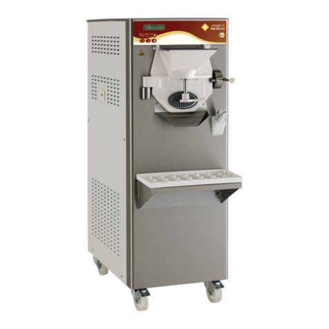
Mantematic K20S are batch freezers for the production of ice cream.
CDE H I
V Hz kW
A
Gas kg
Cod.
ANZOLA EMILIA - BOLOGNA - ITALY
Matr.
AB F G
100089654588-4
Legend:
A=Serial number
B=Machine type
C=Voltage
D=Main-switch
amperometric value
E= Gas type and weight
F= Machine code
G=Condensation
H=Frequency
I= Power input

- 10 -
Mantematic K20S
Mantematic K20S_EN - 2010/04 - Ed. 01
Cattabriga recommends to always use high quality mix for ice cream production in order to
satisfy your customers, even the hardest-to-please ones. Any saving made to the prejudice of
quality will surely turn into a loss much bigger than the saving itself.
Bearing in mind the above statements, please take heed of the following suggestions:
•Make your mixes yourselves from high quality natural ingredients or buy them from reliable
companies.
•Follow closely instructions given by your mix supplier for the preparation of the mixes.
•Do not alter your mix supplier's recipies, by adding, for instance, water or sugar.
•Taste ice cream before serving it and start selling it only if entirely satisfactory.
•Make sure your staff always keeps the machine clean.
Have your machine serviced always by companies authorized by Cattabriga.
Performances featured by a room temperature of 25°C and a cooling water temperature of 20°C.
1.2.2 Technical features
A
C
B
MODEL
Production
output Mix q.ty per
batch Electric spec. Rated
Power Condenser Dimensions cm Net
weight
kg litri Min.
lMax.
lVolt Hz Ph kW A B C kg
Mantematic
K20S 8/12 11/17 1,2 2,5 220 50 1 1,8 Air 365 715 660 96
Fig. 1

Mantematic K20S
- 11 - Mantematic K20S_EN - 2010/04- Ed. 01
1.3 INTENDED USE
The Mantematic K20S must only be used for the production of ice cream, with the respect of
what indicated in 1.2.1 "General information", within the limits indicated here under.
Voltage: ±10%
Min air temperature: 10°C
Max air temperature: 43°C
Max relative humidity: 85%
Min water temperature (*): 10°C
Max water temperature (*): 30°C
Min. water pressure (*): 0,1 MPa (1 bar)
Max water pressure (*): 0,8 MPa (8 bar)
(*) In case of water condenser.
This machine has been designed for its use in rooms not subject to explosion-proof laws; its use
is thus bound to complying rooms and normal atmosphere.
1.4 NOISE
The steady acoustic pressure level weighed A in a working place alike by watercooled and by
aircooled machines is less than 70 dB(A)
1.5 STORING A MACHINE
The machine must be stored in a dry and dump-free place.
Before storing the machine, wrap it in a cloth in order to protect it against dust and else.
1.6 DISPOSAL OF PACKING STUFFS
When opening the packing crate, separate packing stuffs per type and get rid of them according
to laws in force in machine installation country.
1.2.3 Location of machine groups
Caption:
1Four-position selector switch
2Cylinder front lid
3Shelf for drip tray
4Drip drawer
2
1
3
4
Fig. 2

- 12 -
Mantematic K20S
Mantematic K20S_EN - 2010/04 - Ed. 01
1.7 WEEE (Waste Electrical and Electronic Equipment) )
In conformity with the European Directives 2006/66/EC and 2002/96/EC, also known as WEEE,
the presence of the symbol on the side of the product or packaging means that the product must
not be disposed of with normal urban waste.
Instead, it is the user’s responsibility to dispose of this product by returning it to a collection
point designated for the recycling of electrical and electronic equipment waste.
Separate collection of this waste helps to optimize the recovery and recycling
of any reclaimable materials and also reduces the impact on human health and
the environment.
For more information concerning the correct disposal of this product, please
contact your local authority or the retailer where this product was purchased.

Mantematic K20S
- 13 - Mantematic K20S_EN - 2010/04- Ed. 01
2. INSTALLATION
2.1 ROOM NECESSARY TO THE MACHINE USE
The machine must be installed in such a way that air can freely circulate all around.
Rooms for the approach to the machine must be left free in order to enable the operator to act
without constraint and also to immediately leave working area, if need be.
The minimum approach room to working area should be at least 50 cm in consideration of space
taken by opened doors.
ATTENTION
MACHINES WITHAIRCOOLED condenser must be installed NO CLOSER THAN 50
CM TO ANY WALL IN ORDER to allow free air circulation around the condenser.
NOTE:
An insufficient air circulation affects operation and output capacity of the machine.
2.2 WATER SUPPLY CONNECTION
The machine must be connected to running water which pressure must not be higher than 0,8
MPa (8 bars).
By watercooled machines water connections (for cooling the gas) are placed on upper panel
2.3 MACHINE WITH AIRCOOLED CONDENSER
Machines with aircooled condenser must be installed no closer than 50 cm to any wall in order
to allow free air circulation around the condenser.
NOTE:
An insufficient air circulation affects operation and output capacity of the machine.
Fig. 3
50 cm
50 cm air only
20 cm20 cm

- 14 -
Mantematic K20S
Mantematic K20S_EN - 2010/04 - Ed. 01
2.4 MACHINES WITH WATERCOOLED CONDENSER
To make the machine run, a watercooled machine must be connected to running water supply,
or to a cooling tower.
Water must have a pressure of 0.1 MPa and 0.8 MPa (1-8 bar) at least, and a delivery at least
equal to the estimated hourly consumption.
Connect inlet pipe marked by plate "Water Inlet" to water supply installing a shut-off valve, and
outlet pipe marked by plate "Water Outlet" to a drain pipe, installing a shut-off valve.
2.4.1 Water valve adjustment
IMPORTANT
If water valve needs be reset, this operation will have to be carried out by skilled personnel,
only.
Valve adjustment must be carried out in such a way that no water flows when machine is off and
lukewarm water flows when machine is on.
NOTE:
Water consumption increases if temperature of entering water is above 20°C.
ATTENTION
Do not leave the machine in a room with temperature below 0°C
without first draining water from the condenser.
2.5 ELECTRIC CONNECTION
Before connecting the machine to the mains, check that machine voltage indicated in data plate
corresponds with the mains.
Insert a differential magnetothermal protection switch adequately sized to absorption capacity
required and with contact opening of 3 mm at least.
The machines are supplied complete with an electrical supply cable (five conductor leads for the
three-phase machines and three conductor leads for single-phase machines). Connect the blue
conductor lead to the neutral phase.
IMPORTANT
Yellow/green ground wire must be connected to an adeguate ground plate.
2.5.1 Replacing the power cable
Should the machine main cable be damaged, it must be replaced immediately through one with
similar features.
Replacement shall be carried out by skilled technicians, only.
IMPORTANT
Direction of rotation
Il Beater rotation is anticlockwise
Reversal of rotation (only for three-phase machines)
Should direction of rotation be wrong, reverse it by exchanging two of the three phases which
start at the differential magnetothermal protection switch.

Mantematic K20S
- 15 - Mantematic K20S_EN - 2010/04- Ed. 01
2.6 LOCATION
Stabilise the machine on the support surface to permit it to function correctly and avoid leaks of
the mixture.
2.7 REFILLING
Motor installed in the machine is of the type with lubrication for life; no action of checking/re-
placing or topping up is necessary.
Gas filling necessary to the freezing system is carried out at Cattabriga works during machine
postproduction testing.
If a gas addition happens to be made, this must be carried out by skilled technicians, only, who
can also find out trouble origin.
2.8 MACHINE TESTING
A postproduction test of the machine is carried out at CATTABRIGA premises; Operation and
output functionality of the machine are thoroughly tested.
Machine test at end user's must be carried out by skilled technicians or by one of Cattabriga
engineers.
After the machine positioning and correct connections, also carry out all operations necessary to
functional check and test of the machine.

- 16 -
Mantematic K20S
Mantematic K20S_EN - 2010/04 - Ed. 01

Mantematic K20S
- 17 - Mantematic K20S_EN - 2010/04- Ed. 01
3. DIRECTIONS FOR USE
3.1 MACHINE SAFETY WARNINGS
When using industrial equipment and plants, one must be aware of the fact that drive mechanisms
(rotarymotion),high voltagecomponents,as wellasparts subjecttohigh temperaturesmay cause
serious damages to persons and things.
Who is in charge of plant safety must be on the look-out that:
•An incorrect use or handling shall be avoided
•Safety device s must neither be removed nor tampered with
•The machine shall be regularly serviced
•Only original spare parts are to be used especially as far as those components with safety
functions are concerned (ex.: frontlid microswitch).
•That appropriate individual protection equipment is used.
To achieve the above, the following is necessary:
•At working place an instruction manual relevant to the machine should be available.
•Such documentation must be carefully read and regulations must consequently be followed.
•Only adequately skilled personnel will have to be assigned to electrical equipment.
3.2 MACHINE CONFIGURATION
The machine consists of motor drive for beater assembly drive, a cooling system with water- or
aircooled condenser.
Icecreamismadebypouringmixintothebarrelandstartingtheautomaticproductioncyclewhich
ends when right consistency of ice cream as set by Cattabrigais reached.To this purpose, minum
and maximum quantities of mix per batch must be followed, as shown in table Sec. 1.2.2. When
cycle is over, ice cream is ready for being taken out from ice cream door and poured directly in
ice cream cups and containers.
Prepare 1.2 to 2.5 litres of liquid mix, approximately 3° to 6°C, in a clean, sanitized measuring
container.
Ice cream
(end product)
Ice cream mix
Fig. 4

- 18 -
Mantematic K20S
Mantematic K20S_EN - 2010/04 - Ed. 01
3.3 CONTROLS
The machine is provided with a four-position selector switch;
Each position corresponds to a determined function of the machine described above.
STOP
Positioning the selector switch in this position stops the machine.
EXTRACTION
Positioning the selector switch in this position rotates only the beater and the
refrigeration circuit is excluded to facilitate the extraction of the ice cream.
PRODUCTION
Positioning the selector switch in this position the functioning of the beater
and compressor is completely automatic and controlled by the Hard-O-Tronic
Control.
CLEANING
Positioning the selector switch in this position rotates only the beater and the
refrigeration system is excluded.
STOP
Fig. 5
STOP
3.4 ICE CREAM UNLOADING LID
The ice cream unloading lid must be opened by the control lever 1 (Fig. 6) to extract the product
when it has reached the desired consistency.
1
Fig. 6

Mantematic K20S
- 19 - Mantematic K20S_EN - 2010/04- Ed. 01
3.5 PUTTING THE MACHINE INTO OPERATION
After installing the machine in conformity with the instructions contained in Chapter 2 “Installa-
tion” and after accurately washing and sanitising the machine as described in Chapter 5 “Disas-
sembly, cleaning and reassembly of the organs that come into contact with the product”, proceed
as follows:
Prepare a 1.5 litre to 2.5 litre quantity of mixture (3°C to 6°C temperature) in a clean and sanitised
container.
Lift the lid of the cylinder lid 1 (Fig. 7) and pour the mixture into the cylinder.
1
NOTE:
During the functioning of the machine always keep the lid 1 (Fig. 6) closed to stop dust and other
impurities from entering the mixture.
Turn the four-position selector switch to the “PRODUCTION” position and then adjust the
timer to the desired time by rotating the appropriate knob with the graduated minute scale.
Thistimeperiod variesdepending onthetemperature, typeofmixture usedand thecharacteristics
of the desired finished ice cream.
NOTE:
Indicative time for ice cream: 15 minutes.
At the end of the prefixed time on the timer, an acoustic signal advises the operator.
After a few seconds, open the ice cream unloading lid and turn the selector switch to the
“EXTRACTION” position.
Fig. 7

- 20 -
Mantematic K20S
Mantematic K20S_EN - 2010/04 - Ed. 01
Table of contents
Other Italian Gelato Ice Cream Maker manuals
Popular Ice Cream Maker manuals by other brands

Taylor
Taylor C125 Operating instructions and maintenance

SEVERIN
SEVERIN EZ 7405 Instructions for use

Ugolini
Ugolini Quick-GEL Operator's manual

Cuisinart
Cuisinart ICE-20 Series INSTRUCTION AND RECIPE BOOKLET

Aroma
Aroma AIC-305EM Instruction manual & recipe guide

Linea 2000
Linea 2000 Domo DO9207I Instruction booklet