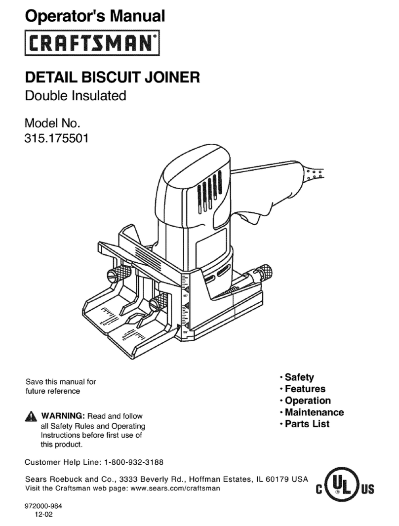
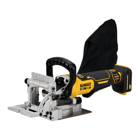
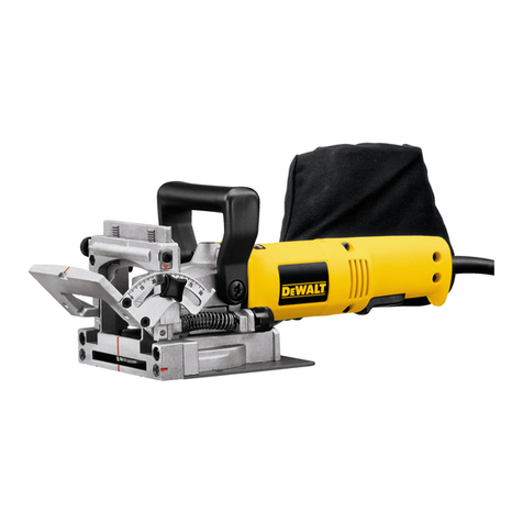
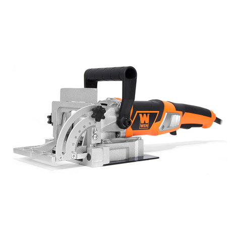
ITC SPT240 User manual

WARNING:
Read all instructions and safety warnings
before operating this equipment. Failure to
follow the instructions and safety warnings
may result in personal injury or property
damage.
CAUTIONNEMENT :
Lire les instructions et les cautionnements
avant d’utiliser cet équipement. Manquer de
suivre les instructions et les cautionnements
peut en résulter aux blessures ou aux
dommages de propriété.
!
Page 1 of 24
®
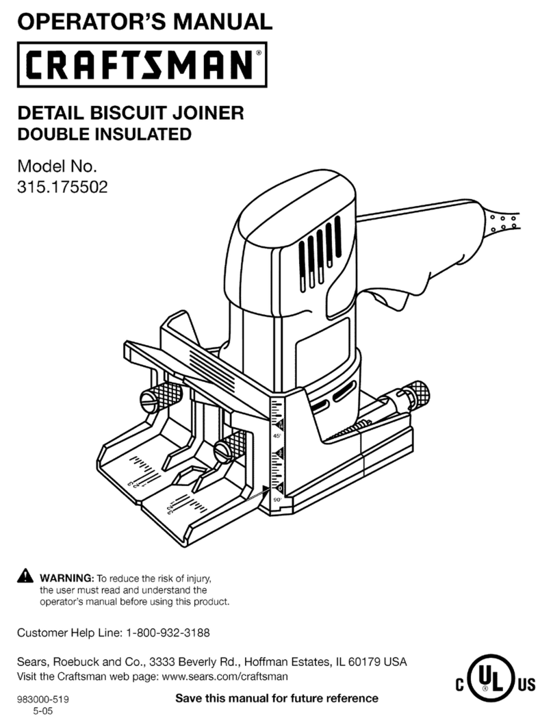
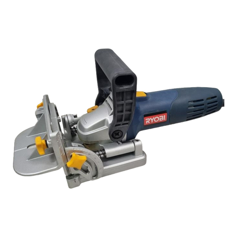
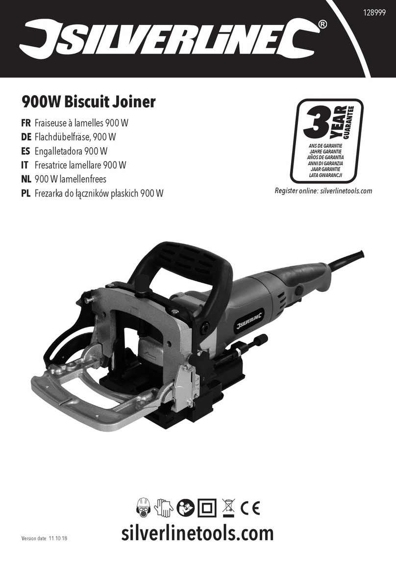
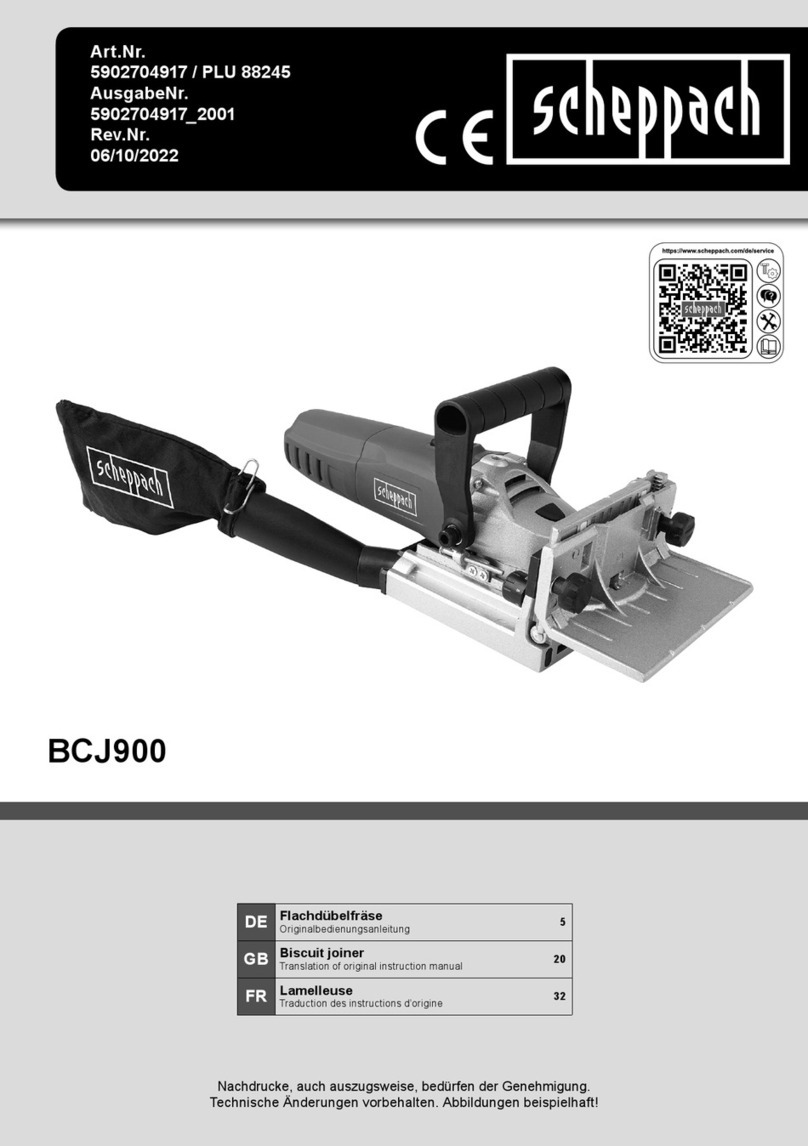
BISCUIT JOINER
Owner’s Manual
MENUISIER DE BISCUIT
Manuel du propriétaire
PROD. NO. 011951
MOD. NO. SPT240

011951 Page 2 of 24
ENGLISH
®
!
WARNING: When using electric tools, machines or equipment, basic safety
precautions should always be followed to reduce the risk of re, electric shock,
and personal injury.
READ ALL INSTRUCTIONS BEFORE USING THIS TOOL
KEEP WORK AREA CLEAN. Cluttered areas invite injuries.
CONSIDER WORK AREA ENVIRONMENT. Don’t use power tools in damp,
wet, or poorly lit locations. Don’t expose your tool to rain. Keep the work area
well lit. Don’t use tools in the presence of ammable gases or liquids.
KEEP CHILDREN AND BYSTANDERS AWAY. All children should be kept away
from the work area. Don’t let them handle machines, tools or extensions cords.
Visitors can be a distraction and are difcult to protect from injury.
GROUNDED TOOLS must be plugged into an outlet that itself is properly
installed and grounded. Grounding provided a low-resistance path to carry
electricity to ground away from the operator, should the tool malfunction
electrically. Do not remove the grounding prong from the plug or alter the plug
in any way. If in doubt as to whether the outlet is properly grounded according
to code, check with a qualied electrician.
OBSERVE PROPER PRECAUTIONS REGARDING DOUBLE INSULATION.
This tool is double insulated. It is equipped with a polarized plug. One blade is
wider than the other, so it will t into a polarized outlet only one way. If you have
difculty inserting the plug, try reversing it. If it still doesn’t t, do not alter the
plug; have a qualied electrician install a polarized outlet.
GUARD AGAINST ELECTRIC SHOCK. Prevent body contact with grounded
surfaces: pipes, radiators, ranges, and refrigerator enclosures. When your body
is grounded the risk of electric shock increases. When working wherever “live”
electrical wires may be encountered, try to ascertain whether there is a danger
of shock. Even so, DO NOT TOUCH ANY METAL PARTS OF THE TOOL while
using it. Hold the tool only by the plastic grip to prevent electric shock if you
contact a live wire.
DO NOT ABUSE THE CORD. Never carry your sander by the cord or pull
on the cord to unplug it. Protect the cord from potential sources of damage:
heat, oil & solvents, sharp edges, or moving parts. Replace damaged cords
immediately.
WHEN WORKING OUTDOORS, USE AN OUTDOOR-RATED EXTENSION
CORD. An extension cord rated for outdoor use must be marked “W-A” or “W”.
DO NOT EXPOSE ELECTRICAL POWER TOOLS TO MOISTURE. Rain or wet
conditions can cause water to enter the tool and lead to electric shock.
ENSURE THE EXTENSION CORD YOU USE IS OF SUFFICIENT GAUGE
FOR ITS LENGTH.
STORE IDLE EQUIPMENT. Store equipment in a dry area to inhibit rust.
Equipment also should be in a high location or locked up to keep out of reach of
children.
DON’T FORCE THE TOOL. It will do the job better and more safely at the rate
for which it was intended.
1.
2.
3.
4.
5.
6.
7.
8.
9.
10.
11.
12.
IMPORTANT SAFETY INSTRUCTIONS
Recommended Minimum Wire Gauge for Extension Cords
Amps from Tool Nameplate 25' length 50' length 75' length 100' length 150' length 200' length
0-5 amps 16 ga. 16 ga. 16 ga. 14 ga. 12 ga. 12 ga.
5.1-8 amps 16 ga. 16 ga. 14 ga. 12 ga. 10 ga. Do Not Use
8.1-12 amps 14 ga. 14 ga. 12 ga. 10 ga. Do Not Use Do Not Use
12.1-15 amps 12 ga. 12 ga. 10 ga. 10 ga. Do Not Use Do Not Use
15.1-20 amps 10 ga. 10 ga. 10 ga. Do Not Use Do Not Use Do Not Use
ENGLISH
Page 3 of 24 v.081119
®
USE THE RIGHT TOOL. Don’t force a small tool or attachment to do the work
of a larger industrial tool. Don’t use a tool for a purpose for which it was not
intended.
DRESS PROPERLY. Don’t wear loose clothing or jewelry; they can be caught
in moving parts. Protective, non-electrically conductive gloves and non-skid
footwear are recommended when working. Wear protective hair covering to
contain long hair and keep it from harm.
USE EYE PROTECTION. Use a full-face mask if the work you’re doing
produces metal lings, dust or wood chips. Goggles are acceptable in other
situations. Wear a clean dust mask if the work involves creating a lot of ne or
coarse dust.
SECURE WORK. Use clamps or a vise to hold the work. It’s safer than using
your hands and it frees both hands to operate the tool.
DON’T OVERREACH. Keep proper footing and balance at all times. Do not
reach over or across machines that are running.
MAINTAIN TOOLS WITH CARE. Keep tools sharp and clean for better and
safer performance. Follow instructions for lubricating and safe performance.
Follow instructions for lubricating and changing accessories. Keep handles dry,
clean and free from oil and grease.
AVOID UNINTENTIONAL STARTING. Be sure the switch is in the OFF position
before plugging in.
ALWAYS CHECK AND MAKE SURE TO REMOVE ANY ADJUSTING KEYS
OR WRENCHES before turning the tool on. Left attached, these parts can y
off a rotating part and result in personal injury.
DO NOT USE THE TOOL IF IT CANNOT BE SWITCHED ON OR OFF. Have
your tool repaired before using it.
DISCONNNECT THE PLUG FROM POWER BEFORE MAKING ANY
ADJUSTMENTS. Changing attachments or accessories can be dangerous if
the tool could accidentally start.
STAY ALERT. Watch what you are doing & use common sense. Don’t operate
any tool when you are tired.
CHECK FOR DAMAGED PARTS. Before using this tool, any part that is
damaged should be carefully checked to determine that it will operate properly
and perform its intended function. Check for alignment of moving parts, binding
of moving parts, breakage of parts, mountings, and other conditions that may
affect its operation. Inspect screws and tighten any ones that are loose. Any
part that is damaged should be properly repaired or replaced by an authorized
service center unless otherwise indicated elsewhere in the instruction manual.
Have defective switches replaced by an authorized service center. Don’t use
the tool if switch does not turn it on and off properly.
REPLACEMENT PARTS. When servicing, use only identical replacement parts.
SERVICE AND REPAIRS should be made by qualied repair technicians at an
authorized repair centre. Improperly repaired tools could cause serious shock
or injury.
13.
14.
15.
16.
17.
18.
19.
20.
21.
22.
23.
24.
25.
26.
IMPORTANT SAFETY INSTRUCTIONS
ELECTRICAL SAFETY
Always check that the power supply corresponds to the voltage on the rating
plate.
Your machine is double insulated. Therefore, no earth wire is required.
Replacing cables or plugs: Immediately throw away old cables or plugs when
they have been replaced by new ones. It is dangerous to insert the plug of a
loose cable in the wall socket.
Using extension cords: Only use an approved extension cable suitable for the
power input of the machine. When using a cable reel always unwind the reel
completely.

011951 Page 4 of 24
ENGLISH
®
Voltage 110 V
Power 900 W
No-load speed 11,000 rpm
Cutter diameter 100 mm (4")
Cutter bore 20 or 22 mm (3/4 or 7/8")
Maximum cut depth 18 mm (11/16")
Fence adjustment 0 - 90 degrees
Dimension d’axe M10
Poids 3.0 kg (6.7 lb.)
Sound pressure Lpa 89.6 dB(A)
Lwa (sound power) 102.6 dB(A)
Vibration 1.9 m/s3
PRODUCT INFORMATION
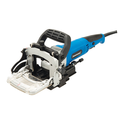
The Biscuit Joiner is suitable for cutting grooves for
biscuit joints in solid wood, plywood, chipboard, bre
board, Plexiglas, and articial marble.
1. On/Off Switch
2. Auxiliary handle
3. Spindle lock
4. Angle Stop
5. Scale for the fence angle
6. Cutting depth for adjustment knob
7. Clamping lever for angle adjustment
8. Clamping lever for height adjustment
9. Knob for height adjustment
10. Scale for height adjustment
11. Base plate
12. Dust bag collection
13. Dust bag
14. Motor base
CONTENTS
The carton contains:
1 biscuit joiner
1 cutter blade
1 wrench
1 dust bag
1 instruction manual
Examine the tool, loose pieces, and accessories to determine if there has been any
damage due to transport
SPECIFICATIONS

ENGLISH
Page 5 of 24 v.081119
®
ADJUSTING THE MACHINE
ADJUSTING THE CUTTING DEPTH
Move the motor base (15, g.B) as far as possible backwards
Set the cutting depth by turning the cutting depth adjustment knob (7, g.B)
Move the motor base forward and check if the pin (A, Fig.B) will fall in the notch
of the adjustment knob.
The following table shows the relationship of the markings on the adjustment knob
to cutting depth, the thickness of material and associated biscuit dowels.
1.
2.
3.
Marking Thickness Of Material Biscuit Size Cutting Depth
0 8 - 12 mm No. 0 8 mm
10 12 - 15 mm No. 10 10 mm
20 > 15 mm No. 20 12.3 mm
S - Simplex 13 mm
D-Duplex 14.7 mm
Max. - - 18 mm
ADJUSTING THE CUTTING ANGLE
The cutting angle can be set by unlocking the clamping lever (8, g.C) and put
the fence stop (4, g. C) in the required angle.
Should the clamping lever be in the way when working with the tool, then pull
the clamping lever out and fasten it in a different position without changing the
cutting angle.
ADJUSTING THE HEIGHT
The correct height can be set by unlocking the clamping lever (9, g.D) and
turning the knob for the height adjustment (10, g.D) to the desired height with
aid of the scale (11, g.D).
The height must correspond to half of the material thickness of the working
piece, the groove for the biscuit dowel must always be in the middle of the
working piece.
Should the clamping lever be in the way when working with the tool, then pull
the clamping lever out and fasten it in a different position without changing the
height.

011951 Page 6 of 24
ENGLISH
®
!
!
MOUNTING ACCESSORIES
WARNING: Disconnect the plug from the main socket
MOUNTING THE SAWBLADE
Loosen the Allen screw (16, g.E) with the supplied Allen wrench and open the
top of the base plate.
Press the spindle lock and turn the spindle (17, g.E) until it engages in the
lock. Keep the spindle lock pressed during this procedure.
Remove the ange nut (18, g.E) from the spindle using the wrench (19, g.E)
Position the sawblade (20, g.E) on the ange. (21, g.E)
Place the ange nut (18) from the spindle (17) and tighten it with the wrench
(19).
The ange nut has two sides. One for sawblades with bore 20 mm and the
other side for sawblades with bore 22 mm.
Pay close attention that the ange nut will be placed with the correct side on the
spindle.
Release the spindle lock and check that the spindle is unlocked by rotating it.
Close the top of the base plate and fasten the Allen screw (16) with the supplied
Allen wrench.
WARNING: Make sure that the top of the base plate is securely closed before
operating the machine.
ALWAYS CHECK THE CUTTING DEPTH AFTER MOUNTING A SAW BLADE.
Disconnect the plug from the socket.
Move the motor base (15, g.F) as far as possible backwards.
Set the cutting depth in the maximum position by turning the depth adjustment
knob. (7, g.F)
Move the motor base forwards until the pin (A, g.F) falls into the notch in the
adjustment knob (7).
Turn the saw blade until one tooth of the saw blade is in the front position.
Measure the distance from the side of the base plate to the tooth of the saw
blade.
Check if the distance is 18 mm. The maximum position is 18 mm.
SETTING THE CUTTING DEPTH
When cutting depth is not correct, it can be adjusted as follows:
Move the motor base (15) as far as possible backwards.
Loosen the pin (A)
Set the cutting depth by turning the screw. The screw is positioned at the back
of pin (A).
Repeat the procedure until the cutting depth is correct.
Fasten the pin (A).
1.
2.
3.
4.
5.
6.
7.
8.
9.
1.
2.
3.
4.
5.
6.
7.
1.
2.
3.
4.
5.

ENGLISH
Page 7 of 24 v.081119
®
!
SWITCHING ON AND OFF
To switch the machine on, slide the on/off switch forward.
The switch will automatically move to the “off” position.
WARNING: Never use the spindle lock to stop the motor.
MARKING THE WORKPIECES
Before starting with the Biscuit Joiner, the workpieces must be marked as shown
(g.G):
Place the two workpieces which are to be connected on top of each other.
Clamp the workpieces and mark the center of the groove.
The space between two grooves should be 10 – 15 cm. There is no concern for
smaller workpieces. Smaller workpieces don’t have to be marked.
1.
2.
3.
POSITIONING THE MACHINE
Based on the size of the workpieces, the machine can be positioned in several
ways.
LARGE WORKPIECES
Place the machine near the workpiece.
The middle of the base plate (this point is marked on the base plate) must be
facing the center of the groove in the workpiece (see marking the workpieces).
SMALL WORKPIECES
Place the machine near the workpiece.
The side of the machine must be even with the side of the workpiece (g. I).
OPERATING PROCEDURES

011951 Page 8 of 24
ENGLISH
®
!
CUTTING GROOVES
Move the motor base backwards.
Place the machine against the workpiece.
Position the machine (see positioning the machine)
Hold the machine with both hands and switch the machine on.
Push the motor base carefully forward as far as possible.
Move the motor base backwards and switch the machine off.
JOINING WORKPIECES
When the grooves in both workpieces have been made, the workpieces can be
joined together.
Put glue in both grooves.
Place the biscuit in the groove of one workpieces.
Fit the other workpiece onto the biscuit.
Clamp the workpieces and wait until the glue is dry.
1.
2.
3.
4.
5.
6.
1.
2.
3.
4.
MAINTENANCE
WARNING: Make sure that the machine is not live and that it is unplugged when
carrying out maintenance work on the motor.
This tool has been designed to operate over as long period with a minimum of
maintenance. Continuous satisfactory operation depends upon proper machine
care and regular cleaning.
CLEANING
Regularly clean the machine housing with a soft cloth, preferably after each use.
Keep the ventilation slots free from dust and dirt.
If the dirt does not come off, use a soft cloth moistened with soapy water. Never
use solvents such as petrol, alcohol, and ammonia water, etc. These solvents
may damage the plastic parts.
OPERATING PROCEDURES
THIN WORKPIECES
(thinner than 16 mm)
Place the machine near the workpiece
Place the adjustment plate (5, g.J) against the angle stop (4, g.J).
Take care setting the height. The groove for the biscuit MUST be in the middle of
the workpiece.
NOTE: On workpieces thinner than 16 mm, it is not possible to make the groove
for the biscuit in the middle of the workpiece without the aid of the adjustment
plate.

ENGLISH
Page 9 of 24 v.081119
®
ITC branded power tools, air nailers staplers and compressors are designed for
use in DIY (do-it-yourself), light or intermittent duty, semi-professional applications.
They are not intended for use in professional, production, industrial or continual use
applications.
ITC makes every effort to ensure that its products meet high quality and durability
standards and are warranted for two years against manufacturers’ faults and
defects for a period of two years from the date of purchase to the original owner.
ITC will REPAIR OR REPLACE (at our discretion) merchandise deemed by the
company to be defective, provided that it is has not been misused, abused, altered,
or repaired by anyone other than an authorized repair centre.
Please consult the ITC catalogue or your nearest ITC distributor to determine those
products that are covered by our over-the counter warranty. Any ITC tool that fails
during normal use and within the specied warranty period and qualies for over-the
counter warranty must be returned to its point of purchase for replacement or credit.
Any item not listed as over-the-counter warranty must be shipped, prepaid freight,
to an authorized repair depot accompanied by a copy of the invoice specifying the
date that the item was purchased. Returned tools that are not accompanied by a
proof of purchase (Copy of Invoice) will not be repaired or replaced under warranty.
This warranty does not extend to normal wear or consumable parts such as brad
and staple gun driver blades, grinding discs, saw blades, driver bits, electric motor
brushes, worn chords, etc. It also does not apply to ITC tools used in professional,
production, industrial or continual use applications.
For a listing of the authorized repair centers please refer to the ITC catalogue.
Keep the moving parts of the machine clean, like the guiding pillars, the
mechanism of the height adjustment and angle adjustment, to ensure good
working order.
LUBRICATION
This machine does not require any lubrication or lubricants.
MAINTENANCE
WARRANTY

011951 Page 10 of 24
ENGLISH
®
NOTES

ENGLISH
Page 11 of 24 v.081119
®
PARTS LIST
PART NO. DESCRIPTION QTY.
1Protecting Cover 1
2 Rubber Seal 1
3 Flange 1
4Blade 1
5Flange 1
6 Base 1
7 Dust Tube 1
8Dust Port 1
9O-ring 1
10 Fixed Screw 1
11 Bowling Washer 1
12 Location Screw 1
13 Distance System 1
14 Spring 2
15 Small Spring 2
16 Steel Ball 2
17 Nut 1
18 Washer 2
19 Locking Knob 2
20 Nut M6 2
21 Flat Washer 2
22 Pin 2
23 Washer 2
24 Fence 1
25 Bolt M6 x 20 1
26 Washer 2
27 Plastic Gear 1
28 Angled Guide Plate 1
29 Knob 1
30 Spring 1
31 Balance Plate 1
32 Bolt M6 x 20 1
33 Guiding Pillar 2
34 Screw M4 x 30 4
35 Spring Washer 4
36 Flat Washer 11
37 Front Cover 1
38 Spindle 1
PART NO. DESCRIPTION QTY.
39 Key 2
40 Bearing 6000ZZ 1
41 Spring Washer 1
42 Location Cover 1
43 Large Gear 1
44 Spring Washer 1
45 Bushing 1
46 Variable Speed System 1
47 Screw M8 x 16 2
48 Flat Washer 4
49 Handle 1
50 Self Locking Pin 1
51 Pin Spring 1
52 Screw ST3 x 25 4
53 Small Gear 1
54 Bearing 629ZZ 1
55 Exhaust Vent 1
56 Bearing Plate 629 1
57 Washer 2
58 Screw M4 x 12 2
59 Rotor 1
60 Fan Guide 1
61 Bearing 627ZZ 1
62 Bearing Housing 1
63 Capacitor 1
64 Nut M5 1
65 Screw M5 x 35 2
66 Screw ST3.9 x 65 1
67 Stator 1
68 Switch Button 1
69 Housing 1
70 Slide Bar 1
71 Switch Spring 1
72 Brush Holder 2
73 Brush 2
74 Brush Holder Cover 2
75 Cable Clip 1
76 Screw ST3.9 x 13 6
Please refer to Schematic Drawing on pages following

ENGLISH
FRANÇAIS
011951 Page 12 of 24
SCHEMATIC DRAWING / SCHéMA
PART NO. DESCRIPTION QTY.
77 Switch 1
78 Inductor 2
79 Switch Clip 1
80 Cable Protector 1
81 Rating Plate 1
82 Rear Cover 1
83 Screw ST3.9 x 16 1
84 Cable 1
85 Dust Bag 1
86 Wrench 1

FRANÇAIS
ENGLISH
®
Page 13 of 24 v.081119
NO. de PIÈCE DESCRIPTION QTÉ.
1 Couvercle protecteur 1
2Joint étanche en caoutchouc 1
3Collet 1
4 Lame 1
5 Collet 1
6 Base 1
7 Tube à sciure 1
8 Orice à sciure 1
9Joint torique 1
10 Vis xe 1

ENGLISH
FRANÇAIS
011951 Page 14 of 24
NO. de PIÈCE DESCRIPTION QTÉ.
11 Rondelle 1
12 Vis d’alignement 1
13 Système d’espacement 1
14 Ressort 2
15 Petit ressort 2
16 Bille d’acier 2
17 Écrou 1
18 Rondelle 2
19 Bouton de blocage 2
20 Écrou M6 2
21 Rondelle plate 2
22 Cheville 2
23 Rondelle 2
24 Guide 1
25 Boulon M6 x 20 1
26 Rondelle 2
27 Plastic Gear 1
28 Angled Guide Plate 1
29 Knob 1
30 Ressort 1
31 Plaque d’équibrillage 1
32 Boulon M6 x 20 1
33 Pilier de guidage 2
34 Vis M4 x 30 4
35 Rondelle à ressort 4
36 Rondelle plate 11
37 Couvercle avant 1
38 Fuseau 1
39 Clé 2
40 Roulement à billes 6000ZZ 1
41 Rondelle à ressort 1
42 Couvercle d’alignement 1
43 Gros engrenage 1
44 Rondelle à ressort 1
45 Douille 1
46 Système à vitesse variable 1
47 Vis M8 x 16 2
48 Rondelle plate 4
NO. de PIÈCE DESCRIPTION QTÉ.
49 Poignée 1
50 Cheville à blocage automatique 1
51 Ressort de cheville 1
52 Vis ST3 x 25 4
53 Petit engrenage 1
54 Roulement à billes 629ZZ 1
55 Bouche de ventilation externe 1
56 Plaque de coussinet 629 1
57 Rondelle 2
58 Vis M4 x 12 2
59 Rotor 1
60 Guide de ventilateur 1
61 Roulement à billes 627ZZ 1
62 Boîtier de roulement à billes 1
63 Condensateur 1
64 Écrou M5 1
65 Vis M5 x 35 2
66 Vis ST3.9 x 65 1
67 Inducteur 1
68 Bouton de commutateur 1
69 Boîtier 1
70 Pôle de commutateur 1
71 Ressort de commutateur 1
72 Porte-balai 2
73 Balai 2
74 Couvercle de porte-balai 2
75 Agrafe de cable 1
76 Vis ST3.9 x 13 6
77 Commutateur 1
78 Inductance 2
79 Agrafe de commutateur 1
80 Protecteur de cable 1
81 Plaque de spécications 1
82 Couvercle arrière 1
83 Vis ST3.9 x 16 1
84 Câble 1
85 Sac à sciure 1
86 Clé anglaise 1
LISTE DES PIÈCES
Veuillez consulter le schéma aux pages précédantes.

FRANÇAIS
®
Page 15 of 24 v.081119
!
AVERTISSEMENT : Durant l’usage des outils électriques, des machines et
de l’équipement, des précautions de sécurité de base devraient toujours être
observées pour réduire le risque d’incendie, de choc électrique et de blessures
corporelles.
LIRE TOUTES LES INSTRUCTIONS AVANT
D’UTILISER CET OUTIL.
CONSERVEZ L’AIRE DE TRAVAIL PROPRE. Le désordre invite les blessures.
SOYEZ CONSCIENT DE VOTRE ENVIRONNEMENT DE TRAVAIL. Ne
pas utiliser les outils motorisés dans des endroits humides, mouillés ou
insufsamment éclairés. Ne pas exposer vos outils à la pluie. Conservez l’aire
de travail bien éclairée. Ne pas utiliser les outils en présence de gaz ou de
liquides inammables.
CONSERVEZ LES ENFANTS ET LES SPECTATEURS À L’ÉCART. Tous les
enfants doivent être tenus à l’écart de l’aire de travail. Ne leur permettez pas de
toucher les machines, les outils ou les cordes de rallonge. Les visiteurs peuvent
causer une distraction et on doit les protéger contre les blessures corporelles.
LES OUTILS MIS À LA TERRE doivent être branchés dans une prise qui
elle-même a été installée et mise à la terre adéquatement. Si l’outil avait
un problème électrique, la mise à la terre offre un cheminement de faible
résistance transportant l’électricité à la mise à la terre loin de l’opérateur. Ne
jamais enlever la broche de mise à la terre ou modier la che. En cas de
doute quant à l’installation appropriée de la mise à la terre, consultez avec un
électricien qualié.
PRENEZ LES PRÉCAUTIONS APPROPRIÉES CONCERNANT L’ISOLATION
DOUBLE. Cet outil est doublement isolé. Il est équipé d’une che polarisée.
Une lamelle de la che est plus large que l’autre et elle ne s’adaptera à une
prise de courant polarisée que d’une seule façon. Si vous éprouvez des
difcultés pour insérer la che, inversez-la. Si elle ne s’adapte toujours pas, ne
pas tenter de modier la che. Demandez à un électricien qualié d’installer
une prise de courant polarisée.
PRÉVENEZ LES CHOCS ÉLECTRIQUES. Éviter le contact de votre
corps avec les surfaces mises à terre : tuyaux, radiateurs, cuisinières et
réfrigérateurs. Si votre corps est mis à la terre, le risque de choc électrique
est augmenté. Si vous effectuez des travaux dans les secteurs où des ls
électriques sous tension pourraient être touchés, tentez de déterminer s’il y a
un risque de choc électrique. Mais en toute circonstance, NE PAS TOUCHER
AUNE PARTIE MÉTALLIQUE DE L’OUTIL durant son usage. Toujours tenir
l’outil par la poignée en plastique pour prévenir les chocs électriques en cas de
contact avec un l sous tension.
NE PAS ABUSER LE CORDON. Ne jamais transporter votre ponceuse par
le cordon ou tirer sur le cordon pour le débrancher. Protégez le cordon des
sources potentielles de dommage : La chaleur, l’huile et les solvants, les
rebords aiguisés ou les pièces mobiles. Remplacez les cordons endommagés
immédiatement.
POUR LE TRAVAIL À L’EXTÉRIEUR, TOUJOURS UTILISER UNE CORDE
DE RALLONGE HOMOLOGUÉE POUR L’USAGE À L’EXTÉRIEUR. Une
corde de rallonge homologuée pour usage à l’extérieur doit porter la marque
« W-A » ou « W ».
NE PAS EXPOSER LES OUTILS ÉLECTRIQUES À L’HUMIDITÉ. La pluie ou
les conditions humides peuvent causer l’inltration d’eau dans l’outil et il peut
1.
2.
3.
4.
5.
6.
7.
8.
9.
IMPORTANTE DIRECTIVES DE SéCURITé

FRANÇAIS
®
011951 Page 16 of 24
IMPORTANTE DIRECTIVES DE SéCURITé
ASSUREZ-VOUS QUE LA CORDE DE RALLONGE QUE VOUS UTILISEZ
EST DE CALIBRE SUFFISANT POUR SA LONGUEUR.
REMISEZ L’ÉQUIPEMENT QUI N’EST PAS UTILISÉ. Remisez l’équipement
dans un endroit sec pour empêcher la rouille. L’équipement devrait aussi
être remisé dans un endroit haut ou sous clé, hors d’atteinte de la portée des
enfants.
NE PAS FORCER L’OUTIL. Il fera un meilleur travail, de manière plus
sécuritaire, au rythme pour lequel il est conçu.
UTILISEZ L’OUTIL APPROPRIÉ. Ne pas forcer un petit outil ou un accessoire
à faire le travail d’un outil industriel plus gros. Ne pas utiliser un outil à une n
pour laquelle il n’a pas été conçu.
HABILLEZ-VOUS DE MANIÈRE APPROPRIÉE. Ne pas porter de vêtement
ample ou de bijoux. Ils peuvent être attrapés par les pièces mobiles.
Des gants de protection à l’épreuve de la conductivité électrique et des
souliersantidérapants sont recommandés durant le travail. Portez un
couvre-tête de protection pour recouvrir les cheveux longs et prévenir les
emmêlements.
PROTÉGEZ VOS YEUX. Utilisez un masque qui recouvre le visage tout entier
si le travail que vous effectuez produit de la limaille métallique, de la poussière
ou des éclats de bois. Des lunettes de sécurité sont appropriées dans les
autres situations. Portez un masque à poussière propre si le travail implique la
création d’une quantité appréciable de poussière ne ou à gros grains.
FIXEZ SOLIDEMENT LA PIÈCE DE TRAVAIL. Utilisez des pinces ou un étau
pour tenir la pièce de travail. C’est beaucoup plus sécuritaire que l’usage de
vos mains et ceci libère vos deux mains pour contrôler l’outil.
NE PAS VOUS ÉTIREZ. Conservez vos pieds sur le sol et maintenez votre
équilibre en tout temps. Ne vous avancez pas au-dessus ou à travers les
machines qui sont en mode de fonctionnement.
MAINTENEZ L’OUTIL EN BON ÉTAT. Conservez l’outil eflé et propre pour
une meilleure performance et plus de sécurité. Observez les instructions
pour la lubrication et la performance sécuritaire. Respectez les directives
de lubrication et de changement des accessoires. Conservez les poignées
propres, sèches et libres d’huile et de graisse.
ÉVITEZ LA MISE EN MARCHE ACCIDENTELLE. Assurez-vous que
l’interrupteur est à la position « ARRÊT » avant de brancher l’outil.
TOUJOURS VÉRIFIEZ ET RETIREZ LES CLÉS DE RÉGLAGE ET LES CLÉS
ANGLAISES avant de mettre l’outil en marche. Laissez en place, ces pièces
peuvent se détacher de la pièce qui tourne et causer des blessures.
21. NE PAS UTILISER L’OUTIL SI L’INTERRUPTEUR « EN MARCHE /
ARRÊT » NE FONCTIONNE PAS CORRECTEMENT. Faire réparer votre outil
avant de l’utiliser.
DÉBRANCHEZ L’OUTIL DE LA PRISE DE COURANT AVANT DE FAIRE
LES RÉGLAGES. Les changements de pièce ou d’accessoire peuvent être
dangereux si l’outil peut être activé accidentellement.
10.
11.
12.
13.
14.
15.
16.
17.
18.
19.
20.
21.
22.
Calibre minimum recommandé pour les cordons de rallonge
Indice d’intensité (ampère) Longueur de Longueur de Longueur de Longueur de Longueur de Longueur de
7,6 m(25 pi.) 15,2 m(50 pi.) 22,9 m(75 pi.) 30,4 m(100 pi.) 45,7 m(150 pi.) 60,9 m(200 pi.)
0-5 amp. cal. 16 cal. 16 cal. 16 cal. 14 cal. 12 cal. 12
5.1-8 amp. cal. 16 cal. 16 cal. 14 cal. 12 cal. 10 Ne pas utiliser
8.1-12 amp. cal. 14 cal. 14 cal. 12 cal. 10 Ne pas utiliser Ne pas utiliser
12.1-15 amp. cal. 12 cal. 12 cal. 10 cal. 10 Ne pas utiliser Ne pas utiliser
15.1-20 amp. cal. 10 cal. 10 cal. 10 Ne pas utiliser Ne pas utiliser Ne pas utiliser

FRANÇAIS
®
Page 17 of 24 v.081119
SOYEZ ALERTE. Surveillez vos mouvements et utilisez le sens commun.
N’utilisez pas un outil quand vous êtes fatigué.
EXAMINEZ POUR DES PIÈCES ENDOMMAGÉES. Avant d’utiliser cet outil,
toute pièce qui est endommagée devrait être soigneusement examinée pour
s’assurer qu’elle fonctionnera adéquatement et qu’elle remplira sa fonction.
Vériez pour l’alignement et le coincement des pièces mobiles, le bris des
pièces, les montures et toutes autres conditions qui pourraient affecter dans
lesonfonctionnement. Examinez les vis et resserrez celles qui sont relâchées.
Toute pièce qui est endommagée devrait être correctement réparée ou
remplacée par le centre de service autorisé, sauf si autrement indiqué ailleurs
manuel de l’utilisateur. Les interrupteurs défectueux doivent être remplacés
par un centre de service autorisé. Ne pas utiliser l’outil si l’interrupteur ne
fonctionne pas correctement.
PIÈCES DE RECHANGE. Pour le service, n’utilisez que des pièces de
rechange identiques seulement.
SERVICE ET RÉPARATION doivent être effectués par des techniciens
qualiés à un centre de service autorisé. Des outils qui ne sont pas réparés
adéquatement peuvent causés un choc ou des blessures graves.
23.
24.
25.
26.
IMPORTANTE DIRECTIVES DE SéCURITé
SÛRETé éLECTRIQUE
Vériez toujours que l’alimentation d’énergie correspond à la tension de la
plaque de contrôle.
Votre machine est double isolée. Par conséquent, aucun l de la terre n’est
exigé.
Remplacement des câbles ou des prises : Jetez immédiatement les vieux
câbles ou prises quand ils ont été remplacés par des neufs. Il est dangereux
d’insérer la prise de câble lâche dans la prise murale.
Employer des cordes de prolongation : Employez seulement un câble
approuvé de prolongation approprié pour la puissance fournie de la machine.
La taille minimum de câble est 1.5mm carré. En utilisant une bobine de câble
déroulez toujours la bobine complètement.
Ce paquet contient :
1 menuisier de biscuit
1 lame de scie
1 clé
1 sac de dépoussiérage
1 manuel d’instruction
Examinez la machine, les pièces lâches et les accessoires pour déceler les
dommages de transport.
TABLE DES MATIÈRES DE PAQUET

FRANÇAIS
®
011951 Page 18 of 24
AJUSTEMENT DE LA MACHINE
AJUSTEMENT DE LA PROFONDEUR DE DÉCOUPAGE
Déplacez la base de moteur aussi loin que possible vers l’arrière (15, g.B)
Placez la profondeur de découpage en tournant le bouton d’ajustement de
profondeur de découpage (7, g.B).
Faites avancer la base de moteur et vériez si la goupille (A, g.B) tombera
dans l’entaille du bouton d’ajustement
1.
2.
3.
SPéCIFICATIONS
Le jointer de biscuit convient aux cannelures de découpage
pourdes joints de doigt de biscuit en bois plein, contre-
plaqué,chipboard, panneau de particules, Plexiglass et marbre
articie.
1. Commutateur “Marche/Arrêt”
2. Poignée auxiliaire
3. Serrure d’axe
4. Arrêt d’Angle
5. Balance pour l’angle de barrière
6. Profondeur de découpage pour le bouton d’ajustement
7. Retenue du levier pour l’ajustement d’angle
8. Retenue du levier pour l’ajustement de taille
9. Bouton pour l’ajustement de taille
10. Balance pour l’ajustement de taille
11. Embase
12. Collection de sac de poussière
13. Sac de poussière
L’INFORMATION DE PRODUIT
Tension 110 V
Puissance fournie 900 W
Vitesse sans charge 11 000 tr/min
Diamètre de disque 100 mm (4 po)
Diamètre d’alésage de lame 20 ou 22 mm (3/4 ou 7/8 po)
Profondeur maximum de découpage 18 mm – 11/16 po
Ajustement de Barrière 0 - 90 degrés
Dimension d’axe M10
Poids 3,0 kg (6,7 lb.)
Lpa (pression acoustique) 89,6 dB(A)
Lwa (niveau de puissance sain) 102,6 dB(A)
Valeur de vibration 1,9 m/s carré

FRANÇAIS
®
Page 19 of 24 v.081119
!
AJUSTEMENT DE L’ANGLE DE DÉCOUPAGE
L’angle de découpage peut être placé en ouvrant le levier de retenue (8, g.C) et
mettre l’arrêt d’angle (4, g.C) dans l’angle exigé.
Si le levier de retenue est de la manière en travaillant avec l’outil, alors tire le
levier de retenue et l’attache en position différente sans changer l’angle de
découpage.
AJUSTEMENT DE LA TAILLE
La taille correcte peut être placée en ouvrant le levier de retenue (9, g.D) et en
tournant le bouton pour l’ajustement de taille (10, g.D) à la taille désirée à l’aide
de la balance (11, g.D).
La taille doit correspondre à la moitié de l’épaisseur matérielle du morceau
fonctionnant, la cannelure pour le doigt de biscuit doit toujours être au milieu du
morceau fonctionnant.
Si le levier de retenue est de la manière en travaillant avec l’outil, alors tire le
levier de retenue et l’attache en position différente sans changer la taille.
AJUSTEMENT DE LA MACHINE
Inscription Épaisseur de matériel Doigt de
biscuit Profondeur de découpage
0 8 à 12 mm No. 0 8 mm
10 12 à 15 mm No. 10 10 mm
20 > 15 mm No. 20 12,3 mm
S - Simplex 13 mm
D-Duplex 14,7 mm
Max. - - 18 mm
AVERTISSEMENT : Démontez la prise de la douille principale
ATTACHER LA LAME
Desserrez le boulon à tête creuse (16, g.E) avec la clé mâle fournie et ouvrez
le dessus de l’embase.
Serrez la serrure d’axe et tournez l’axe (17, g.E) jusqu’à ce qu’il s’engage dans
la serrure. Maintenez la serrure d’axe serrée pendant ce procédé.
Enlevez l’écrou de bride (18, g.E) de l’axe à l’aide de la clé (19, g.E)
Placez la lame de scie (20, g.E) sur la bride. (21, g.E)
Placez l’écrou de bride (18) de l’axe (17) et serrez-l’avec la clé. (19)
1.
2.
3.
4.
5.
ACCESSOIRES DE SUPPORT

FRANÇAIS
®
011951 Page 20 of 24
!
!
ACCESSOIRES DE SUPPORT
CHANGEMENT EN MARCHE ET EN ARRÊT
Pour commuter la machine glissez à l’avant le commutateur “Marche/Arrêt”.
Le commutateur se déplacera automatiquement à la position de “off”.
AVERTISSEMENT : N’utilisez jamais la serrure d’axe pour arrêter le moteur.
MARQUER L’OBJET
Avant commençant par le jointer de biscuit, les objets doivent être marqués comme
suit (g.G) :
Placez les deux objets, qui doivent être reliés, sur l’un l’autre.
1.
l’écrou de bride a deux côtés. Un pour des lames de scie avec l’alésage 20
millimètres et l’autre côté pour des lames de scie avec l’alésage 22mm.
Une attention particulière de salaire que l’écrou de bride sera placé avec le côté
correct sur l’axe.
Libérez la serrure d’axe et vériez que l’axe est ouvert en la tournant.
Étroit le dessus de l’embase et attachent le boulon à tête creuse (16) avec la
clé mâle Fournie.
AVERTISSEMENT : Assurez-vous que le dessus de l’embase est solidement
fermé avant d’actionner la machine.
VÉRIFIEZ TOUJOURS LA PROFONDEUR DE DÉCOUPAGE APRÈS MONTAGE
D’UNE LAME DE SCIE.
Démontez la prise de la douille.
Déplacez la base de moteur (15, g.F) aussi loin que possible vers l’arrière.
Placez la profondeur de découpage en position maximum en tournant le bouton
d’ajustement de profondeur. (7, g.F).
Déplacez la base de moteur en avant jusqu’à la goupille (A, g.F) tombera dans
l’entaille du bouton d’ajustement (7).
Tournez la lame de scie jusqu’à ce qu’une dent de la lame de scie soit en
position avant.
Mesurez la distance du côté de l’embase à la dent de la lame de scie.
Vériez si la distance est 18 mm. La position maximum est 18 mm.
RÉGLAGE DE LA PROFONDEUR DE DÉCOUPAGE
Quand la profondeur de coupure n’est pas correcte, elle peut être ajustée comme
suit:Déplacez la base de moteur (15) aussi loin que possible vers l’arrière.
Détachez la goupille (A)
Placez la profondeur de découpage en tournant la vis. La vis est placée au fond
de la goupille (A).
Répétez le procédé jusqu’à ce que la profondeur de découpage soit correcte.
Attachez la goupille (A).
6.
7.
8.
9.
1.
2.
3.
4.
5.
6.
7.
1.
2.
3.
4.
5.
OPéRATION
Table of contents
Languages: