manuals.online logo
Brands
  1. Home
  2. •
  3. Brands
  4. •
  5. ITOH DENKI
  6. •
  7. DC Drive
  8. •
  9. ITOH DENKI Power Moller 24 Series User manual

ITOH DENKI Power Moller 24 Series User manual

1
Document non contractuel. Nous nous réservons le droit à tout moment de lui apporter toutes modications que nous jugerons utiles. © ITOH DENKI
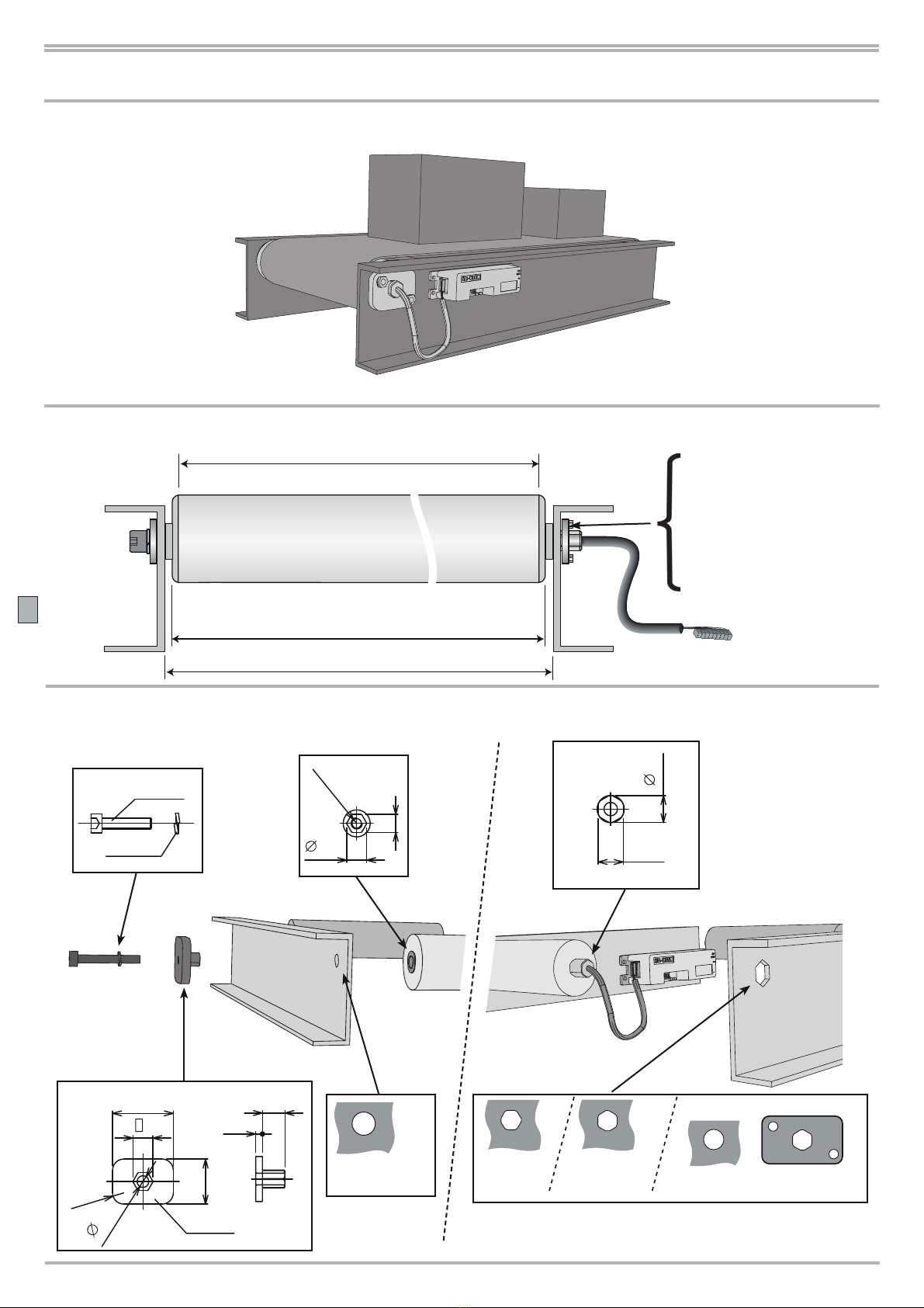
Coller sur le convoyeur l’étiquette fournie
pour faciliter la maintenance.
Attach the motor identity label provided
to the conveyor frame.
PRECAUTIONS D’EMPLOI CAUTION WHEN HANDLING
VORSICHTSMASSNAHMEN BEI DER HANDHABUNG
PRECAUCIÓNES DE EMPLEO
Kleben Sie zur leichteren Wartung das mit-
gelieferte Etikett auf den Förderer auf.
Pegar sobre el transportador la etiqueta
producida para facilitar el mantenimiento.
CONDITIONS D’USAGE CONDITIONS OF USE
EINSATZBEDINGUNGEN CONDICIONES DE USO
PM320HS (32HS)
EMC Directive 2006/42/CE
6) Câble
Cable
Kabel
Cable
R mini = 18 mm
R
5)
F : Le rouleau moteur brushless (sans balai-collecteur)
nécessite l’utilisation d’une platine de commande livrée
avec le moteur. Celle-ci doit être protégée contre les
chocs et contre les inltrations d’eau et de poussière, en
fonction de son environnement (UTE C 15-103 : 97).
D : Für die Brushless-Motorrolle (bürstenlos) benötigen Sie
die mit dem Motor gelieferte Steuerplatine.
Diese muß gegen Stöße und Eindringen von Wasser und
Staub je nach Umgebung (HD 384.3S2:95 & 384.5-51S2:96)
geschützt werden.
E : The brushless motorized roller technology
necessitates that each Power Moller®is used in
conjunction with the circuit board supplied.This circuit
board must be protected from severe shocks and the
ingress of water / dust in accordance with European and
local regulations relevant to the installation.
SP : El rodillo motorizado brushless ( sin escobillas ) necesita
el uso de una
electronica de mando entregada con el Power
Moller®. Esta tiene que ser protegida contra los choques y las
inltraciónes de agua y polvo, en función del medio ambiente
(HD 384.3S2:95 & 384.5-51S2:96)
L’installation et le câblage du Power Moller®doivent être
réalisés dans les règles de l’art, en conformité avec les
normes locales en vigueur et les exigences de la Direc-
tive Machine 2006/42/CE.
Einbau und Verkabelung des Power Moller
®müssen nach den
Regeln der Kunst und in Übereinstimmung mit den vor Ort
gültigen Normen sowie den Anforderungen der Verordnung
Maschine 2006/42/CE erfolgen.
Installation and wiring must follow the Machinery Direc-
tive 2006/42/CE in addition to local regulations.
La instalación y el cableado del Power Moller®deben rea-
lizarse en conformidad con las reglas locales en vigor y las
exigencias de la directiva máquina 2006/42/CE.
Température /Temperature /Temperatur Temperatura
/ : 0°C / + 40°C
Humidité relative /Relative humidity /Luftfeuchtigkeit /Humedad relativa : < 90 %
Atmosphère ni corrosive ni explosive /Non corrosive and non explosive environments
Keine korrosive oder explosive Umgebung /Atmósfera ni corrosiva ni explosiva
Usage continu ou intermittent
( 1800 démarrages/heure )
Continuous or intermittent duty cycle
(1800 starts/hour)
/
Dauerbetrieb oder zyklischer Betrieb
( 1800 Takte/Stunde)
/Funcionamiento continuo o intermitente
(1800 arranques/ hora)
3) 4)1) 2)
ITOH DENKI EUROPE SA
Model 32HS10F0520/001
Date 02/07
Serial Nr 1151
IP 55
V 24 VDC
I 0.55 A
W 13.2 W
m/min 13.8
Service S1 OK
U1.2
Manuel utilisateur
Bedienungsanleitung
User manual
Manual de usuario
2
Non contractual document. We reserve the right to introduce modications that we consider useful, at any time. © ITOH DENKI
MODALITES D’INTEGRATION INSTALLATION GUIDELINES
EINBAUANWEISUNG CONDICIONES DE INTEGRACION
Du côté moteur, l’axe est bloqué
en rotation par la découpe hexa-
gonale du châssis ou par une
plaque spécique (non fournie).
L’axe libre doit être bloqué en
translation avec la plaque spéci-
que et une vis M5x22 mm.
Die Sechskantbohrung bzw.
eine Halterung (nicht mitge-
liefert) verhindert, daß sich
die Motorwelle in der Wange
dreht. Die kabelentgegenge-
setzte (freie) Achse muß mit
der Halterung und einer M5x22
mm Schraube blockiert werden, da-
mit sie sich nicht horizontal bewegt.
The shaft on the motor side is locked in
place by a hexagonal hole punched in the
frame or by a special bracket (not supplied).
The shaft on the non-motor side must be
locked in place using the special bush
and M5x22mm screw supplied.
Del lado motor, el eje está
bloqueado en rotación por el
recorte hexagonal del bastidor o
por un placa específica (no pro-
porcionada). El eje libre debe
estar bloqueado en traslado
con la placa específica y un tornillo
M5x22 mm.
DIMENSIONS DIMENSIONS /DIMENSIONEN DIMENSIONES
/
/
L
B= L + 12mm
A = L + 6 mm
Plaque avec perçage
hexagonal (non fournie)
Bracket with hexagonal
hole (not supplied)
Halterung mit Sechskant-
bohrung (nicht geliefert)
Placa con recorte hexa-
gonal
AXES SHAFTS /ACHSEN EJES
/
/
10
3
20
9
27
R5
5,2
Plaque
9
Rondelle
M5x22
11,1
12
9
8
M5x7
Ø9,1 mm
Hexa
11,2 mm
Hexa
11,2 mm Hexa 11,2 mm
+
Ø12,1 mm
(1)
(1)
rondelle
disc
Scheibe
disco
(2)
plaque
plate
Platte
placa
U1.2
MONTAGE DU POWER MOLLER®MOUNTING THE POWER MOLLER ®
MONTAGE POWER MOLLER ®MONTAGE DEL POWER MOLLER ®
1. Préparer le châssis du convoyeur pour le mon-
tage des rouleaux.
1. The conveyor frame should be drilled or punched
to accommodate the rollers.
1. Bereiten Sie den Förderrahmen für den Einbau der
Rollen vor.
1. Preparar el bastidor del transportador para el montaje
de los rodillos.
2. Monter les Power Moller®: enler le
câble sans l’endommager dans le trou du
châssis.
2. Einbau des Power Moller®: Führen
Sie das Kabel durch die Bohrung im
Seitenprofil, ohne es zu beschädigen.
2. Mount the Power Moller®in the frame by
rstly inserting the supply cable through the
frame hole taking care not to damage it.
2. Montar los Power Moller®: pasar el cable en
el agujero correspondiente, teniendo cuidado de
no dañarlo.
3. Placer la plaque de xation dans le châssis et
l’axe libre du rouleau. Immobiliser la plaque avec
une vis M5 x 22 mm équipée d’une rondelle à dents.
3. For the of the non-cabled side, insert the bush through
the frame hole into the endcap. Secure the bush using
the M5x22mm screw and split washer.
3. Setzen Sie die Halterung und die freie Achse in den
Förderrahmen. Halten Sie die Halterung mit einer M5 x
22 mm Schraube mit Zahnscheibe fest.
3. Colocar la placa de fijación en el bastidor y el eje libre del
rodillo. Inmovilizar la placa con un tornillo M5 x 22 mm equi-
pada con una arandela a dientes
Caution : Prevent risk of shearing the cable.
Achtung : Beugen Sie der Gefahr von Kabelbruch vor .
4. Serrer la vis M5 pour bloquer l’axe libre du Power Moller®.
4. Ziehen Sie die M5-Schraube fest, um die freie Achse des Power
Moller®zu blockieren.
4. Tighten the M5 screw to secure the non-cabled side of the
Power Moller®.
4. Apretar el tornillo M5 para bloquear el eje libre del Power Moller®.
Attention : Prévenir tout risque de cisaillement du câble.
Cuidado: Prevenir todo riesgo de cizalladura del cable.
C = 30 Nm ±10%
Außervertragliches Dokument. Änderungen vorbehalten. © ITOH DENKI
3
U1.2
STEUERPLATINE
PLATINE DE COMMANDE CIRCUIT BOARD
ELECTRONICA DE MANDO
32
L
3030
L+6
L+12 12 300
12
31
BALLIGES MODELL
MODÈLE CYLINDRO-CONIQUE CROWNED MODEL
MODELO CILINFRO-CONICO
Utiliser la platine de commande CB018S pour piloter les
Power Moller®brushless PM320HS (32HS). Consulter la
notice livrée avec la platine avant tout essai du convoyeur.
Benutzen Sie die Steuerplatine
CB018S zur Steuerung des Power
Moller®PM320HS (32HS) Brushless.
Lesen Sie vor Gebrauch die Anleitung
der Platine.
Use the circuit board CB018S to control the Power Moller ®
brushless DC motors series PM320HS (32HS). Please consult
the installation instructions provided with the circuit borad
before any trials with the conveyor.
Utilizar la electrónica CB018S para pilotar el
Power Moller ®brushless PM320HS (32HS).
Consultar el folleto entregado ante todo
ensayo.
Alimentation TBTS 24V CC ± 10 % - une alimentation stabilisée est recommandée
SELV supply 24V DC ± 10 % - A stabilised supply is recommanded
Sicherheits-Kleinspannung 24V DC ± 10 % - Verwenden Sie ein Netzteil mit stabiler Stromzufuhr
Alimentación SELV 24 V CC ± 10 % - Una alimentacion estabilizada es recomendada
t
U (V)
Stop Run
24 V
OK
t
U (V)
24 V
Stop Run
MAINTENANCE
MANTENIMIENTO
TROUBLE–SHOOTING
WARTUNG
1. Vérier périodiquement le serrage des vis des plaques
de xation et des borniers.
2. Nettoyage : éviter tout produit détergent.
3. En cas d’appel SAV : relever les n° du modèle et de
série de l’étiquette.
4. En cas d’expédition du Power Moller®, protéger les
axes et le câble contre les chocs axiaux.
1. Überprüfen Sie regelmäßig, ob die Schrauben der Stützen
und Klemmen gut festgezogen sind.
2. Reinigung : Vermeiden Sie Putzmittel.
3. Bei Anruf des Kundendiensts : notieren Sie Modell- und
Seriennummer des Power Moller
® .
4. Bei Versand des Power Moller ®sichern Sie die Achsen und
das Kabel gegen Stöße ab.
1. Periodically check brackets, shafts and connectors are
securely tightened.
2. Cleaning : do not use detergents.
3. After Sales Service : please note the model and series
numbers from the motor identity label on the conveyor frame.
4. If returning the Power Moller®, protect shafts and cable
from impact damage.
1. Veri car periodicamente si lajación esta bien apretada.
2. Limpieza: evitartodos los productos detergentes.
3. Para lasllamadas de SAV: usar los n° del modelo de serie del Power
Moller®
.
4. En caso de envio del Power Moller®, proteger los ejes y el cable
contra los choques axiales.
ITOH DENKI EUROPE SAS
http://www.itoh–denki.com
France
490 avenue des Jourdies
PAE les Jourdies - BP 323
74807 St Pierre en Faucigny Cedex
Tel : 33 (0)4 50 03 09 99
Fax : 33 (0)4 50 03 07 60
info@itoh–denki.com
UK
info@itoh–denki.com
SAS au capital de 460 000 Euros - SIRET 343 034 344 000 30 - Code APE 4669B - RCS ANNECY 1987 B 80413 - EORI N° : FR34303434400030
Deutschland
[email protected]
idomsalelridañaedotnemomreiuqlaucneohceredlesomavresérsoN.lautcartnoconotnemucoD caciónes que juzgaremos utiles. © ITOH DENKI
4
U1.2

This manual suits for next models

1

Other ITOH DENKI DC Drive manuals

ITOH DENKI PM 500 FS User manual

ITOH DENKI

ITOH DENKI PM 500 FS User manual

ITOH DENKI CB-016BP7 User manual

ITOH DENKI

ITOH DENKI CB-016BP7 User manual

ITOH DENKI CBM-105 FN User manual

ITOH DENKI

ITOH DENKI CBM-105 FN User manual

ITOH DENKI POWER MOLLER 24 HB-510N User manual

ITOH DENKI

ITOH DENKI POWER MOLLER 24 HB-510N User manual

ITOH DENKI POWER MOLLER HBV-609 Guide

ITOH DENKI

ITOH DENKI POWER MOLLER HBV-609 Guide

ITOH DENKI POWER MOLLER 24 HBM-604BN User manual

ITOH DENKI

ITOH DENKI POWER MOLLER 24 HBM-604BN User manual

ITOH DENKI CB-016 series User manual

ITOH DENKI

ITOH DENKI CB-016 series User manual

ITOH DENKI POWER MOLLER HBM-604BN User manual

ITOH DENKI

ITOH DENKI POWER MOLLER HBM-604BN User manual

ITOH DENKI POWER MOLLER 24 CBM-103FN User manual

ITOH DENKI

ITOH DENKI POWER MOLLER 24 CBM-103FN User manual

ITOH DENKI Power Moller 24 CBM-105FN User manual

ITOH DENKI

ITOH DENKI Power Moller 24 CBM-105FN User manual

ITOH DENKI POWER MOLLER 24 HBK-608FN User manual

ITOH DENKI

ITOH DENKI POWER MOLLER 24 HBK-608FN User manual

ITOH DENKI CB-016BP7 User manual

ITOH DENKI

ITOH DENKI CB-016BP7 User manual

Popular DC Drive manuals by other brands

Philips ED52CDRW manual

Philips

Philips ED52CDRW manual

Toshiba APOGEE FLN APG001Z instruction manual

Toshiba

Toshiba APOGEE FLN APG001Z instruction manual

Becker EVO 20 R PLUS BT Assembly and operating instructions

Becker

Becker EVO 20 R PLUS BT Assembly and operating instructions

Siemens SINAMICS S120 Commissioning manual

Siemens

Siemens SINAMICS S120 Commissioning manual

Eskridge 50L Service manual

Eskridge

Eskridge 50L Service manual

Nidec NE200 Series user manual

Nidec

Nidec NE200 Series user manual

Sensia CD20 user manual

Sensia

Sensia CD20 user manual

ISOMET RFA920T Series manual

ISOMET

ISOMET RFA920T Series manual

SOMFY ILMO2 50 io instructions

SOMFY

SOMFY ILMO2 50 io instructions

Lenze 8200 motec Mounting instructions

Lenze

Lenze 8200 motec Mounting instructions

Danfoss VLT AutomationDrive FC 360 Programming guide

Danfoss

Danfoss VLT AutomationDrive FC 360 Programming guide

Parker 890SD Engineering Reference

Parker

Parker 890SD Engineering Reference

GFA ELEKTROMAT SI 35.100 FU-40,00 installation instructions

GFA

GFA ELEKTROMAT SI 35.100 FU-40,00 installation instructions

Emerson EV3 Series Application guidelines

Emerson

Emerson EV3 Series Application guidelines

Iomega REV 70 Quick install

Iomega

Iomega REV 70 Quick install

INVT GD350-2R2G--UL Operation manual

INVT

INVT GD350-2R2G--UL Operation manual

LSIS SV-iS7 series manual

LSIS

LSIS SV-iS7 series manual

Inovance AM600 Series user guide

Inovance

Inovance AM600 Series user guide

manuals.online logo
manuals.online logoBrands
  • About & Mission
  • Contact us
  • Privacy Policy
  • Terms and Conditions

Copyright 2025 Manuals.Online. All Rights Reserved.