Itowa GOLD User manual

GOLD
QUICK GUIDE
MAGRGOLDGB-REV.3-16/02/05 - M.E.C.
Approved by Engineering Manager: J. Varela. 1
QUICK GUIDE
SYNTHESIZED SET

GOLD
QUICK GUIDE
MAGRGOLDGB-REV.3-16/02/05 - M.E.C.
Approved by Engineering Manager: J. Varela.
2
DESCRIPTION OF THE SET
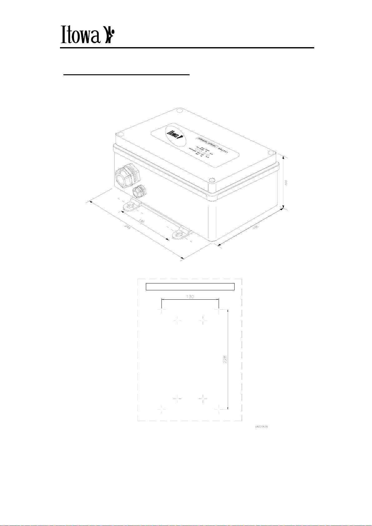
1.1. RECEIVER
POSITION OF THE HOLES FOR FIXATION

GOLD
QUICK GUIDE
MAGRGOLDGB-REV.3-16/02/05 - M.E.C.
Approved by Engineering Manager: J. Varela. 3
1.1.1. CONFIGURATION OF THE RECEIVER
A (Pos. OFF)
ZERO
The Zero Point. relay is activated when any command is
activated.
A
UXILIARY
A
uxiliary relay enabled.
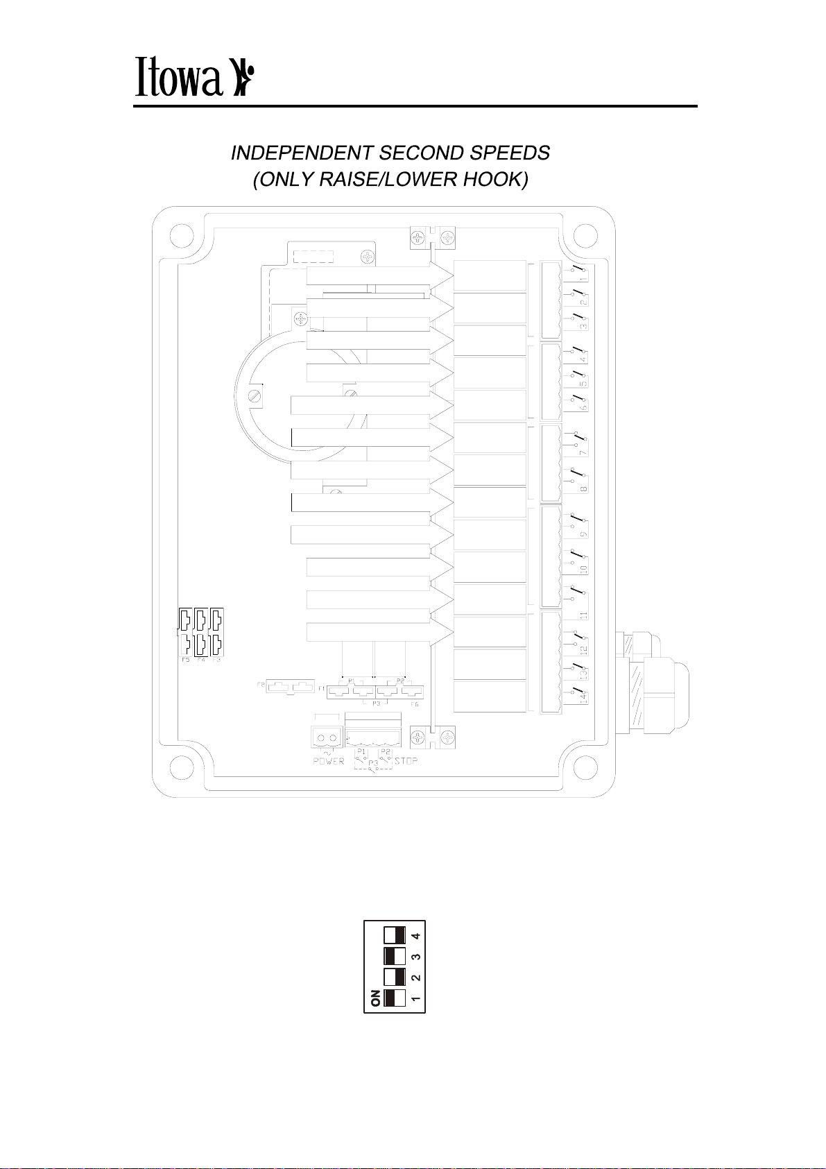
A (Pos. ON)
2nd INDEPENDENT SPEEDS
Changes the common second speeds configuration to
independent (Fig. 2). Options C and D are not available in
this mode.
D
C
B
A
D
C
B
A
B (Pos. ON)
A
NTAGONIC
When two opposite commands are pressed at the same time,
the relays involved will be automatically deactivated.
.
D (Pos. ON)
2nd INDEPENDENT SPEEDS (ONLY HOISTING)
Changes the configuration of the second speeds configuration
from common relays to independent. (Fig. 3). The minidip
A
should be in the OFF position to allow this configuration.
D
C
B
A
C (Pos. OFF)
A
UXILIARY
C (Pos. ON)
BISTABLE AUXILIARY BUTTON
Whenever the Auxiliary button is pressed, it switches the relay
status. The minidip A should be in the OFF position for this
configuration to be available.
D
C
B
A

GOLD
QUICK GUIDE
MAGRGOLDGB-REV.3-16/02/05 - M.E.C.
Approved by Engineering Manager: J. Varela.
4
1.1.2. RELAY OUTPUTS
Fig. 1. Configuration of 2nd Common Speeds
AUXILIARY
RELAIS RELAIS HORN
RAISE
START
RELAIS 12
RELAIS 11
RELAIS 10
RELAIS 9
RELAIS 8
RELAIS 7
RELAIS 6
RELAIS 5
RELAIS 4
RELAIS 3
RELAIS 2
RELAIS 1
STOPSTOP
15 16
LOWER
TROLLEY LEFT
TROLLEY RIGHT
CRANE FORWARDS
2nd SPEED HOISTING
2nd SPEED TROLLEY
2nd SPEED CRANE
CRANE BACKWARDS
ZERO POINT
Va000839
D
C
B
A

GOLD
QUICK GUIDE
MAGRGOLDGB-REV.3-16/02/05 - M.E.C.
Approved by Engineering Manager: J. Varela. 5
Fig. 2. Configuration of 2nd independent speeds
RELAIS RELAIS HORN
2nd SPEED LOWER
2nd SPEED TROLLEY LEFT
2nd SPEED CRANE BACKWARDS
LOWER
TROLLEY LEFT
TROLLEY RIGHT
CRANE FORWARDS
2nd SPEED RAISE
2nd SPEED TROLLEY RIGHT
2nd SPEED CRANE FORWARDS
CRANE BACKWARDS
Va000840
START
RELAIS 12
RELAIS 11
RELAIS 10
RELAIS 9
RELAIS 8
RELAIS 7
RELAIS 6
RELAIS 5
RELAIS 4
RELAIS 3
RELAIS 2
RELAIS 1
STOPSTOP
15 16
RAISE
D
C
B
A
GOLD
QUICK GUIDE
MAGRGOLDGB-REV.3-16/02/05 - M.E.C.
Approved by Engineering Manager: J. Varela.
6
Fig. 3. Configuration of independent second speeds
only in hoisting speeds
START
RELAIS 12
RELAIS 11
RELAIS 10
RELAIS 9
RELAIS 8
RELAIS 7
RELAIS 6
RELAIS 5
RELAIS 4
RELAIS 3
RELAIS 2
RELAIS 1
STOPSTOP
15 16
AUXILIARY
RAISE
LOWER
TROLLEY LEFT
TROLLEY RIGHT
CRANE FORWARDS
2nd SPEED RAISE
2nd SPEED TROLLEY
2nd SPEED CRANE
CRANE BACKWARDS
ZERO POINT
Va000841
RELAIS RELAIS HORN
2nd SPEED LOWER
D
C
B
A

GOLD
QUICK GUIDE
MAGRGOLDGB-REV.3-16/02/05 - M.E.C.
Approved by Engineering Manager: J. Varela. 7
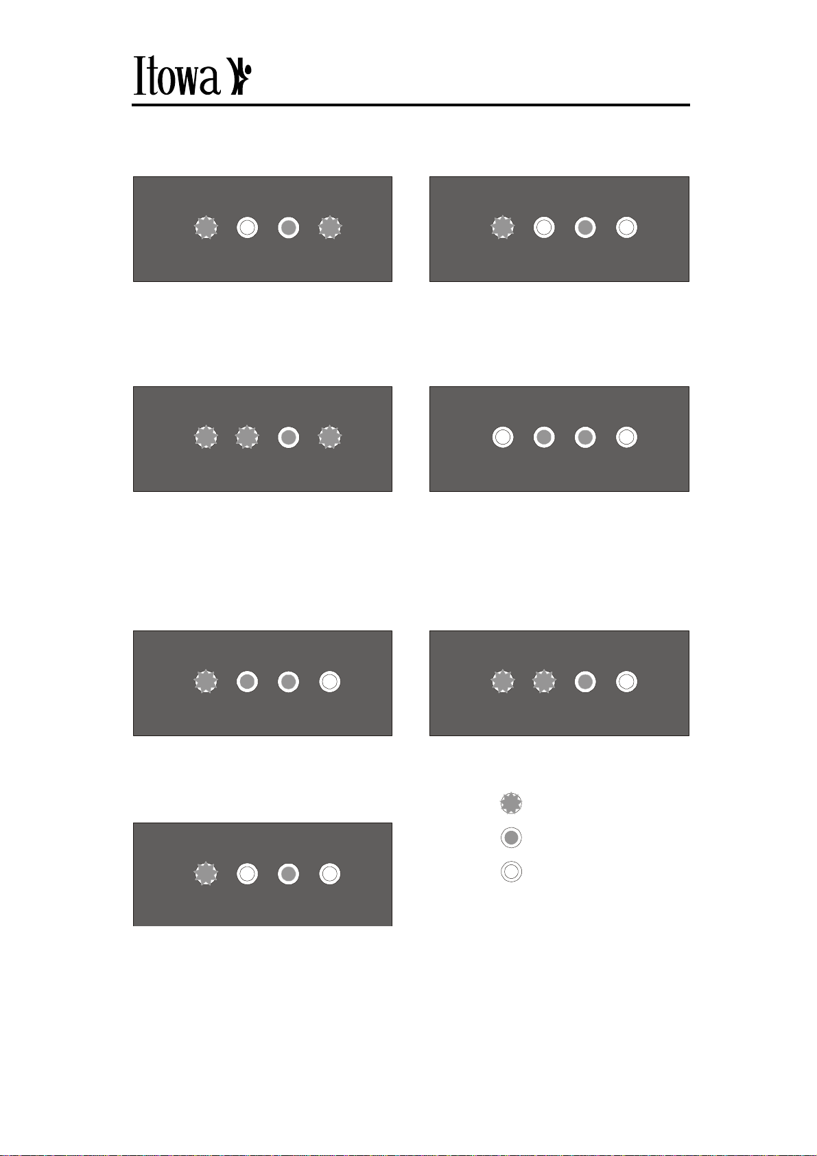
1.1.3. MESSAGES OF THE RECEIVER
• NORMAL OPERATION
• RECORDING THE KEY
When switched on, all the leds,
except the supply led, flash for a
few seconds
RUN FAILURE
RELAY POWER
OK Rx OK
FUNCIONANDO
RELE
FALLO ALIMENT.
OK
Rx OK
RUN FAILURE
RELAY POWER
OK Rx OK
FUNCIONANDO
RELE
FALLO ALIMENT.
OK
Rx OK
Signal reception OK
RUN FAILURE
RELAY POWER
OK Rx OK
FUNCIONANDO
RELE
FALLO ALIMENT.
OK
Rx OK
The leds flash when the key is
inserted
RUN FAILURE
RELAY POWER
OK Rx OK
FUNCIONANDO
RELE
FALLO ALIMENT.
OK
Rx OK
Recording OK.
Recording NOT OK
RUN FAILURE
RELAY POWER
OK Rx OK
FUNCIONANDO
RELE
FALLO ALIMENT.
OK
Rx OK
RUN FAILURE
RELAY POWER
OK Rx OK
FUNCIONANDO
RELE
FALLO ALIMENT.
OK
Rx OK
Display when the key is removed
GOLD
QUICK GUIDE
MAGRGOLDGB-REV.3-16/02/05 - M.E.C.
Approved by Engineering Manager: J. Varela.
8
• CHANGING THE FREQUENCY
• ANOMALIES
RUN FAILURE
RELAY POWER
OK Rx OK
FUNCIONANDO
RELE
FALLO ALIMENT.
OK
Rx OK
If this message continues afte
r
switching on the power supply, it
means that there is a FAULT IN
THE E2PROM of the controller.
Contact the authorised technical
service.
RUN FAILURE
RELAY POWER
OK Rx OK
FUNCIONANDO
RELE
FALLO ALIMENT.
OK
Rx OK
FAULT IN THE DRIVERS.
Contact the authorised technical
service
RUN FAILURE
RELAY POWER
OK Rx OK
FUNCIONANDO
RELE
FALLO ALIMENT.
OK
Rx OK
FAULT IN THE STOP RELAYS.
Contact the authorised technical
service.
RUN FAILURE
RELAY POWER
OK Rx OK
FUNCIONANDO
RELE
FALLO ALIMENT.
OK
Rx OK
Receiver on stand-by fo
r
frequency change
RUN FAILURE
RELAY POWER
OK Rx OK
FUNCIONANDO
RELE
FALLO ALIMENT.
OK
Rx OK
Frequency change OK
RUN FAILURE
RELAY POWER
OK Rx OK
FUNCIONANDO
RELE
FALLO ALIMENT.
OK
Rx OK
POWER SUPPLY FAULT
RUN FAILURE
RELAY POWER
OK Rx OK
FUNCIONANDO
RELE
FALLO ALIMENT.
OK
Rx OK
NO RECEPTION SIGNAL, Keep
the button pressed for a
maximum of 20 seconds
Parpadeo
Encendido
Apagado
Flash
On
Off
GOLD
QUICK GUIDE
MAGRGOLDGB-REV.3-16/02/05 - M.E.C.
Approved by Engineering Manager: J. Varela. 9
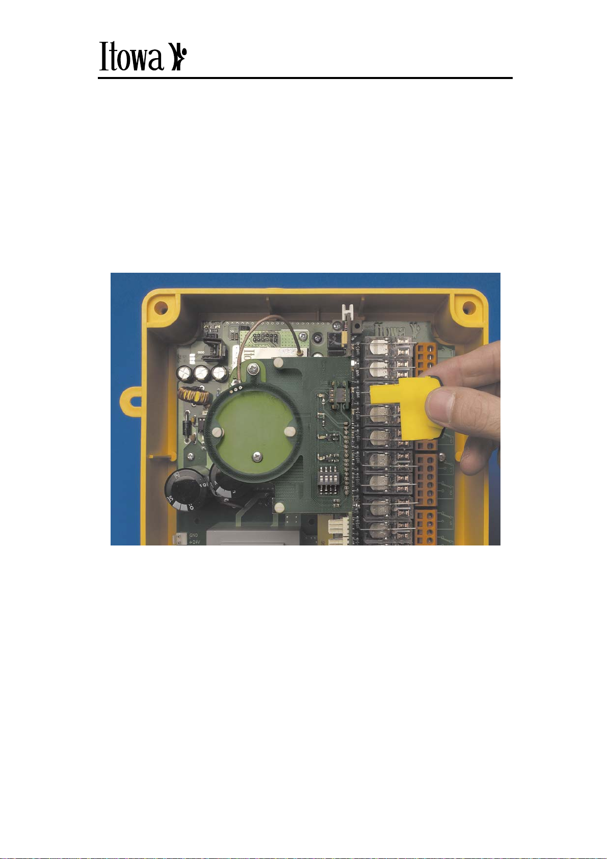
1.1.4. RECORDING THE KEY FROM THE RECEIVER
To match the transmitter and the receiver, the key is removed from the
transmitter and is inserted in the slot of the receiver controller next to the
minidips. Depending on how the key is recorded, the corresponding message
will appear (see section Receiver Messages). This will mean that the
transmitter has the same set code and channel as the receiver. When
recording the key, the frequency change mode will be set in automatic.
Fig. 4: Recording the key
Table of contents
Other Itowa Receiver manuals


