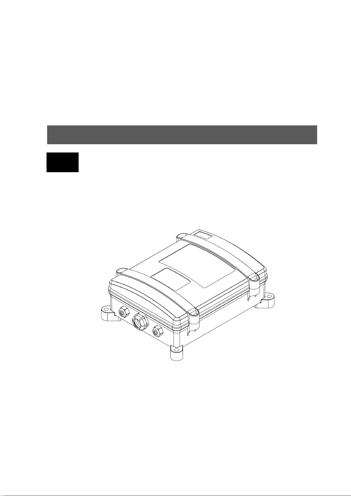
Itowa IT3G7R20 User manual

User's manual
MARI20EN –Rev.1 –03/2021
EN
Receiver IT3G7R20

Receiver IT3G7R20
USER'S MANUAL
2
ANY REPRODUCTION OF ALL OR PART OF THIS MANUAL IS STRICTLY FORBIDDEN
WITHOUT PRIOR WRITTEN PERMISSION FROM ITOWA.
OTHERWISE, ITOWA RESERVES THE RIGHT TO TAKE SUCH ACTION AS IT DEEMS
APPROPRIATE UNDER CURRENT LEGISLATION.
ITOWA RESERVES THE RIGHT TO MODIFY THIS MANUAL WITHOUT PRIOR NOTICE.

Receiver IT3G7R20
USER'S MANUAL
3
INDEX:
1. INTRODUCTION 4
2. GENERAL TERMS AND CONDITIONS FOR THE CORRECT & SAFE USE OF THE RECEIVER 4
3. DESCRIPTION OF THE RECEIVER 5
3.1. GENERAL DESCRIPTION 5
4. TECHNICAL FEATURES 6
4.1. GENERAL CHARACTERISTICS 6
5. INSTALLATION AND START-UP 7
5.1. INSTALLATION OF THE RECEIVER 7
5.2. CONNECTION 7
5.3. START-UP 9
6. RECEIVER MAINTENANCE 10
7. WORKING CHANNEL DISPLAY 11
8. FREQUENCY SCANNING 12
9. LED INFORMATION 13
10. POSSIBLE INCIDENTS AND SOLUTIONS () 15
11. RECYCLING 17
11.1. PACKAGING 17

Receiver IT3G7R20
USER'S MANUAL
4
1. INTRODUCTION
The manual you have in your hands is a guide to the correct use of the ITOWA IT3G7R20 multi-
frequency receiver.
This receiver, together with the associated remote control, is specially designed to be controlled remotely,
without cables, and to act directly on electromechanically driven machinery.
The radio signals used employ FM frequency modulation and FFSK coding. The most advanced
technology and state-of-the-art microprocessors have been used in the electronic design.
In order to avoid undesired manoeuvres, the receiver is equipped with various safety mechanisms, which
will be described in the following chapters. Any auto-detection of anomalies blocks the execution of
manoeuvres.
The receiver operates in the UHF band on frequencies between 433.050 and 434.775 MHz or between
868.000 and 870.000 MHz as prescribed by the I-ETS 300 220 telecommunications regulations.
Contact Itowa for other certificates.
2. GENERAL TERMS AND CONDITIONS FOR THE CORRECT & SAFE
USE OF THE RECEIVER
In order to have the maximum security in the handling of the receiver, the operator must follow the rules
described in this manual.
When carrying out any manoeuvre on the machine, the operator must be located in a place where he has
a view of the manoeuvre being carried out at all times. If this is not possible, the operator must be located
in a place that allows him to see the maximum possible maneuver and in the hidden places he must use
an assistant. Never carry out a manoeuvre that may have an uncontrolled part.
When the operator finishes his work on the receiver, he must lock the EMERGENCY STOP BUTTON of
the transmitter and must take care not to leave the control of the machine accessible to unauthorised
personnel.

Receiver IT3G7R20
USER'S MANUAL
5
3. DESCRIPTION OF THE RECEIVER
3.1. GENERAL DESCRIPTION
The reception unit is composed of a watertight plastic housing (IP65) inside which the various electronic
systems for receiving orders and activating/deactivating the appropriate relays for each machine
operation are located.
This model of receiver, thanks to its robust design, can be used in a multitude of applications, both
indoors and outdoors.
The receiver assembly can be divided into three blocks (Fig. 3-1), UHF receiver, control circuit and relay
circuit.
Fig. 3-1. Block diagram of the receiver
The signal received by the antenna is injected to the receiver, which supplies the microprocessor with a
low frequency signal in FFSK code. The control module is responsible for checking that the information
received is free of errors, then elaborating the pertinent orders to activate the appropriate relay.
In case of equipment malfunction, specific control circuits are responsible for deactivating the receiver's
working operations.
For greater safety, all monitoring circuits are duplicated.
UHF
RECEIVER
CONTROL
CIRCUIT
TO SWITCHING
CONTACTORS
RELAY
CIRCUIT

Receiver IT3G7R20
USER'S MANUAL
6
4. TECHNICAL FEATURES
4.1. GENERAL CHARACTERISTICS
System:
MULTI-FREQUENCY
Frequency:
ISM-BAND
Order response time:
<50 ms
Active emergency time:
<50 ms
Passive emergency time:
500 ms
Range of action:
100 meters
Temperature range:
From -20 to 70 ºC
Frequency bands:
433.050 to 434.775 MHz
868.000 to 870.000 MHz
I-ETS 300 220
Sensitivity:
0,3 µV
Image frequency rejection:
> 65 dB
Protection against intermodulation:
> 65 dB
Rejection to adjacent channel:
> 65 dB
Available maneuvers:
20 RELAYS + 2 STOP RELAYS
Maximum relay switching capacity:
Resistive load:
Inductive load:
(cosØ=0,4)
8 A at 250 Vac or 30 Vdc
3 A at 250 Vac or 4 A at 30
Vdc
Number of commutations:
Resistive load:
Inductive load:
(cosØ=0,4)
105maneuvers
105maneuvers
Power supply (depending on model):
48 - 230 Vac (-20% + 15%) according to EN 60047-5-1
Max. Consumption:
100 mA (230 Vac)
300 mA (115 Vac)
600 mA (48 Vac)
Fuses:
Emergency Stop Maneuver: 8 A
Connection:
Using a terminal strip
External dimensions:
285 x 220 x 100 mm
Fixation:
Screw (standard)
Weight:
With standard fixing: 1.350 gr.
Protection:
IP65
Security level:
Category 4 –SIL3 / PLe according to EN ISO 13849

Receiver IT3G7R20
USER'S MANUAL
7
5. INSTALLATION AND START-UP
5.1. INSTALLATION OF THE RECEIVER
The receiver should be located in an easily accessible area so that it can be easily handled. The antenna
should be pointing towards the ground and in a protected place to avoid shocks.
In compliance with Royal Decree 171/2004 on the Coordination of Business Activities, you are reminded
that you must guarantee the safety conditions for the maintenance of the machine in question, especially
in terms of its accessibility and transit areas to the points where the operator must carry out his work. (
1
)
ATTENTION!: IT IS VERY IMPORTANT TO CLOSE THE COVER OF THE RECEIVER
CORRECTLY IN ORDER TO ENSURE THAT IT IS WATERTIGHT, AS THE ENTRY OF
WATER CAN SPOIL IT. THE WARRANTY DOES NOT COVER FAULTS RESULTING
FROM IMPROPER CLOSING OF THE COVER.
Whenever the installation allows it, the antenna should be free of metal shields to achieve a better radio
link and avoid communication cuts.
Itowa is not responsible for improper installation.
5.2. CONNECTION
It is recommended to connect the receiver with a standardized multi-cable hose. This hose will be
connected to the receiver from one end via the strip on the base plate of the machine, while the other end
will be fitted with a multi-pin connector, identical to the one used by the machine to interconnect with its
conventional pushbutton panel.
ATTENTION!: THE CONNECTION MUST BE MADE IN SUCH WAY THAT WHEN THE
MAIN SWITCH IS TURNED OFF, THE RECEIVER IS ALSO TURNED OFF.
ATTENTION!: AS A SAFETY MEASURE IT IS ESSENTIAL TO ENSURE AN EARTH
CONNECTION VIA THE CORRESPONDING PIN OF THE CONNECTOR.
The standard receiver can be powered by a voltage in the range of 48 to 240 Vac.
For more details on the wiring of the relays associated with the controls, please refer to the relay output
sheet supplied with the receiver.
1
Applicable only in Spain

Receiver IT3G7R20
USER'S MANUAL
8
Fig. 5-1. Receiver connection
Relay outputs Generic:
RELAY
1
2
3
4
5
6
7
8
9
10
NA
NA
NA
NA
NA
NA
NA
NA
NA
NA
MANEUVER
P1
P2
P3
P4
P5
P6
P7
P8
2nd P1
2nd P2
RELAY
11
12
13
14
15
16
NA
NA
NA
NC
NA
NC
NA
NC
NA
NC
MANEUVER
2nd P3
2nd P4
2nd P5
--
2nd P6
--
2nd P7
--
2nd P8
--
RELAY
17
18
19
20
NA
NC
NA
NC
NA
NC
NA
NC
MANEUVER
AUX 1
--
AUX 2
--
AUX 3
--
AUX 4
--
RELAY
STOP 1
STOP 2
MANEUVER
STOP 1
STOP 2
Table 5-1. Connection of relays and maneuvers associated with the
'generic' receiver as an example. Where Px corresponds to the
customisable manoeuvres.
Specific output documentation is supplied with the unit.

Receiver IT3G7R20
USER'S MANUAL
9
Itowa is not responsible for improper installation.
5.3. START-UP
Once the receiver is installed and connected, when the main switch of the machine is activated, the red
LED located on the motherboard of the receiver equipment will light up, so it’s necessary to open the
cover of the receiver if you wish to verify its operation.
The following steps will be carried out with the remote control associated with the receiver:
Insert a charged battery into the remote control, unlock the STOP button and press the START1) button.
The receiver will start operating by activating the stop and run relays, and the main contactor will be2) latched.
From this moment on, pressing any button will activate the corresponding manoeuvre. The selected3) manoeuvre will remain active as long as the button remains pressed. The LEDs on the remote control
and on the LINK of the receiver will flash every time a manoeuvre signal is sent from the transmitter
and received by the receiver.
To keep the radio channel free and prevent the operator from accidentally leaving the machine running
when not in use, the remote control has been fitted with an automatic stop system. If no action is taken,
this system reacts after 180 seconds (configurable) by sending a stop sequence to the receiver, which will
make the machine stop.

Receiver IT3G7R20
USER'S MANUAL
10
6. RECEIVER MAINTENANCE
The receiver you have purchased is manufactured with top quality materials that ensure perfect
functioning and operation. Like any other machine or equipment, this receiver requires a minimum basic
attention that should be respected. In order to increase the lifetime of your receiver as much as possible,
and to avoid unnecessary repair costs, we recommend that you strictly follow the following maintenance
and preservation tips:
Use the mounting accessories properly and adjust them so that the receiver can be used comfortably
and safely.
Avoid unnecessary impacts.
It’s advisable not to leave the receiver unnecessarily exposed to the sun's rays.
ATTENTION!: FOR ANY REPAIRS, ORIGINAL SPARE PARTS MUST BE USED AND
UNDER NO CIRCUMSTANCES THE SAFETY FEATURES OF THE RECEIVER MUST
BE ALTERED.
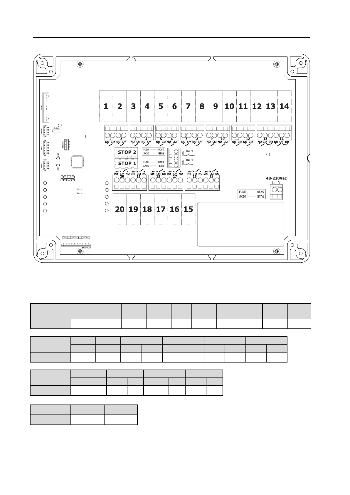
For the maintenance of the receiver, the following parts shall be checked:
The connection between the receiver and the machine's electrical equipment.
The correct functioning of the active and passive safety circuits.
The correct operation of all LEDs through the start-up test.
The correct fixing of the entire assembly and the correct closing of the cover and cable glands.
If you have an external antenna, check that the connection is clean and free of rust.
To check the function of the active safety, it’s sufficient to operate the STOP BUTTON on the transmitter
while the transmitter is running. The main contactor must drop out immediately.
To check the operation of the passive safety, disconnect the power supply or battery from the transmitter.
The general contactor must drop out after 0.5 seconds..
ATTENTION!: IF ANY ANOMALY IS DETECTED IN THE OPERATION OF THE
RECEIVER, IT MUST BE PUT OUT OF SERVICE IMMEDIATELY.
ATTENTION!: BEFORE ANY MANIPULATION PROCEED TO DEACTIVATE THE MAIN
SWITCH OF THE MACHINE.
If you have any questions or doubts, please do not hesitate to contact our Technical Assistance Service
or any of our authorised technicians.

Receiver IT3G7R20
USER'S MANUAL
11
7. WORKING CHANNEL DISPLAY
It’s important to know the frequency channel you are working on when making a frequency change or
detecting possible interference from other devices on the communication between the transmitter and the
receiver.
To find out the frequency channel of the receiver, you must follow these steps:
Switch on the receiver by unlocking the STOP BUTTON from the transmitter and activating start.
Engage the STOP BUTTON to switch to the standby state. At this point the receiver will indicate the
working channel using the LEDs.
First the LINK LED (see Fig. 9 1) will flash as many times as there are tens in the frequency channel.
When the display of the tens is finished, the RUN LED (see Fig. 9 1) continues to display the units of the
working channel.
If an attempt is made to start the equipment while the channel is being displayed, it will be given
preference, the channel display will be stopped and the receiver will be started.
At the end of a frequency change, the receiver also displays the new working channel.

Receiver IT3G7R20
USER'S MANUAL
12
8. FREQUENCY SCANNING
The receiver has some systems for detecting anomalies in the event that other equipment or systems
interfere with the communication between the transmitter and the receiver. These systems include
frequency scanning, which will be used to scan the entire band and find the frequency channels that are
or have been occupied by some other device emitting within the same band.
By finding the channels that are or have been occupied, by deduction, it’s possible to know which ones
are free and, therefore, it’s convenient to configure one of them to avoid these anomalies.
While the receiver is in standby, it performs a scan of the free and occupied channels of the entire band.
If the scanned channel is occupied, it will check whether the signal is its own or from another device. If it’s
recognised as its own, the working channel will be updated with the new configuration and work will
continue with this new working channel.
If there is no signal recognised as its own on the scanned channel, it will simply proceed to register
whether the channel is occupied or free.
The occupied channel status will prevail over the free channel status, which means that as soon as a
channel is found to be occupied it will be recorded as such even if it’s found in a later scan to be free.
This recording will be deleted as soon as the receiver is no longer supplied with power.

Receiver IT3G7R20
USER'S MANUAL
13
9. LED INFORMATION
The LEDs are located inside the unit and to view them, the top cover of the receiver must be removed.
Each of the relays has an associated LED that lights up when the corresponding relay is activated.
The rest of the LEDs are distributed on the main board as shown in the following figure:
Fig. 9-1. LEDs location
ICON
INDICATION
LED off.
Slow blinking.
LED off with rapid blinking on.
LED on with rapid blinking off.
LED on steady.
RELAY LED (red)
indicates relay power
supply.
LINK and RUN LED
The RUN LED (red) is lit
when the device is
operating correctly.
The LINK LED (green)
flashes every time a
radio signal is
successfully received
from the transmitter.
PWR LED indicating
receiver power
supply.

Receiver IT3G7R20
USER'S MANUAL
14
When the device is initialized and whenever it is stopped with the STOP button or by time, the
working channel is indicated by pulses on the LINK and PWR LEDs (tens and units respectively).
At the end of the band scan, it displays the channels that have been found to be free.
While the code or channel is being displayed, the unit can be started, which will stop the display and
switch to the normal running display status.
STATUS
LED RUN
Receiver in operation.
Failure in serial drivers.
Shutdown due to lack of radio frequency signal.
Failure in stop relays.
Receiver stops due to time or STOP BUTTON.
STATUS
LED LINK
Resting status or manoeuvre without changes.
EEPROM error.
Flashing every change of state of one or more relays.
STATUS
LED RUN + LED LINK
Low power supply.
STATUS
LED RELAYS
Correct relay power supply.
Receiver at rest.
STATUS
LED PWR
Correct power supply.
No power supply.

Receiver IT3G7R20
USER'S MANUAL
15
10. POSSIBLE INCIDENTS AND SOLUTIONS (
1
)
1
Information on the transmitters is included to facilitate the diagnosis of the problem.
INCIDENT
STATUS
SOLUTION
The device does
not start
None of the transmitter
indicators (TX) and
/ (BAT) are illuminated.
Check key status or selector switch in ON position.
Check that the battery is correctly inserted.
Check the charge status of the battery or replace it
directly with a charged one.
Only the LED /
(BAT) of the transmitter lights
up.
The battery is empty and must be replaced with a
charged one.
The (TX) LED on the
transmitter lights up, but the
LINK LED on the receiver
does not light up.
Check that the channel of the transmitter and the
receiver are the same.
Keep the transmitter's start button activated until the
receiver is switched on (max. 1 minute). Do this as
near as possible to the receiver.
Both LEDs (TX) and
/ (BAT) of the
transmitter blink.
Transmitter with blocked keyboard. To unblock it,
follow the steps in the section "Keyboard blocking"
in the transmitters manual.
The LED , S2 or S3 of
the transmitter blinks
(depending on the model).
There is an active channel, check that all the
actuators of the transmitter are in the rest position.
One of the LEDs in the
transmitter makes two rapid
blinks and a pause.
A contact of the STOP button has broken down,
notify the Technical Assistance Service.
None of the indicators on
the receiver light up.
Check that the power supply of the receiver is
correct and that it’s connected correctly.
The LINK LED on the
receiver flashes and then
the receiver is reset.
EEPROM error. Check if it is correctly inserted in its
socket. If it is and it still does not work, contact the
Technical Assistance Service.
Transmitter and
receiver start but
the machine does
not work.
The receiver is connected
to the machine but the
machine is still not working.
Check fuses in receiver. If a fuse has blown, it must
be replaced with a new one of the same value (see
value in section 4.1)
Check the connection of the hose from the receiver
to the machine's electrical panel using the
corresponding connectors.
Place the cable button panel/cab instead of the
remote control and if it doesn’t work either, the
problem lies with the machine.

Receiver IT3G7R20
USER'S MANUAL
16
ATTENTION!: ORIGINAL SPARE PARTS MUST BE USED FOR ANY REPAIRS AND
SAFETY FEATURES MUST NEVER BE ALTERED.
INCIDENT
STATUS
SOLUTION
After a change of
working channel
the machine is not
activated
The LINK LED on the
receiver lights up but the
receiver does not start up.
Keep the transmitter's start button activated until the
receiver is switched on (max. 1 minute). Do this as
near as possible to the receiver.
The receiver keeps the
LINK LED illuminated when
the transmitter is at rest.
There is interference on the new channel. You
should change to another channel and, if you don’t
receive the new channel, keep the start button on
the transmitter pressed (maximum 1 minute). Do
this as near as possible to the receiver.
The transmitter
doesn't allow a
change of
frequency
The indicators (TX) and
/ (BAT) don't blink
alternately.
Check battery charge status.
Check the set frequency change mode.
Incorrect input of
the working
channel on a
frequency change
Unwanted working channel
entered.
Repeat the entire process with the desired working
channel.
The remote control
has a short range
and even stops the
machine, but
allows it to be
reset.
Antenna disconnected,
broken or in poor condition
Replace the antenna or notify the Technical
Assistance Service.
Even if the transmitter is
switched off by locking the
STOP BUTTON, the
receiver still has the LINK
LED on.
There is interference from another device. The
working channel must be changed, following the
steps in the section "Frequency change" in the
transmitter's manual.
Randomly the
receiver is stopped
or some relays are
not activated, but
the receiver is still
running.
The RUN and LINK LED on
the receiver light up
alternately.
The receiver power supply is below 50% of the
nominal power supply.

Receiver IT3G7R20
USER'S MANUAL
17
11. RECYCLING
INFORMACIÓN PARA LA CORRECTA GESTIÓN DE LOS RESIDUOS DE APARATOS
ELÉCTRICOS Y ELECTRÓNICOS (RAEE)
At the end of the device's life, it shouldn't be disposed of mixed with general waste.
It can be delivered, free of charge, to specific collection centres, differentiated by the local authorities, or
to distributors who provide this service.
Separate disposal of electronic waste means avoiding possible negative consequences for the
environment, resulting from improper disposal, and allows for treatment and recycling of the materials that
compose it, obtaining significant savings in energy and resources.
TO UNDERLINE THE OBLIGATION TO COOPERATE WITH SEPARATE COLLECTION,
THE PRODUCT IS MARKED WITH A WARNING AGAINST THE USE OF TRADITIONAL
CONTAINERS FOR DISPOSAL.
For further information, please contact the relevant authorities.
11.1. PACKAGING
The materials used in the packaging are recyclable.
For the disposal of this type of waste, take into account the local regulations for the treatment of this
type of waste.

Receiver IT3G7R20
USER'S MANUAL
18
www.itowa.com
SINDITO, S.L.
Faraday, 159
08224 Terrassa (Barcelona)
Spain
Tel. +34 93 733 98 50
Table of contents
Other Itowa Receiver manuals