Itowa Mini RX User manual

USER MANUAL
MINI RECEIVER
WITH FIELD BUS


USER MANUAL
MINI RECEIVER
WITH FIELD BUS
ITOWA
MAMRBUSGB
REV 2
21/07/17
Approved by R+D Manager: X. Grau
IT IS FORBIDDEN TO FULLY OR PARTIALLY REPRODUCE THIS MANUAL, WITHOUT
THE PRIOR WRITTEN AUTHORISATION FROM ITOWA.
IN THE EVENT OF INFRINGEMENT, ITOWA RESERVES THE RIGHT TO TAKE THE
ACTION IT DEEMS NECESSARY, IN ACCORDANCE WITH CURRENT LAW.
ITOWA RESERVES THE RIGHT TO MODIFY THIS MANUAL WITHOUT PRIOR
NOTIFICATION


MINI RECEIVER WITH FIELD BUS
USER MANUAL
I
CONTENTS:
1. INTRODUCTION..............................................................................................................................1-1
2. DESCRIPTION.................................................................................................................................2-1
3. CONNECTION .................................................................................................................................3-1
3.1 INTERNAL CONNECTOR 3-1
3.2 EXTERNAL CONNECTOR 3-2
4. SETTING THE SLAVE (RECEIVER)...............................................................................................4-4
4.1 NODE ADDRESS 4-4
4.2 BAUD-RATE 4-4
4.3 I/O SETTING 4-5
4.4 BUS TERMINATION 4-6
5. SETTING THE MASTER..................................................................................................................5-1
5.1 GSD OR EDS FILE 5-1
5.2 DATA SETTING 5-1
6. RUNNING OPERATION ..................................................................................................................6-3
7. RECYCLING....................................................................................................................................7-1
7.1 PACKAGING 7-1


MINI RECEIVER WITH FIELD BUS
USER MANUAL
1-1
1. INTRODUCTION
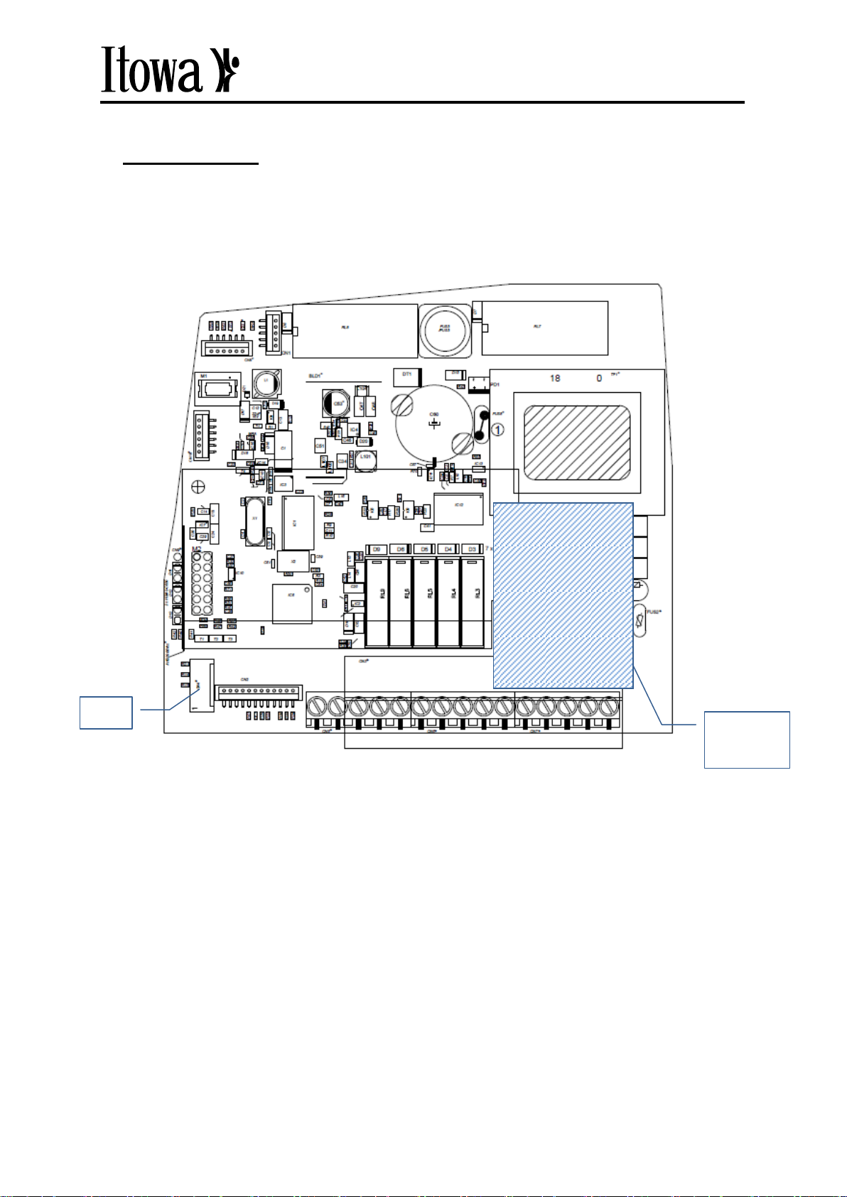
The Mini Receiver, which we will call hereafter Mini RX, has an expansion connector, CN4, which
enables the communication function with a fieldbus module. This module allows establishing links with
different types of bus, among which are: PROFIBUS, CANopen, DeviceNET, PROFINET,
ETHENET/IP and MODBUSTCP. The connection is made through a galvanic isolation and depending
on the type of bus, a different type of output is available in the equipment.
This external connection allows direct communication with a PLC, providing all the available
manoeuvres in the transmitters both at the digital level of contacts and at the analog level of
manipulators. In addition to the transmission of commands to the PLC, the equipment incorporates the
safety relays and allows the auxiliary connection of up to 6 contacts directly to the equipment.
The software, based on the REMOV019a version, allows managing both the configuration and the
communication with the network, adding new functionalities to the receiver, such as the increase of
available manoeuvres and the use of analog channels by copying the full functionality of the
transmitters.
The device configuration file is provided together with the device:
For PROFIBUS, the .gsd file is based on the HMS industrial networks standard for DP-V0 in
slave mode, and will be used later to configure the device within the network through the
master device, usually a PLC. Once configured, the PROFIBUS master will be able to read
the status of the different digital and analogue commands received from the transmitter.
For PROFINET, an .xml file is available which is based on the HMS Industrial Networks
GSDML standard for configuring the slave device on the network.
For the rest of field bus devices, the .eds file contains a description of the device, its functions,
and the object dictionary description that is implemented. This file is used by the network
configuration tools as previously set.


MINI RECEIVER WITH FIELD BUS
USER MANUAL
2-1
2. DESCRIPTION
The FIELD BUS expansion board is attached to CN4 and is arranged on the main board anchored to
one of the plate separators. The connection to the main board is shown in the figure, Fig. 1.
Fig.1.- Mini RX board.
The module receives the commands from the transmitter and retransmits the received information to
the master device of the fieldbus.
The absence of the module is automatically detected by the equipment, which waits for its connection
to start the normal operation of the equipment, since it is based on the transmission through the bus.
Once the equipment is installed, only the configuration in the network is necessary to begin to
exchange information with the system. In the following sections, the guidelines will be given to carry
out the installation and configuration on the network.
Field bus
module
CN4


MINI RECEIVER WITH FIELD BUS
USER MANUAL
3-1
3. CONNECTION
There are two possibilities for connecting the bus. The first one uses the standard wiring model
through the internal terminal strip, in which case the TUNNER receiver equipment is maintained in the
sealed condition and must be carried out as described in the following section "Internal Connection"
for intercommunication with the bus.
As a second option, you can use a TUNNER box that incorporates a female DB9 connector or an
RJ45 connector on the base of the housing. The "External Connection" section describes how to
connect to the BUS. In this case, having a non-leak proof opening, the safety condition against
humidity is lost for outdoor use and therefore its use is limited to an indoor installation.
3.1 INTERNAL CONNECTOR
When using the terminal block to connect the BUS, we will use the following diagrams according to
the type of bus available. Keep in mind that the bus cable must be separated from the power cable of
the equipment.
Fig.2.- Power connection for each model.
PROFIBUS diagram:
Fig.3.- PROFIBUS connection.

MINI RECEIVER WITH FIELD BUS
USER MANUAL
3-2
CANopen diagram:
Fig.4.- CANopen connection.
DeviceNET diagram:
Fig.5.- DeviceNET connection.
3.2 EXTERNAL CONNECTOR
A female DB9 connector is available at the base of the housing to connect PROFIBUS and CANopen;
Or an RJ45 connector for PROFINET, ETHERNET/IP and MODBUS TCP.
The pinout of the connectors for the different bus types are described below:

MINI RECEIVER WITH FIELD BUS
USER MANUAL
3-3
Fig. 6.- BUS connection to DB9 Fig. 7.- BUS connection to RJ45
PROFIBUS PINOUT:
PROFIBUS (DB9F) Connector
Pin
Signal
1
-
2
-
3
B-Line
4
RTS
5
GND BUS (isolated)
6
+5 V BUS (output, isolated, 100 mA
max.)
7
-
8
A-Line
9
-
Housing
Shield
CANopen PINOUT:
CANopen (DB9M) connector
Pin
Signal
1
-
2
CAN_L
3
CAN_GND
4
-
5
CAN_SHIELD
6
CAN_GND
7
CAN_H
8
-
9
-
Housing
CAN_SHIELD
PROFINET, ETHERNET/IP and MODBUSTCP PINOUT:
Ethernet (RJ45) Connector
Pin
Signal
1
TX+
2
TX-
3
RX+
4
-
5
-
6
RX-
7
-
8
-
Housing
SHIELD

MINI RECEIVER WITH FIELD BUS
USER MANUAL
4-4
.
4. SETTING THE SLAVE (RECEIVER)
In order to use the Mini RX as a network device, a logical and physical configuration is required to
accomplish with the appropriate communication conditions.
4.1 NODE ADDRESS
To establish communication between the device and the bus, you must first define the node address
in the device. The default address is 5, but the address can be modified by accessing the rotary
switches of the expansion board to set the tens and units of the address number. To do this, open the
equipment and access the selectors (Fig. 8).
Possible addresses range from 00 to 99 using each selector as a digit.
Fig. 8.- BCD rotary switches
In the case of Ethernet bus, the address of the module would become 192.168.0.XX where XX
corresponds to the value selected by the selectors on the board, from 00 to 99. The IP of the Ethernet
bus module does not necessarily have to be in range 192.168.0.x. It can be configured by disabling
the selectors to assign the desired IP through the network configuration software or through a specific
application "HMS-IPConfig" for IP assignment.
4.2 BAUD-RATE
It is not necessary to set a communication speed. The fieldbus expansion module is capable of
automatically detecting the communication speed through the bus.
For ETHERNET formats it operates at 10 or 100 Mbit.
Tens
Units

MINI RECEIVER WITH FIELD BUS
USER MANUAL
4-5
CANopen can operate between 20 kps and 1 Mbps.
The baud rates supported by PROFIBUS are as follows:
DeviceNET can operate with speeds of 125 kbps, 250 kbps y 500 kbps.
4.3 I/O SETTING
It is necessary to define in the receiver the amount of data that will be transmitted to the bus. Both the
size of bytes to be sent and those to be received are configured through the E2PROM memory. These
data are configured at the factory according to the needs of the customer.
The memory locations where the data is stored are (page 1):
0xA9
Number of digital output channels
0xAA
Number of analog output channels
0xAC
Number of digital input channels
0xAD
Number of analog input channels
0xAE
Set to 0x01 to activate auxiliary input (SCC 1 byte)
The “number of digital channels”corresponds to the resulting bytes of the channels, bit by channel
(digital channels/8). Each analog channel is one byte so the “number of analog channels”corresponds
to the quantity of analog channels.
Example:
If we use 24 digital channels and 6 analog channels we will have the follow:
Number of digital output channels = 24/8 = 3
Number of analog output channels = 6
9,6 kbps
187,5 kbps
6 Mbps
19,2 kbps
500 kbps
12 Mbps
45,45 kbps
1,5 Mbps
93,75 kbps
3 Mbps

MINI RECEIVER WITH FIELD BUS
USER MANUAL
4-6
4.4 BUS TERMINATION
If you need to use the device as the final line element for the PROFIBUS bus, you can activate the
end-of-line impedance by joining the 3 vertical jumpers of the expansion board.
Fig. 9.- Bus Termination.
Bus Termination
jumpers.

MINI RECEIVER WITH FIELD BUS
USER MANUAL
5-1
5. SETTING THE MASTER
5.1 GSD OR EDS FILE
Once the slave device, in this case the TUNNER receiver, has been configured and is ready to
operate, it is necessary to configure the device within the network. To do this, a GSD file, used by
Profibus and Profinet, is supplied with the equipment or an EDS file is provided for the other bus
types, which contain the parameterization data of the equipment for communication within the
network.
The available files are:
Profibus: itowa_01.gsd
Profinet: GSDML-V2.3-ITOWA-ABICPRT-20170612.xml
CANopen: EDS_ITOWA_COP_V_1_00.eds
DeviceNET: ITOWA000.eds
EtherNET/IP: EDS_ITOWA_EIP_V_3_0.eds
Modbus-TCP: EDS_ITOWA_EIP_V_3_0.eds
These files must be imported from the configuration interface of the master bus device to identify the
equipment and configure their properties. In this way the equipment is registered in the network and
the master can communicate with him.
5.2 DATA SETTING
Once the device parameters are loaded on the control interface of the master device, the inputs and
outputs of the master are configured according to the specifications of the frame allocation document
that is provided with the equipment.
When importing the GDS or EDS file into the configuration application, the device is incorporated into
the network and depending on the data to be used, the required input or output bytes are selected
from the configuration parameter catalogue.
For example to read 2 bytes in a Siemens S7 1200 PLC from an ITOWA device in a Profinet network,
the 2-byte block of input would be chosen in the Siemens TIA PORTAL configuration software. As
shown in Figure 10

MINI RECEIVER WITH FIELD BUS
USER MANUAL
5-2
Fig.10.- Data setting.
Subsequently, the programming of the PLC would be performed using the bits of this data input to
perform different maneuvers.
The frame allocation document: contains the layout of the data in bytes to be exchanged by the bus:
Fig. 11.- Document for data exchange.

MINI RECEIVER WITH FIELD BUS
USER MANUAL
6-3
In the case of digital signals, each bit of a byte will correspond to a maneouvre channel, while the
analog signals will occupy a whole byte to provide the assigned numerical value.
In the observation field of the document, the relevant characteristics will be indicated for each case
that needs it.
6. RUNNING OPERATION
Once the configuration has been made and the system is running, the equipment will transmit the
information of each action that occurs in the controller. The information is requested by the bus master
to read it.
The link to the bus will be active from the moment that equipment is started and will keep the
manoeuvre information updated with every change that is communicated through the radio
transmitter. When the radio communication is cut off, the data will be initialized and the information
received by the master will be null for the digital and analog channels. The more significant bit of
BYTE1 for the data frame of the fieldbus communication will indicate the state of running or stopping
of the transmitting equipment. The logic value 1 shall be maintained for the entire period that the
device is running and shall become 0 at the time the equipment is stopped.
When the equipment is started up, many software checks are carried out, in case that fieldbus module
is not detected, the equipment will not start and wait until the fieldbus access is available to start the
normal operation of the equipment.

Table of contents
Other Itowa Receiver manuals