Itowa IT3R16 User manual

USER MANUAL
RECEIVER
IT3R16


ITOWA
MARITGB
REV 2
10-01-2019
Approved by Engineering Manager: JM. Molina
IT IS FORBIDDEN TO FULLY OR PARTIALLY REPRODUCE THIS MANUAL, WITHOUT THE PRIOR
WRITTEN AUTHORISATION FROM ITOWA.
IN THE EVENT OF INFRINGEMENT, ITOWA RESERVES THE RIGHT TO TAKE THE ACTION IT
DEEMS NECESSARY, IN ACCORDANCE WITH CURRENT LAW.
ITOWA RESERVES THE RIGHT TO MODIFY THIS MANUAL WITHOUT PRIOR NOTIFICATION.


RECEIVER IT3R16
USER MANUAL
CONTENTS:
1. INTRODUCTION
1
2. GENERAL RULES FOR THE CORRECT AND SAFE USE OF THE RECEIVER
1
3. DESCRIPTION OF THE SET
2
4. TECHNICAL SPECIFICATIONS
3
5. INSTALLATION AND START - UP
5
5.1. INSTALLATION OF THE RECEIVER
6
5.1.1. STANDARD FASTENING OF THE RECEIVER
6
5.1.2. MAGNETIC FASTENING OF THE RECEIVER (OPTIONAL)
6
5.2. CONNECTIONS
7
5.3. POWER SUPPLY
8
5.4. START - UP
9
6. MAINTENANCE OF THE RECEIVER
9
7. WORKING CHANNEL DISPLAY
10
8. FREQUENCIES SCAN
11
9. POSSIBLE INCIDENTS AND SOLUTIONS
12
10. DISPLAY MESSAGES
13
11. RECYCLABILITY
14
11. 1. PACKAGING
16

RECEIVER IT3R16
USER MANUAL
1
1. INTRODUCTION
This user manual is a guide for the correct use of the ITOWA Multi-frequency RECEIVER IT3R16
correctly.
This receiver is specially designed for the wireless remote control of all types of electro-mechanical
machinery.
FM frequency and FFSK codification are used for the radio transmission of control signals. The most
advanced technology and the latest generation microprocessors have been incorporated in the
electronic design. This means total safety when using the radio control.
To avoid unwanted operations, the system is provided of several safety mechanisms that are
described further on. Operations are immediately blocked when any anomaly is automatically detected.
The receiver is working at UHF band, in frequencies between 433.050 and 434.775 MHz or 868.000
and 870.000 MHz as stipulated in the telecommunications legislation I-ETS 300 220
Please contact with Itowa for other certifications.
1.1. GCFI VERSION
GCFI version (Intelligent Changing Frequency Management) has been designed to enable an
intelligent change of non-occupied frequency, always automatically and at random. This system avoids
the possible interferences that can produce continuous stopping during the work.
NOTE:
ALL INFORMATION INCLUDED IN THIS MANUAL RELATED TO THE
CHANGE OF FREQUENCY AND TO THE WORKING CHANNEL, IS
NOT VALID FOR THIS VERSION OF EQUIPMENT.

RECEIVER IT3R16
USER MANUAL
2
2. GENERAL RULES FOR THE CORRECT AND SAFE USE
OF THE RECEIVER
For maximum safety when handling the receiver, the user must follow the rules described in this
manual.
To perform any operation of the machine, the radio control operator must be in a place where he can
view the whole manoeuvre being performed. If this is not possible, he should position himself where he
can see as much as of the manoeuvre as possible, and coordinate with another person when he
cannot see properly.. Never perform a manoeuvre which may be partially uncontrolled.
When the operator finishes the work over the receiver, he has to activate the Emergency Stop (PRESS
THE STOP BUTTON) on the transmitter and should try not to leave accessible the control of the
machine to unauthorized personnel.

RECEIVER IT3R16
USER MANUAL
3
3.RECEIVER DESCRIPTION
The receiver set consist of a cabinet which houses the various the different electronic systems to
receive the orders and to activate or deactivate the corresponding relays for each manoeuvre.
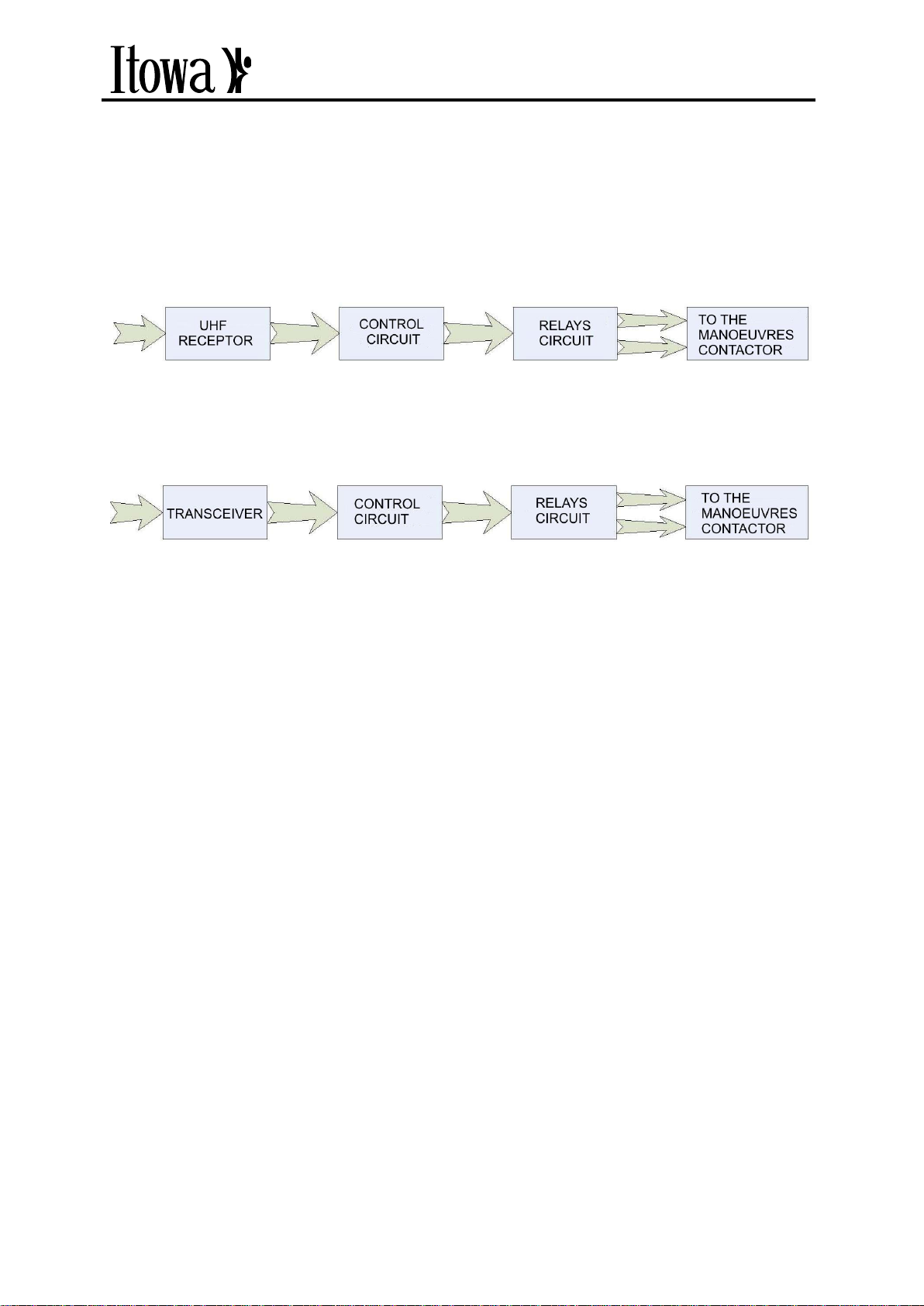
The receiver set can be divided in 3 blocks (Figure 3.1), UHF receiver, Control circuit and relays circuit.
FIGURE 3.1. DIAGRAM OF RECEIVER BLOCKS
For GCFI Version find below the blocks diagram :
FIGURE 33.2. DIAGRAM OF (GCFI) RECEIVER BLOCKS
The signal captured by the antenna is injected into the receiver, which supplies a low frequency signal
in FFSK code to the microprocessor. The control module is checking that the information received is
free of errors, developing then the corresponding orders to activate the appropriate relay.
In GCFI versions the receiver becomes a transceiver to establish a bidirectional communication with
the transmitter.
In case of malfunction, both hardware and software, in the control circuit they are provided specific
circuits that disable the working operations of the receiver.
To increase safety all monitoring circuits are bent.
It is a waterproof assembly (IP 65 protection) composed by highly resistant plastic material. Inside of it
has built-in the control electronic part & wiring of the receiver.
This model of receiver, due to its robust design, allows its location in multiple applications, both indoors
and outdoors.

RECEIVER IT3R16
USER MANUAL
4
FIGURE 3.3. IT3R16 RECEIVER VIEW

RECEIVER IT3R16
USER MANUAL
5
4. TECHNICAL SPECIFICATIONS
System
MULTIFREQUENCY
Frequency
ISM-BAND
Number of orders
Till 40 (option till 56)
Possibility of incorrect operation
10-18
Distance of Hamming
≥6
Programmable code
16777216
Order response time
<50 ms
Active emergency time
<50 ms
Passive emergency time
1600 ms
Radius of action
90 metros
Range of Temperature
De -20 to +70 ºC
Frequency Bands:
433.050 to 434.775 MHz
868.000 to 870.000 MHz
I-ETS 300 220
Sensibility:
0.3 µV
Image frequency rejection:
> 65 dB (TBD in GCFI versions)
Intermodulation protection:
> 65 dB (TBD in GCFI versions)
Adjacent channel rejection:
> 65 dB (TBD in GCFI versions)
Maximum capacity of relays switching:
Resistive charge:
Inductive Charge
(cosØ=0.4):
5 A to 250 Vac or 30 Vdc
2 A to 250 Vac or 30 Vdc
Power supply:
230 Vac (-20% + 15%) according to EN 60047-5-1
115 Vac (-20% + 15%) according to EN 60047-5-1
48 Vac (-20% + 15%) according to EN 60047-5-1
24 Vac (-20% + 15%) according to EN 60047-5-1
24 Vdc (-20% + 15%) according to EN 60047-5-1
Max. Consumption.
40 mA (230 Vac)
80 mA (115 Vac)
230 mA (48 Vac)
175 mA (24 Vac)
130 mA (24 Vdc)
Fuses:
Emergency stop manoeuvre
3 A
Connection:
By terminal strip
Dimensions:
Outside: 290 x 200 x 80 mm
Fastening:
By screws (standard) / Magnetic (optional)
Weight:
Standard fastening: 1.500 gr.
Magnetic fastening: 1.700 gr.
Protection:
IP65
Security level:
Category 4 –SIL3 / PLe according to EN ISO 13849

RECEIVER IT3R16
USER MANUAL
6
5. INSTALLATION AND START-UP
5.1. INSTALLATION OF THE RECEIVER
The receiver should be installed in an accessible location to be able to work on it easily.
* Remember, in accordance with Spanish Standard RD 171/2004 Coordination of Business Activities,
you must ensure security conditions for the maintenance of the machine in question, specially in its
accessibility and traffic areas to the points where the operator can carry out their work.
In applications when the antenna is outside, the antenna has to avoid metal screens to achieve a
better radio link and avoid failures in communication.
5.1.1. STANDARD FASTENING OF THE RECEIVER.
FIGURE 5.1. STANDARD FASTENING OF THE RECEIVER IT3R16
* Only applicable in Spain

RECEIVER IT3R16
USER MANUAL
7
5.1.1. MAGNETIC FASTENING OF THE RECEIVER (OPTION)
FIGURE 5.2. MAGNETIC FASTENING OF THE RECEIVER IT3R16 (OPTION)
Magnetic fastening has to be placed in a metallic surface with a MINIMUM THICKNESS OF 4 MM and
the 4 magnets have to be in contact in flat with the metallic surface.
¡ATTENTION!
AFTER INSTALLATION, CHECK THAT THE SET IS FIRMLY
FASTENED AND THAT IT DOES NOT SLIDE.
¡ATTENTION!
DUE TO THE MAGNETIC FORCE OF MAGNETS, TO REMOVE THE
SET, PULL UP WITH A FLAT SCREWDRIVER BETWEEN THE
METAL STRUCTURE OF THE MACHINE AND THE MAGNETIC
FIXING.

RECEIVER IT3R16
USER MANUAL
8
5.2. CONNECTING
It is recommended to connect the set with a standard multi-cable flexible hose. This hose will be
connected to the set at one end by the terminal strip supplied on the mother board, and the other end
will be connected to a multi-pole connector identical to the one used by the machine to interconnect
with its conventional handset
FIGURE 5.2. CONNECTION OF RECEIVER

RECEIVER IT3R16
USER MANUAL
9
5.3. POWER SUPPLY
¡ATTENTION!
CONNECTIONS HAS TO BE DONE THEREFORE WHEN THE
GENERAL SWITCH IS TURNED OFF, THE REMOTE CONTROL
ALSO IS TURNED OFF.
¡ATTENTION!
AS A SAFETY MEASURE, MAKE SURE THE UNIT IS EARTHED
WITH THE CORRESPONDING PIN OF THE CONNECTOR.
¡ATTENTION!
BEFORE FEEDING THE UNIT, MAKE SURE THAT THE SELECTOR
OF TENSION (J25, J26 Y J27) IS IN THE CORRECT POSITION.
Itowa will not be responsible for an inappropriate installation.
5.4. START-UP
Once the receiver is installed and when the general switch of the machine is turned on, the leds of the
receiver will light up as a test.
When you start up the transmitter, the receiver will start to work activating the stop and on relays (if
there is any), and the general contactor will be interlocked. From this moment, the activation of any
operation in the transmitter will active the corresponding relay in the receiver. The selected relay will
continue active during the time that the operation remains active in the transmitter.

RECEIVER IT3R16
USER MANUAL
10
6. MAINTENANCE OF THE RECEIVER
The equipment you have purchased is manufactured using top quality materials to ensure perfect
working order and operation. Similarly to all machinery or equipment, this receiver requires minimum
basic maintenance tasks that should be performed. In order to increase the life span of the receiver
and avoid unnecessary repair costs, we advise you to follow carefully these preservation and
maintenance recommendations.
Use the fastening accessories and shoulder trap properly and adjust them so that the set can
be used comfortably and safety.
Don’t knock the receiver.
It is recommended not to leave the set exposed to the sun.
ATTENTION :
ORIGINAL SPARE PARTS SHOULD BE USED FOR ALL REPAIRS,
SAFETY SPECIFICATION OF THIS RECEIVER SHOULD NOT BE
MOVED.
.
The following parts should be checked:
The connection between the receiver and the electrical equipment of the machine.
The correct working order of the active and passive safety circuits.
The correct working order of all the led display messages.
The receiver cover and packing gland should be properly sealed.
The firm fastening of the whole unit.
If the antenna is exterior, check that the connection is clean and free of rust.
To check the working order of the active safety circuit, simply press the STOP button while the remote
control is on. The general contactor should be drop immediately.
To check the working order of the passive safety circuit, switch off or remove the battery from the
transmitter. The general contactor should drop immediately after within a maximum of 1.6 seconds.
ATTENTION:
IF YOU DETECT ANY ANOMALY IN THE WORKING OF THE
RECEIVER, IT SHOULD BE IMMEDIATELY SWITCHED OFF.

RECEIVER IT3R16
USER MANUAL
11
ATTENTION:
BEFORE HANDLING THE RECEIVER, TURN OFF THE GENERAL
SWITCH OF THE MACHINE.
If you have any doubt or enquiry, do not hesitate to contact our Technical Assistance Service or any of
our authorized technicians.

RECEIVER IT3R16
USER MANUAL
12
7. DISPLAYING OF THE WORKING CHANNEL
It is important to know the working channel the equipment is working with. This will allow us either to
change the frequency or to detect interferences of other equipments within the communication of our
transmitter and receiver.
The following steps will allow us to know the working channel on the receiver:
- Start up the receiver, unlock the STOP BUTTON on the transmitter and press start
- Press the STOP BUTTON in order the equipment is in stand by. At this moment, the receiver
will display the working channel by means of the leds.
- First the led LINK (fig 10.1 of chapter10) will blink as many times as tens units the working
channel has.
- Once tens and units have been displayed, by means of the PWR (fig 10.1 chapter 10) will
display the working channel.
- If the user tries to start up the equipment while the channel is being displayed, then display will
stop and the equipment will be started.
- Another way of knowing the working channel is at the moment to give power supply to the
receiver. After the test of led, the receiver will show the working channel.
After having changed the frequency, the receiver will display the working channel as well.

RECEIVER IT3R16
USER MANUAL
13
8. SCAN
The receiver has several systems for the detection of abnormalities in case other equipments or
systems may interfere within the communication between transmitter and receiver. Among these
systems there is the scanning of frequencies, which allow the tracking of the whole band in order to
find which channels are or have been occupied by any other system that transmits in the same band.
The receiver is able to find the channels that are or have been occupied. This means that the user can
deduce which channels are free. In order to avoid abnormalities, it may be convenient to select one of
these free channels as working channel.
8.1 AUTOMATIC SCAN
The receiver makes an exploration of the free and occupied channels of the band while it is in stand by
state. In case the selected channel might be occupied, the equipment will prove if it is the own one or if
it belongs to another equipment. In case the equipment accepts the selected channel, the new
configuration will be updated and the equipment will work in this new channel.
If the scanned channel is not recognized by the receiver, the receiver will simply register it as occupied
or free.
The occupied state of the channel will prevail over the free one, that is, whenever a channel is
occupied it will be registered as occupied even though in later scans it will be find free. This register will
be erased when the receiver has no power supply.
9. POSSIBLE INCIDENTS AND SOLUTIONS
Incident
Situation
Solution
The receiver does not
start up
None of the indicators on the
receiver light up.
Check that the power supply of the receptor
is correct.
Check that the power supply of the receiver
is properly connected.
Only led S1 lights up.
Error of EEPROM.
Check that it is inserted in its housing. If it is
and still does not work, please contact the
Technical Assistance Service.
The receiver is not connected
to the machine
Connect the cable from the receiver to the
electric panel of the machine using the
corresponding connectors.
The set is connected to the
machine but it does not work
The power supply of the set is under 45% of
the nominal value.

RECEIVER IT3R16
USER MANUAL
14
The receiver starts up
but the machine does
not work.
The receiver is connected to
the machine, but it still does
not work
The fuses of the stop relays are blown. They
should be replaced with new fuses of the
same value.
Place the pushbuttons of the cable/cabin
instead of the remote control. If it still does
not work, the problem is with the machine.
After making change
of channel, the
machine is not
working
The led LINK switch on, but
the receiver is not working
Keep active the Start push button on the
receiver till it starts (Max. 1 minute).Make it
the nearest you can to the receiver.
The transmitter in pause, the
receiver continues with the led
switched on
There are interferences in the new channel,
You must change to another one.
The remote control
has a short range,
and the machine
stops, although it can
be reset
The antenna is disconnected,
broken or in bad condition
Replace the antenna or contact the
Technical Assistance Service
Although the transmitter is
disconnected by locking the
STOP BUTTON, the led of
the receiver is still on
There are interferences from another
apparatus you must change the working
channel.
The equipment
randomly switches off
or some relays do not
turn on, even through
the equipment is still
on
The led PWR remains on but
makes a quick pulse.
Input to the set is under 50% of the
nominal value ,
The led PWR remains on but
makes two quick pulses
Input to the set is under 45% of the nominal
value.
ATTENTION:
ORIGINAL SPARE PARTS SHOULD BE USED FOR ALL REPAIRS,
AND SAFETY FEATURES.

RECEIVER IT3R16
USER MANUAL
15
10. DISPLAY OF THE LEDS
The LEDs are located inside the computer and to see them you must remove the top cover of the
receiver. The LEDs are in the lower left part of the base circuit as shown in the following picture:
FIG 10.1.POSITION OF THE LEDS
Mode
Led S1
Receiver on.
Slight loss radio frequency signal.
Shutdown owing to lack of radio frequency signal.
Shutdown owing to interference.
Shutdown of receiver for time or STOP BUTTON
Mode
Led S2
Stand-by mode or manoeuvre without changes
Fault in standard drivers
Fault in Stop relays
Flash for each mode change in one of the relays
Table of contents
Other Itowa Receiver manuals