Itsumi BT-100 User manual

INSTRUCTION MANUAL
MODEL: BT-100
SINGLE BUCK BODYAND SLEEVER
SERIAL NUMBER :
PURCHASED DATE:
ITSUMI SEISAKUSHO CO., LTD. SAITAMA JAPAN
TITLE: INSTRUCTION MANUAL
DWG.NO. TOR-060404
REV. 04/20//2006

CONTENTS
●SAFETY INSTUCTIONS A-1~A-4
●INSTALLATION OF THE MACHINE B-1~B-4
●PERIODICCHECK C-1~C-2
●FUNCTIONS OF SECTIONS D-1~D-5
●HOW TO OPERATE E-1~E-6
●MAINTENANCEANDSERVICE F-1~F-12
●SPECIFICATIONS OF THE MACHINE G-1~G-6
●TROUBLE SHOOTING AND COUNTERMEASURES H-1~H-4

SAFETY INSTRUCTIONS
PREFACE
This Instruction Manual states the way how to use the Machine correctly, the cares to be taken in using the
Machine, and so on. In order for you to fully make use of the performance of the Machine and use it safely,
please read through this Instruction Manual to its end before using the Machine. After having read it, please
do not forget to keep this Instruction Manual so that you can utilize it right away in case you need it.
INDICATIONS OF RISKS
In order for you to use the Machine safely and in the right way and to prevent any injury from occurring to the
Machine attendants and any other persons as well as any property, this Instruction Manual has the indications of
risks. Kinds of such indications and their meanings are as follows:
WARNING
A WARNING is used to indicate instructions necessary to
cause any injury to human body and life if ignore this
indication and/or incorrect operation.
CAUTION
A CAUTION is used to indicate instructions necessary
to cause any injury to human body and life if ignore this
indication and/or incorrect operation.
NOTE
A NOTE is used to indicate proper operating methods
and inspection points if ignore this indication to cause
any injury to human body and/or physical damage.
A-1

SAFETY INSTRUCTIONS
WARNING
DON’T BE TRAPPED
When the machine begins to operate, do not move your hand,
face, or other parts of the body within the moving space of the
iron and/or the machine.
●You may get suppressed, bruised, or burned.
WARNING
BE CAREFUL WITH HIGH-TEMPERATURE PARTS
Steam pipes, steam hoses, and iron get extremely hot. Never
touch these parts with your hand.
●This could cause burns.
WARNING
Nobody is allowed to operate or service this machine other than
those who first read and understand this instruction manual.
WARNING
TURN THE POWER OFF BEFORE INSPECTION
When replacing covers, doing inspection/maintenance work, or
cleaning the unit, be sure to turn the power switch off so the
machine would not operate while you work.
●This could cause an accident and/or an electric shock.
WARNING
SECURE A GROUND CONTACT
After setting up the machine or moving it, be sure to secure a
ground connection.
●Electric leakage and charges of static electricity could cause an
electric shock or natural fire.
A-2

WARNING
STOP IMMEDIATELY IF THE MACHINE
DAMAGES A SHIRT
While using the unit properly and correctly, if any damage is
found on the shirt being pressed, stop the operation immediately
and find the cause.
●This minimizes the damage.
WARNING
DO NOT REORGANIZE OF THE MACHINE
We are surely recommended to prohibit reorganize of the
machines specification changes and removal of the warning
label etc.
●May cause of unexpected accident.
WARNING
PAY ATTENTION TO THE INSTALLATION
LOCATION OF THE MACHINE
Make sure to install the machine in a room where there is no
influence from weather and to keep it free from water and steam.
●Improper installation may cause damage to the machine and an
electric shock due to a short circuit.
WARNING
INSPECT STEAM LEAKS
Please inspect loose steam piping and steam leaks carefully.
●If steam leaks remain untouched, steam may be discharged and
cause burns.
CAUTION
CLEAN AIR-FILTER AND LINTO COVER
Prior to start work please clean and get rid of the drain filter for
the air and be accumulated in the oil mist separator as drain and
the oil are daily. Lint covers for the hot air blowing fan motor is
also.
●It is cause to be inferior the quality of the air parts and drying
condition if accumulated drain and the dust.
A-3

CAUTION
EXECUTE THE REGULAR CHECK
We are surely recommended execute the regular inspection more
than once per year for confirm the performance and activates
safely of the machine. Also please execute to replace the
consumption articles when limit the life time has come.
CAUTION
CONSUMPTION ARTICLES ARE MUST BE USE GENUINE
PARTS
We surely recommends to use our genuine parts when replace
each kind of pad or cover.
●In case to use except our genuine replace parts, it could not
well enough perform to activation than original piece.
A-4

INSTALLATION OF THE MACHINE
Place the Machine on a proper level surface. It is a great impact on the action and life time of
the Machine whether it is ensured to be leveled.
For a place where the Machine is positioned, choose a secure floor that can withstand it’s
weight.
Secure space around the Machine so that the maintenance work will be done without
difficulty (More than 80cm is necessary).
For set up, more than 2 anchor bolts are needed to prevent fall.
Secure the space to see the name plate for confirm the type and serial numbers for repair the
machine etc.
STEAM PIPING WORK
For use in steam piping, use steel pipes for pressure of 1/2in. or greater.
Make the whole piping slightly down to the ground so it’s not to cause of any stagnant drain
water.
Regulate the pressure of steam entering to the Machine between 0.5 and 0.65MPa.
Install valve and strainer to the steam inlet side of the Machine.
Install the trap where steam outlet side of the machine.
WARNING
Reduce pressure up to 0.65MPa or lower which steam is
supplied to the machine.
●Suspect to damage steam iron and presser vessel.
STEAM INLET
STEAM OUTLET
PRESSURE GAUGE REGULATOR
VALVE
UNION
STRINER
STEAM TRAP
CHECK VALVE
UNION
B-1

ELECTRIC WORK
Power source is 3-phase, 200V, 30amps, 50/ 60Hz. It has 4 lines, one of which is ground wire
(green co lour).
When fitting a suitable plug to the AC line cord, it is essential that it contains an
earth/ground contact and that must be connected. Earth wire into the ground without fail.
Keep electric wiring part at least 15cm from steam pipe due to escape the heat.
Make sure that the turning direction of blower motor is same direction of below drawing that
the turning direction is anti counter clockwise from the front view.
WARNING
Install the short circuit breaker where the side of power source
of the machine due to prevent the trouble and electric shock.
●Recommend short circuit breaker: 30A
●Regular electric current: 30mA
●Power source: 3-phase, 200-220V, 60Hz
WARNING
ENFORCE THE CONTACT EARTH WIRE INTO THE
GROUND
In case of the earth wire has not been adopt, can not have the
place to escape the abnormal electricity and/or static electricity
and it may cause of the risk of electric shock. Also, the high risk
for the incorrect activation of the machine if affect by the
thunderbolt struck. And it may cause if the serious fire explosion
accident.
Direction of Rotation
B-2

AIR PLUMBING
This machine will be needed to work that the power is more than 1 horse power (0.75 Kw)
compressor. Please use it well enough power even if the power is more than 1 horse power if
it’s to operate complex of the machine at the same time.
Please use the inner size of the pipe is bigger than 8mm for the air plumbing in case if it’s use
under 8mm it may result of reduce the pressure momentary and influence the function of the
machine incorrectly and finish condition as well.
Standard pressure of the main air regulator will be 0.5MPa if reducing the pressure during
the service it may cause of the shortage of the air supply so check the following cause.
・Capacity shortage of the compressor
・Shortage of the hose.
・Operating the complex of the machine at the same time.
・Leak the air and shut the air valve.
Set the valve as for the inlet side to able to shut the air when periodic maintenance.
We are surely recommended to have space approximately plumbing distance 10m between
compressor and the machine. Pressed air has been cool and easy to remove the moisture by
the filter.
CAUTION
CONTROL THE COMPRESSOR
Moisture and oil and impurities are makes the air filter being
short life and affects bad influence of the air parts so keep the
compressor in good condition for use long.
B-3

TRIAL OPERATION OF THE MACHINE
After install the machine, upon confirm connect for the steam, electricity and the air activate trial
operation.
1. Open the machine
・ Get rid of the vinyl cover and lapping paper.
・ Get rid of the rectangular timber where fixed the back iron for the body press and left arm.
・ Remove the foot switch to the easy operation at the front part of the machine.
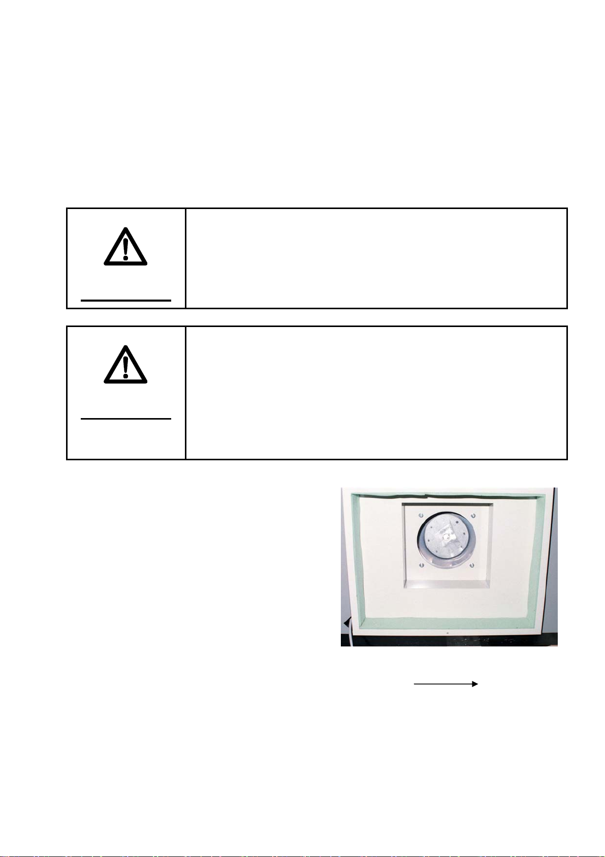
2. SET THE COVER FOR LEFT EDGE OF THE MACHINE.
that the pressure level should be 0.5MPa.
・
peration of the electro-magnetic
4. R
・ eep press stop button more than 2 seconds,
int as regulated turn.
5. O
・move the lapping paper covered on the dummy.
lar timber for fix the collar cramp.
・onnect the breaker for the factory.
e machine when you turn on the power switch of the machine.
Open the steam valve for supply the steam for the machine.
m leakage from the steam circuit.
According to the operating process later on, activate the machines function.
ss w/o shirt when you finish actual shirt.
3. RELEASE THE LOCK CONCERNING THE AIR.
・ Supply the air for the machine and make sure
Status of the body press iron is closed by
manual o
4KB310
valve for body press. For release the body
press iron, remove the manual switch of the
electro-magnetic valve for press from
condition of 「ON」to 「OFF」. Normally it
is available to work 「OFF」status.
ETURN TO THE ORIGIN POINT.
K
each device will move to the origin po
pen the dummy
Re
・ Remove rectangu
6. Connect the power supply
C
・ Check the indication on th
7. Steam Supply
・
・ Check the stea
8. TRIAL OPERATION OF THE MACHINE.
・
・It is necessary to activate 4 or 5 times trial pre
B-4

PERIODIC CHECK
DAILY PRE-USE CHECK
WARNING
Do not use the machine if all the safety devices and stop
buttons are does not work normally. Check this matters
everyday before use this machine.
Air filter for moisture and oil contents can automatically discharge such impurities with drain
when drains are accumulates. Check if impurities are discharged normally, and in case drains
are stagnant, and then please dispose of it by hand.
Check if all the pressure decompression valves are at specified pressures.
Main Regulator 0.50MPa
Tuck Slide Start 0.09Mpa
Tuck Slide Back 0.12Mpa
Dummy Slide Regulator 0.30Mpa
Remove the dust gathered on the inlet filter of the hot air blower for an arm.
Check if the cover of the dummy has not torn around the body and the tuck and if the pad has
not worn out if can not use please replace it as our genuine replace parts.
Check if air does not leak at the interconnected of the air hoses.
Check if steam does not leak at the interconnected of the steam as steam hose and/or each
plumbing parts.
Check if the air pressure is stable during operating the machine. If air pressure does not stay
appropriate level during the work check air filter and decompression valve.
PERIODIC CHECK AYEAR
Please execute periodically replace the filter elements as for following method.
NAME ELEMENTS REPLACEMENT TERM
Drain filter E-60D 2 years passes or pressure under 0.1MPa
Filter F4000-KIT 2 years passes or pressure under 0.1MPa
Oil mist separator MANTLE-ASSY 1 year passes or pressure under 0.1MPa
Please apply the grease for the dummy slide rail as well as apply the slide rail for tuck press
device for smooth movement.
Check if leakage from the packing of interconnected circuit of hot air blowing as for the
sleeves and air bag if you found any leakage, replace the packing for use long time.
C-1

NOTE
Efficiency of the filter for the air will be decrease by time passed
by so that the volume of the passes the air will be decreased
naturally. We are surely recommended to replace it as regulated
condition.
C-2

FUNCTIONS OF THE SECTIONS
START ST A RT ST OP
O N
OFF
CO U NT ER
PRO
AIR HEAT TUCK
TUCK OFF
P RE SS TI ME R
TIMING TIMER
13 7 71 9 10 11 12 5 8
2 3 4 6
OPERATION PANEL
①POWER SWITCH
When you turn the switch lever to “ON", that the Machine becomes ready to be operated. Times
you select are indicated in the timer display window.
②AIR (Timer for airbag start activate)
You can set the timing for air coming in the airbag (placed at the sides of the Dummy). This
timer counts at the time when trunk pressing starts, and when the set time passes by, hot air
comes in the sides of the Dummy.
REMARK:
-The longer set the time, the later timing for the hot air blowing comes.
→If the front placket curves, then set the time longer.
-The shorter set the time, the earlier timing for the hot air blowing comes.
→If wrinkles come out at the sides, then set the time shorter.
D-1

③HEAT (Timer for hot-air come)
You can set the timing for hot air comes into the sleeves. When you press cuffs setting button
that the timer starts counts and passes the previously sat the time hot-air blowing comes into
the sleeves.
REMARK:
-The longer set the time, the later timing for the hot air blowing comes.
→If the tuck spread becomes shorter, then set the time longer.
-The shorter set the time, the earlier timing for the hot air blowing comes.
→If you can see the wrinkles on the sleeve, then set the time shorter.
④TUCK (Timer for press the tuck)
You can set the timing for pressing the tucks. This timer starts concurrently with the HEAT
Timer.
REMARK:
-SET THE TIME LONGER, TIMING FOR PRESSING THE TUCKS BECOMES LATER.
→IF YOU CAN SEE THE WRINKLES ON THE SLEEVE, THEN SET THE TIME LONGER.
- SET THE TIME SHORTER, TIMING FOR PRESSING THE TUCKS EARLIER.
→ IF THE TUCKS OPEN AND BECAME SHORT, THEN SET THE TIME SHORTER.
⑤PRESS TIMER (Timer for press )
You can set 3 different pressing times from the Course 1 to 3. Choose any of them depending on
the material and moisture condition of a shirt.
⑥TUCK OFF (The Key)
When you press this button that the lamp turns on and the tuck pressing stops if you push it
once again, the lamp light turns off and the tuck press will start finishing works.
⑦START (Button)
After you have finished to setting the collar and vacuum, press these 2 buttons that the Dummy
moves to the right, making it ready for the trunk to be pressed and for the cuffs to be set. Keep
on pushing the buttons until the iron touches the Dummy.
⑧STOP (Button)
When you press this button return to the status of the press released condition and stops other
activations. If you would like to start again, keep on push this button more than 3 seconds.
Each of the devices will be returned to the origin point.
NOTE
In case if you could touch the safety device where located
tuck and truck trunk iron, activate the same function as press
the stop button.
D-2

➉to ⑪TIME ALTERATION BUTTON
Please refer “SET THE TIMER” paragraph.
⑫TIME INDICATION WINDOW
Indicate remaining time if you are in the finishing process, without this process will indicate
the setting time. If the timer became out of order it will be shown “ERROR MARK” in the
window.
⑬COUNTER WINDOW
Count the finished pieces.
HOW TO SET THE TIMER
1. SELECT THE COURSE
Push the timer button which you would like to change the
course and the lamp turns on that you have selected. Indicate
current setting time in the time indication window number 12
twelve.
1
2
3
2. PROGRAMMING MODE BUTTON
設定時間
PRO
Push this programming button number 9 nine approximately
1.5 seconds and time indication numbers turns into blinking
signal so that you can rewriting your favorable time.
3. SET THE TIME.
PRO
For an adjust your favor time push these marked ▲(Plus)
number ➉ten ▼(Minus) number ⑪eleven buttons. If you
would like to change the time widely keep press these button to
adjust your favorable time quickly.
4. ENTRY THE MEMORIZE
Push programming button number ⑨nine about 1.5
seconds again memorize the renewal time together with stop
blinking signal and the high tone P sound.
PRO
D-3

EXTERNAL FEATURES OF THE MACHINE
7
4
1
10
2
3
8
9
6 65 5
①CONTROL BOX
This contains electric control-related parts, such as sequencer and relay (thermal breaker).
②FOOT SWITCH
Pedaling this switch activates the collar fixer, where in turn operates vacuum.
③AIR FILTER
This serves as the inlet of hot air coming in the sleeves and forms a filter (net) collecting dust.
④AIR PRESSURE-REGULATING VALVE OF THE TUCK SLIDE
This regulates the expansion force of the sleeves.
⑤CUFFS CRAMP SWITCH
Push this button close the cuffs cramp and push it again it will be opened.
⑥START BUTTON (GREEN)
After sat both right and left cuffs press these two buttons enter the process of trunk finish work.
Keep the buttons on till the tuck press touches the shirt.
D-4

⑦STOP BUTTON (RED)
Push this button effects to return the status of released the press and stop the other function.
When you re-start to work the machine press this button more than three seconds each device
will be returned to the origin point.
⑧SAFETY GUARD
Safety guard device is installed where at in front of the tuck press iron and side of trunk iron if
this device start to work it is the same function of press the stop button. When you re-start to
work the machine keep stop button on more than three seconds then each device will be
returned to the origin point.
⑨OPERATEING PANEL
This panel has installed each setting and dummy movement button.
➉REGULATION BOX (ELECTRIC MOTOR CIRCUIT)
Installed magnet relay for the motor.
D-5

HOW TO OPERATE
FINISH PROCESS (Long Sleeves)
1. FASTEN THE SHIRT
Put the shirt to the dummy from left side back
around the dummy.
2. SET THE SHOULDER
Set the shirt to the dummy to make equal to the
seam line of the shirt.
3. SET THE COLLAR
Fix the collar by using the foot switch to make
equal space between collar and the collar block
then activates the vacuum when you press the
collar. When you release the collar press, step
on the foot press switch once again
E-1

4. SET THE BACK OF THE SHIRT
Pull down the bottom of the shirt lightly to not
appear any of slack wrinkles.
5. SET THE FRONT BOTTOM PART
Spread the bottom of a shirt for appropriate
condition to the dummy.
6. SET THE FRONT BOTTOM PART
Spread the bottom of a shirt for appropriate
condition to the dummy.
7. FRONT STAND
Set the front stand become straight from your
view. If you can find the curve on the shirt,
make it straight for fine finish. The angle for
the front stand both right or left makes narrow
as for the bigger shirt.
E-2

8. SMOOTH OUT OF SMALL WRINKLE
It may appear little wrinkle where the part of
pocket. shoulder, and the side so prior to finish
apply appropriate stroke or pull the shirt.
9. MOVE THE DUMMY
When you finished process number 8, press
START buttons at the same time by both hand
that the dummy will move to the right side.
*Keep the buttons on till the iron is completely
pressed.
10. TRUNK PRESS
The dummy was stopped at the extremely right
end and activates trunk press at the same time
and left arm comes to the front.
11. SET THE CUFF
Through the cuff on the pedestal for finish an
arm and the cuff place on the right position
without appear any wrinkles for the cuff and
tuck. Fixed the cuff by press the cuff cramp
switch. You can set the cuff either right or left
first.
E-3
Table of contents
Popular Finisher manuals by other brands

Ricoh
Ricoh DDP 92 user guide

Banner American
Banner American Finisher 4300 Operation manual

Fayat Group
Fayat Group DYNAPAC F1800W Operation & maintenance manual

Fayat
Fayat DYNAPAC F1800C Operation & maintenance manual

Dynapac
Dynapac DF 145 C operation & maintenance

Fayat
Fayat DYNAPAC F1000T T4f Operation & maintenance manual