ITW Mima G2503 Girotec RDL 1800 User manual

ServiceandInstallationManual
Machinepartsandelectricaldrawings
V3.2
G2503 Girotec RDL 1800
G0803 Girotec PL 2000/PLB 2000
G1004 Girotec ST 2000/STB 2000
G1204 Girotec ST 1800
G2904 Girotec ST3 2000
G1303 Girotec WT2 2000
G1503 Girotec WT3 2000

INSTALLATION
SEMI-AUTOMATICMACHINES
Selecting the
installation site
The installation site
will have to satisfy
the following
conditions:
ST and WT machines:
- Flat and level
surface
- Stable floor with
sufficient load-
carrying capacities
All machines:
- Dry
- Dust free
Indoor use only!!
Do not use in high
explosive area!!
Unpacking
1. Remove the plastic sheet packaging .
2. Open the transport box
3. Remove the screws on the transport
securing straps on the transport box.
4. Remove the transport securing straps
5. You can now remove the machine from
the box.
TIP:
You can use one wall of the transport box as
a ramp for RDL machine.
Setting up the
ST
1. Fasten the floor
plate of the ST with
suitable dowels.
2. After fastening a
cable to the
connection the
machine is raised
using a crane, fork
lift truck or a
suitable lifting
device, so that the
transport box can
be taken away
underneath it. Now
the machine can be
taken to the place
of use.
3. Set the tower on
the base plate as
shown in the
following
illustration
Fasten the tower
with the four
fastening bolts
V3.2

INSTALLATION
SEMI-AUTOMATICMACHINES
Setting up the
WT
1. Fasten the wall
mounting bracket
to appropriate
place.
2. After vertical
alignment of the
machine the floor
stand is fastened
using the
appropriate floor
anchors, taking
account of the
distance of the
wall bracket to
the wall. Then
fasten the wall
bracket with
suitable wall
anchors.
Connect the
power supply
ST and WT machines:
The machine is ready
to operate once the
plug has been placed
in a suitable 230 volt
supply outlet.
PL Machine:
Connect to the 24VDC
power supply
+ 24 VoltBrown
0 Volt Blue
RDL Machine:
Please charge
batteries for min.
12 hours before initial
operation.
V3.2

KEEP UP INSTRUCTION
SEMI-AUTOMATICMACHINES
V3.2
Weekly -Wipe off dust and dirt from the whole machine using dry cloth.
-Wipe off dust and dirt from the film distributor using dry cloth( especially from the photocell).
- Wipe off dust and dirt from the film distributor roller (1) using cloth with cleaning spray
Monthly -Wipe off dust and dirt from the guiding profile (3) using cloth with cleaning spray.
-Use silicon spray to lubricate the path (3) and sliding pieces (2).
-Check the brake plate has a minimum of 0,5mm of material.
-Lubricate the brake system bushing.
-Lubricate the lifting leverages and bushings.
-Lubricate the bushings of the hydraulic system.
1
2
3

KEEP UP INSTRUCTION
SEMI-AUTOMATICMACHINES
V3.2
Check that the brake plate has a minimum of 0,5 mm
material (a)
Functionality of film
brake system
a

KEEP UP INSTRUCTION
SEMI-AUTOMATICMACHINES
V3.2
1
2
Lubricate the brake system bushing.(1).
Be careful that lubricant does not reach the
surface between brake plate and brake roller (2)!!

Kundensienst- und Montageeinleitung
Maschinenteile und Strompläne
V3.2
G2503 Girotec RDL 1800
G0803 Girotec PL 2000/PLB 2000
G1004 Girotec ST 2000/STB 2000
G1204 Girotec ST 1800
G2904 Girotec ST3 2000
G1303 Girotec WT2 2000
G1503 Girotec WT3 2000

MONTAGE
V3.2
Auswahl des
Montageortes
Der Montageort soll
folgenden Bedingungen
entsprechen:
Für Maschinen Stund WT:
-Ebene und horizontale
Oberfläche.
-Robster Boden mit
ausreichend Tragfähigkeit
1.Der Platz soll trocken sein
2.Staubfrei
Nur in geschlossenen
Räumen verwenden!!
Nicht in Bereichen mit
erhöhter
Explosionsgefahr
betreiben!!
Auspacken
1. Die Verpackung aus Kunstoffbogen und
Festpappe entfernen.
2. Die Transportkiste öffnen.
3. Die Bänder für die Sicherung der
Maschine während des Transportes von der
Transportkiste lockern.
4. Die Sichrungsbänder entfernen.
5. Jetzt können Sie die Maschine aus der
Kiste holen.
NÜTZLICHER RAT:
Sie können eine der Wänder der Maschine
als Rampe für die Maschine RDL
verwenden.
Aufbau von ST
1.Die untere Platte
von ST 202 zum Boden
mit geeigneten
Stiftschrauben
befestigen.
2.Nachdem Sie ein Seil
an die
Verbindungsstelle
gebunden haben, soll
das System gehoben
werden, indem zu
diesem Zweck einen
Kran oder einen
Gabelstappler oder
anderes
Transportmittel
verwenden, sodass es
möglich wird, die
Transportkiste unter
dem System
rauszuholen. Jetzt
kann das System an
Ort und Stelle
abgeladen werden.
3.Legen Sie den Turm
auf die Grundplatte,
wie auf dem
Nebenbild gezeigt ist..
Der Turm durch
festziehen der vier
Verbindungsbolzen
befestigen.
HALBAUTOMATISCHEMASCHINEN

MONTAGE
HALBAUTOMATISCHEMASCHINEN
V3.2
Aufbau von WT
1. Die Konsole für
Wansmontage auf
einem geeigneten Ort
fixieren.
2. Nachdem die
vertikale Lage der
Maschine ausgerichtet
wird, wird der Grund
auf den Boden fixiert,
wobei zu diesem Zweck
geeignete Ankerbolzen
zu verwenden sind. Es
ist erforderlich, den
Abstand zwischen der
Wandkonsole und der
Wand zu beachten.
Danach die
Wandkonsole mit
geeigneten
Wandakerbolzen
befestigen.
Netzanschluss
Maschinen ST und WT:
Das System ist sofort
nach Anschluß an eine
geeignete Steckdose
mit Netzspannung 230
Volt betreibsbereit.
Maschine PL:
Anschliessen ans
Stromnetz mit Spannung
24 V Gleichstrom.
+ 24 Volz -> braun
0 Volt -> blau.
Maschine RDL:
Vor Inbetriebsetzen der
Maschine die Akku –
Batterien mindestens 12
Stunden laden..
Eingang 230 Volt Ausgangs
24V ST
TRANSFORMATOR
Gelb/Grün
Blau Braun Braun Blau
Gelb/Grün

WARTUNGSANWEISUNGEN
V3.2
Einmal in der Woche
Einmal im Monat
HALBAUTOMATISCHEMASCHINEN
- den Staub und die Verschmutzung von der ganzen Maschine mit einem trockenen Lappen entfernen.
- den Staub und die Verschmutzung von dem Folienverteiler und spezieller von der Photozelle mit einem trockenen Lappen
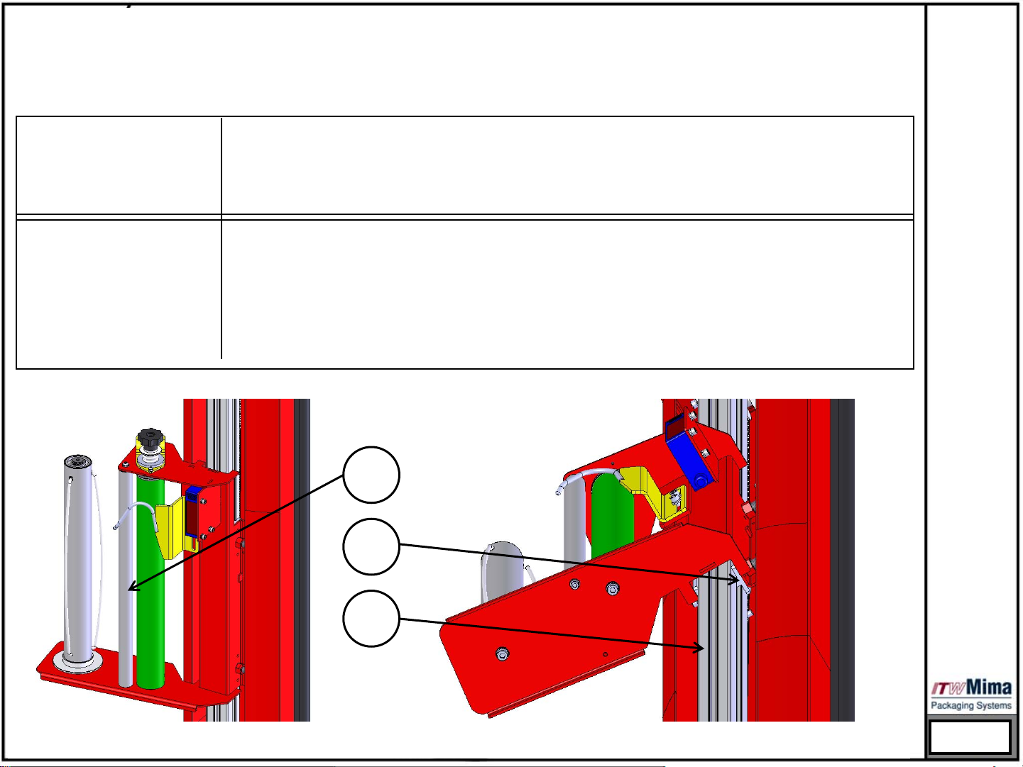
- den Staub und die Verschmutzung von den Verteilerrollen (1) des Folienverteilers mit Hilfe eines trockenen Lappens und
Reinigungsspray entfernen
- Den Staub und die Verschmutzung von den profilierten Richtungsband (3) mit Hilfe eines Lappens mit
Reinigungsspray entfernen,.
- Silikonspray zum Einfetten der Band (3) und der Gleitelemente (2) verwenden.
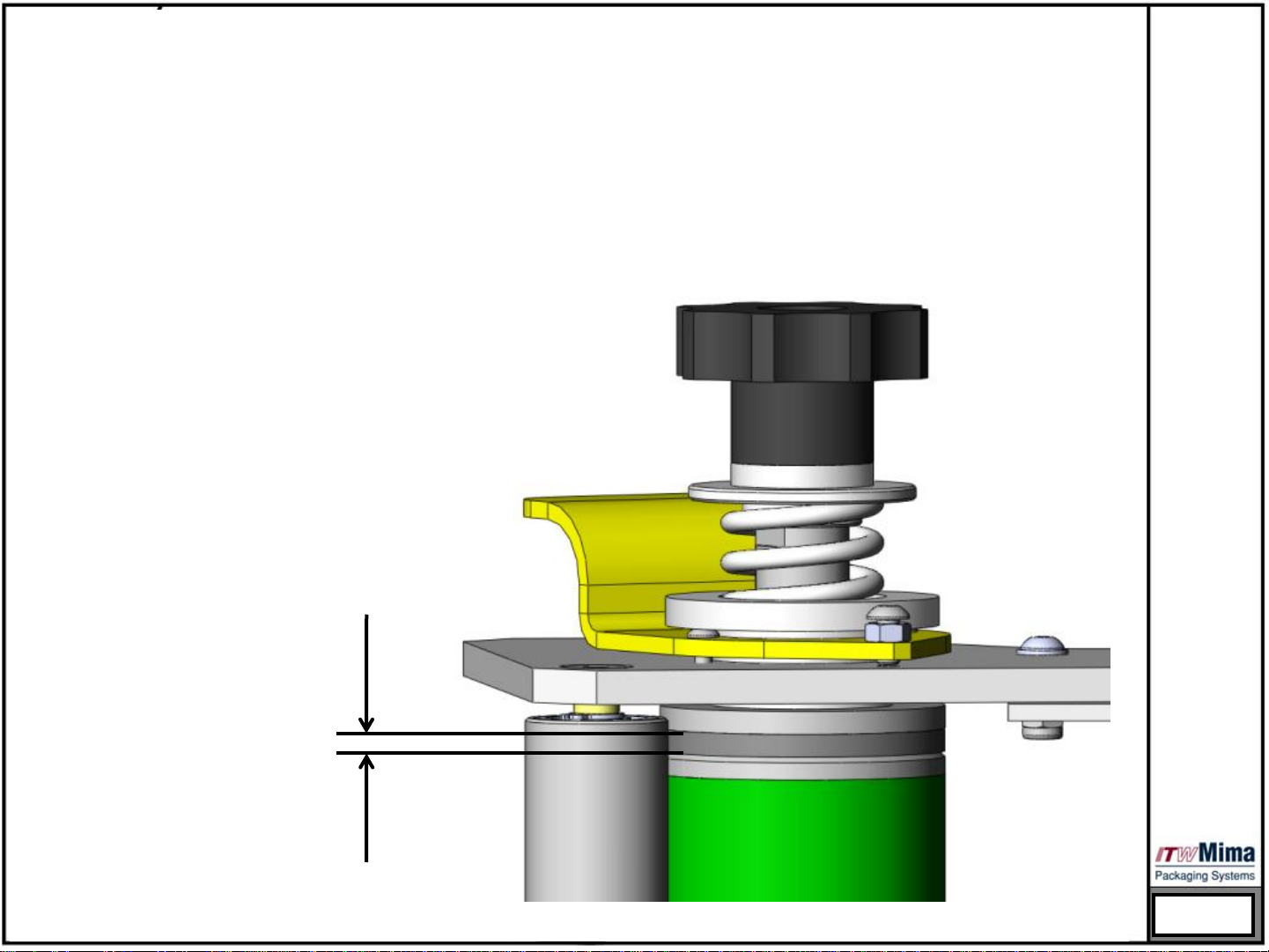
- Überprüfen, ob die Bremsplatte mindestens 0,5 mm Stoff hat.
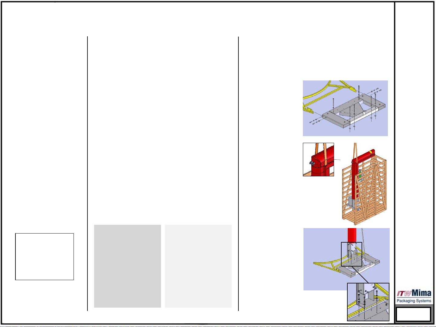
- Die Hülse des Bremssystems einfetten.
- Die Hubhebelmechanismen und die Hülsen einfetten.
- Die Hülsen des Hydraulischen Systems einfetten.
1
2
3

WARTUNGSANWEISUNG
V3.2
Überprüfen, ob die Bremsplatte mindestens 0,5 mm
Stoff (Stoffe) hat.
HALBAUTOMATISCHEMASCHINEN
a
Funktionalität des
Bremssystems für die
Folie.

WARTUNGSANWEISUNGEN
V3.2
HALBAUTOMATISCHEMASCHINEN
1
2
Die Hülse des Bremssystems einfetten (1).
Aufpassen, dass der Schmierstoff nicht die Oberfläche
zwischen der Bremsplatte und der Bremsrolle (2)
erreicht!!!

Manuel d’entretien et d’installation
Composants de la machine et schémas de
l’équipement électrique
V3.2
G2503 Girotec RDL 1800
G0803 Girotec PL 2000/PLB 2000
G1004 Girotec ST 2000/STB 2000
G1204 Girotec ST 1800
G2904 Girotec ST3 2000
G1303 Girotec WT2 2000
G1503 Girotec WT3 2000

INSTALLATION
MACHINESSEMI-AUTOMATIQUES
V3.2
Choix d’un palier
d’installation
Le palier d’installation doit
correspondre aux
exigences suivantes :
POUR DES MACHINES ST et
WT:
-surface plane et
horizontale.
-sol stable possédant une
capacité de charge
suffisante.
Pour toutes les machines:
-Le palier doit être sec.
-il ne doit pas y avoir de
poussière.
Exploitation uniquement
en lieu clos !!
Ne pas utiliser dans des
zones explosibles !!
Déballage
1.Enlevez l’emballage de feuilles en plastique et le
carton dur.
2.Ouvrez la caisse de transport.
3.Déserrez les vis sur les bandes de protection de la
machine durant le transport de la caisse de
transport.
4.Enlevez les bandes de protection de la machine
durant le transport.
5.Maintenant, vous pouvez déjà sortir la machine
de la caisse.
CONSEIL UTILE:
Vous pouvez utiliser une des parois de la caisse en
tant que rampe pour le transport de la machine
RDL.
Installation de la
machine ST
1.Fixez la plaque
inférieure de la
machine ST 202
contre le sol avec des
broches convenables.
2.Après avoir attaché
la corde à la place de
connexion, le système
doit être soulevé en
utilisant soit un
chariot-élévateur à
fourche, soit une
grue, soit un autre
appareil de levage,
afin qu’il soit possible
de retirer la caisse de
transport sous le
système. Maintenant
le système peut être
placé sur un endroit
destiné à
l’exploitation.
3.Posez la tour sur la
plaque générale,
comme cela est
indiqué sur
l’illustration suivante.
Fixez la tour en
serrant les quatre
boulons de
connexion.

INSTALLATION
V3.2
MACHINESSEMI-AUTOMATIQUES
Installation de la
machine WT
1.Fixez la console de
montage mural sur un
endroit convenable.
2.Après
l’établissement de la
position verticale du
système, on fixe la
base au sol en
utilisant pour cela des
boulons d’ancrage
convenables. Il faut
prendre compte de la
distance entre la
console murale et le
mur. Ensuite serrez la
console murale à
l’aide de boulons
d’ancrage mural
convenables.
entrée 230 Volt de sortie
24V ST
Transformateur
Vert/Jaune
Bleu Brun Brun Bleu
Vert/Jaune
Branchement à
l’alimentation
électrique
Machines ST et WT:
Le système est prêt à
fonctionner tout de
suite après que la fiche soit
branchée dans une
prise convenable à tension
de 230 volts
d’alimentation électrique.
Machines PL:
Branchez-la à une
alimentation électrique de
tension 24V de courant
continu.
+ 24 volts -> Brun
0 volt -> bleu.
Machines RDL:
Veuillez charger les
batteries chargeables
durant minimum 12
heures avant de mettre en
marche la machine.

CONSIGNES D’ENTRETIEN
V3.2
Une fois par semaine
Une fois par mois
MACHINESSEMI-AUTOMATIQUES
- Essuyez la poussière et les saletés de la machine entière en utilisant un chiffon sec.
- Essuyez la poussière et les saletés du chariot porte-bobine en utilisant un chiffon sec (particulièrement pour la
cellule photo-électrique).
- Essuyez la poussière et les saletés du rouleau pliant (1) du chariot porte-bobine en utilisant pour cela un chiffon
et un spray nettoyant.
- Essuyez la poussière et les saletés de la voie de guidage en profilé (3), en utilisant pour cela un chiffon et un
spray nettoyant.
- Utilisez un spray silicone pour graisser la voie (3) et les éléments glissants (2).
- Vérifiez si la plaque de frein possède au minimum 0,5 mm de matériel.
- Graissez la douille du système de frein.
- Graissez les mécanismes d’élévage à barres et les douilles.
- Graissez les douilles du système hydraulique.
1
2
3

V3.2
MACHINESSEMI-AUTOMATIQUES
CONSIGNES D’ENTRETIEN
Vérifiez si la plaque de frein possède au minimum 0,5
mm de matériel.
a
Fonctionnalité du système
de frein pour le film.

V3.2
MACHINESSEMI-AUTOMATIQUES
CONSIGNES D’ENTRETIEN
1
2
Graissez la douille du système de frein (1).
Faites attention afin que la graisse n’atteigne pas la
surface entre la plaque du frein et le rouleau de frein (2)!!

Instrucciones de servicio y montaje
Partes de la máquina y esquemas eléctricas
V3.2
G2503 Girotec RDL 1800
G0803 Girotec PL 2000/PLB 2000
G1004 Girotec ST 2000/STB 2000
G1204 Girotec ST 1800
G2904 Girotec ST3 2000
G1303 Girotec WT2 2000
G1503 Girotec WT3 2000

MONTAJE
MÁQUINAS SEMIAUTOMÁTICAS
V3.2
No utilize al aire libre!!No
utilize en zonas clasificadas
con riesgo de explosión!!
Selección de lugar de
montaje
El lugar de montaje debe
satisfacer las siguientes
exigencias:
Para máquinas ST y WT:
-Una superficie llana y
horizontal.
-Suelo estable con una
capacidad de carga
suficiente.
Para todas las máquinas:
1.Que sea seco el lugar de
montaje.
2.Que no haya polvo.
Desempaquetado
1. Quite el empaquetado de hojas plásticas y cartón
duro.
2. Abre la caja de madera para transportar la
máquina.
3. Afloje los tornillos en las cintas de protección de la
máquina durante el transporte de la caja para
transportar.
4. Quite las cintas que sirven para la protección de la
máquina durante el transporte.
5. Ya puede sacar la máquina de la caja de madera.
UN AVISO ÚTIL:
Puede usar uno de los costados de la caja de
madera para transportar como rampa para la
máquina RDL.
Construcción de
ST
1.Fije la placa inferior
del ST 202 al suelo a
través de unos
espárragos
oportunos.
2.Después de atar
una cuerda con el
lugar para conexión,
el sistema debe ser
levantado, utilizando
para tal fin una grúa,
montacargas de
horquilla u otra
instalación de
levantamiento
oportuna, para así
sacar la caja para
transporte de debajo
del sistema. Ahora el
sistema puede ser
colocada en el puesto
de uso.
3.Coloque la torre
sobre la placa
principal como ha
demostrado en la
siguiente ilustración.
Fije la torre
apretando los cuatro
pernos de conexión.
This manual suits for next models
8
Table of contents
Other ITW Mima Packaging Equipment manuals
Popular Packaging Equipment manuals by other brands

Sunbeam
Sunbeam FoodSaver VAC660 Instruction booklet

HP
HP Jet Fusion 5200 3D Series quick start guide

Orgapack
Orgapack CR 208 P Operating and safety instructions

Minipack-Torre
Minipack-Torre eco modular instruction manual

ENOTECNICA PILLAN
ENOTECNICA PILLAN CORKER-M instruction manual

Signode
Signode PRHR-34 Operation, parts and safety manual

Fromm
Fromm P328S quick start guide

Nonna
Nonna 42372 instruction manual

Minipack-Torre
Minipack-Torre Tunnel 50 Digit Installation, operation and maintenance

HSM
HSM Profi Pack 400 operating instructions

Minipack-Torre
Minipack-Torre Minimini instruction manual

Transpak
Transpak TP-6000 Technical Questions and Answers