ITW Simco-Ion IQ Power HL User manual

IQ Power™ HL 5201201 Rev. D
IQ Power™HL
Power Supply
INSTALLATION AND OPERATING INSTRUCTIONS

IQ Power™ HL 5201201 Rev. D
TABLE OF CONTENTS
1. SAFETY WARNINGS............................................................................ 3
2. DESCRIPTION ................................................................................... 4
4. SPECIFICATION ................................................................................. 5
5. INSTALLATION .................................................................................. 6
Mounting the Power Supply .................................................................................................6
Electrical Connections..........................................................................................................8
6. OPERATION .....................................................................................14
Power Supply Indicators .....................................................................................................14
Power Supply Operators .....................................................................................................14
Power Supply Number (Address) .......................................................................................15
Power Supply Number Table ..............................................................................................16
7. MAINTENANCE .................................................................................18
Cleaning the Static Bar.......................................................................................................18
8. TROUBLESHOOTING ..........................................................................19
9. ACCESSORIES AND PARTS...................................................................20
10. WARRANTY ...................................................................................21

1
IQPower™HL 5201201Rev.D
1. SAFETY WARNINGS
Simco-Ion recommends that these instructions be read completely before installation or
operation is attempted. Failure to do so could result in personal injury and/or damage to
the equipment.
NOTE – Statements identified with NOTE indicate precautions necessary to avoid
potential equipment failure.
CAUTION – Statements identified with CAUTION indicate potential safety
hazards.
NOTE – This equipment must be correctly installed and properly maintained.
Adhere to the following notes for safe installation and operation:
1. Read instruction manual before installing or operating equipment.
2. Only qualified service personnel are to perform installation and repairs.
3. All equipment must be properly grounded, including the machine frame to which the
equipment is mounted.
4. Disconnect input power to power supply before connecting or disconnecting static
neutralizing bars to the high voltage power supply.
5. Do not operate the power supply in close proximity to flammable liquids.
6. Do not use standard Ethernet cables with IQ Power
TM
Systems.
CAUTION – This product is intended to be supplied by a Listed AC Adapter
or Power Unit marked “Class 2” or “LPS” and rated output 24V
DC, 3.75A.
CAUTION – Electrical Shock Hazard
Disconnect input power to the power supply before connecting or
disconnecting static neutralizing bar or performing any maintenance to
the system. Avoid touching static neutralizing bar when power supply
is energized.
CAUTION – Fire Hazard
Do not install or operate the power supply in close proximity to any
flammable liquids or solvents.
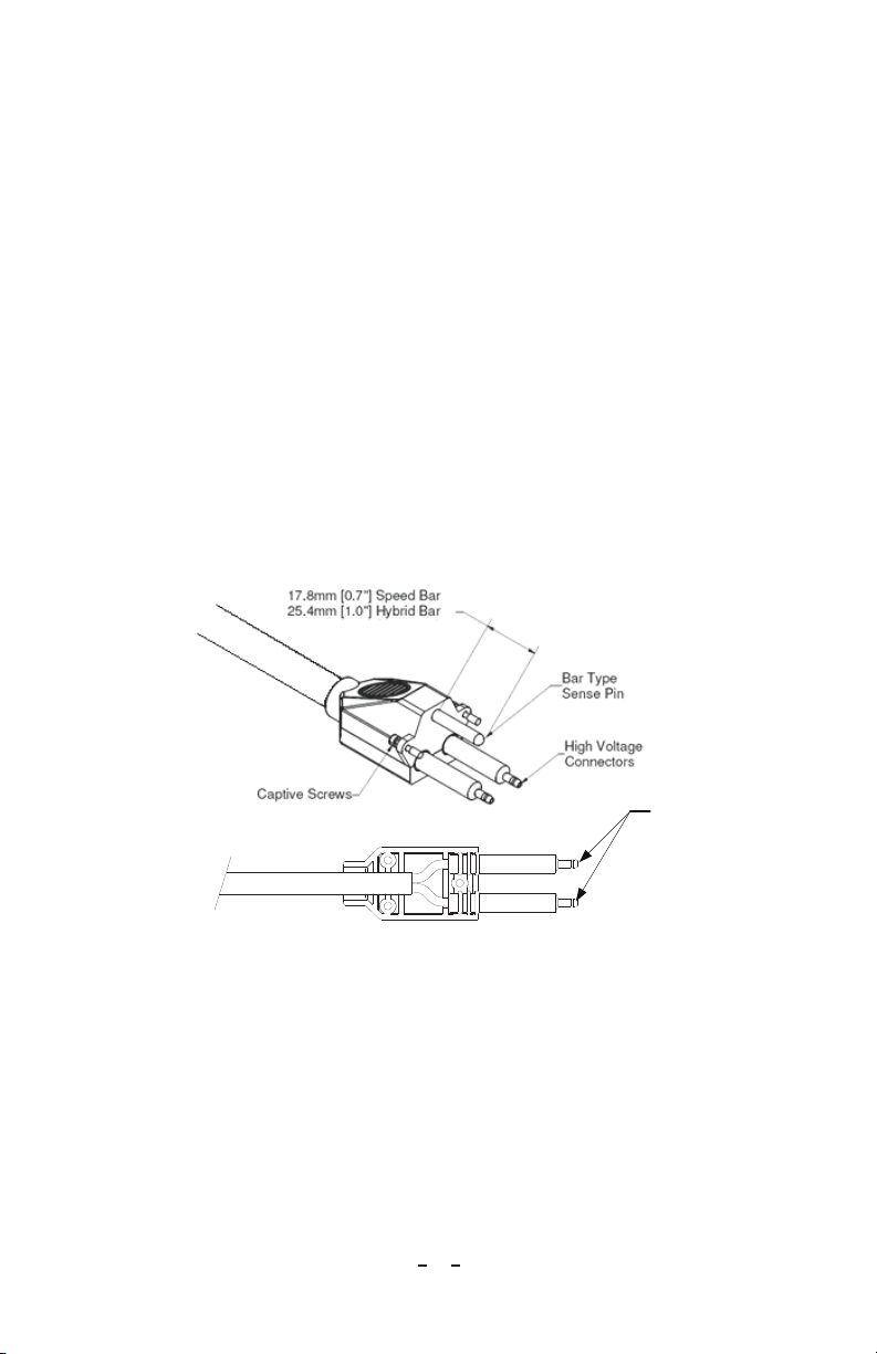
WARNING – Substitution of components may impair intrinsic safety. (refer
to Figure 1)
AVERTISSEMENT – La substitution de composants peut compromettre la
securite intrinseque. (referez-vous au schema 1)

2
IQPower™HL 5201201Rev.D
2. DESCRIPTION
IQ Power™ HL Power Supply: Associated Equipment for the IQ Power™ HL Static
Bar
Appareillage Connexe: For use in Non-Hazaradous (Unclassified) locations only
Simco-Ion’s IQ Power™ HL Power Supply provides microprocessor controlled high
voltage DC output to the static bar. The high voltage causes the ionizing pins on the static
bar to generate positive and negative ions. The electric field from the static charge on
the material being processed will attract opposite polarity ions from the static bar causing
the material to be neutralized. The excess ions will either recombine in air or dissipate
to ground.
The IQ Power™ HL Power Supply only supports operation of speed and hybrid type
static bars.
The IQ Power™ HL static bar is tailored to the application. Speed bars are optimized to
operate on high speed webs at distances of 50 to 230 millimeters [2 to 9 inches]. Hybrid
bars operate at distances of 150 to 460 millimeters [6 to 18 inches] on webs where the web
path is somewhat variable.
The IQ Power™ HL static bar has a plug-in style high voltage connector for fast and easy
installation. The connector features a pin that “tells” the IQ Power™ HL Power Supply
what type IQ Power™ HL bar is installed and optimizes the power supply output for that
type of bar.
Features
• Single momentary push-button calibration simplifies set-up.
• Bar graph display indicates ionizing performance of system.
• Indicators display status of neutralizing system, power, service required and
detection of system faults.
• Relay contact output “echoes” indicators for remote sensing and alarm.

3
IQPower™HL 5201201Rev.D
4. SPECIFICATION
IQ Power™ HL Power Supply
Input Power 24V DC, 1.5A from AC adapter
Output Voltage +/-7 kV “Speed Bar”; +/-8 kV “Hybrid Bar”
Operating Temp 43°C [110°F] max
Dimensions 202L x 123W x 106H mm [7.95”L x 4.85”W x 4.17”H]
Weight 1.94 kg [4.28 lb]
Enclosure Aluminum, blue polyester powder coated
High Voltage Connectors 2 proprietary IQ Power™ HL plug-in outlets
AC Adapter
Type “Universal” desktop
Input Power 100–240V AC 50/60Hz input (IEC 320 inlet)
Output 24V DC, 3.75A max
Dimensions 132L x 60W x 34H [5.19”L x 2.36”W x 1.34”H]
Weight 0.45 kg [1.0 lb]
Enclosure Thermoplastic, black

4
IQPower™HL 5201201Rev.D
5. INSTALLATION
Mounting the Power Supply
Figure 1a. IQ Power™ HL Control Drawing

5
IQPower™HL 5201201Rev.D
Figure 1a. IQ Power™ HL Control Drawing
A. Locate at a convenient place within reach of the static bar high voltage cable. Power
for the AC adapter and an electrical ground connection must be available.
B. Secure to the mounting surface (commonly a machine frame) using M5 or M4 [#10
or #8] hardware (not supplied).
NOTE - Do not apply line voltage to the AC adapter until installation is complete.
Also ensure that all input power switches are in the OFF (0) position.
CAUTION - Do not install the power supply within hazardous (classified) locations.
Install in non-hazardous (unclassified) locations only (refer to Figure 1a).

6
IQPower™HL 5201201Rev.D
Electrical Connections
A. Ground power supply by connecting a ground lead between the ground terminal on
the flange of the power supply and a good electrical machine ground.
B. Connect static bar by cutting the high voltage cable to length, terminating the leads,
and connecting to the power supply: (Refer to Figure 5.2)
1. Cut HV cable to length, leaving an extra 3¼” for the connector.
2. Strip black plastic jacket back 2½”, being careful not to nick the insulation of the
HV wires.
3. Strip insulation of HV wires back ¾”, being careful not to nick the conductor of
the HV wire.
4. Straighten conductors and insert into HV connector until conductor protrudes out
from the tip of the connector.
5. Solder conductor to tip of connector by applying solder to exposed conductor.
Ensure that that solder does not overflow and fill neck area of tip.
6. Trim off excess conductor protruding from tip of connector.
Solder
& Trim
Figure 2. High Voltage Cable Terminations
7. Place HV Connectors into the HV plug bottom. The black plastic jacket should
be fully engaged in the strain relief section of the HV plug. Flex conduit (where
used) should be fully engaged in the hub section of the HV plug.
8. Install the HV plug top onto bottom making sure the plug comes together
properly with no binding or gapping. Hold together firmly.
9. Insert nylon screws through holes in plug bottom and tighten to secure plug
together (do not over tighten screws).

7
IQPower™HL 5201201Rev.D
10. Then plug in high voltage connector on static bar to HV1 or HV2 on power
supply. Secure high voltage connector with the (2) captive screws on the sides
of the connector. Do not over-tighten.
CAUTION – Shock Hazard
Do not connect static neutralizing bar with power supply energized. Disconnect
input power or switch power off before connecting static bar.
NOTE – Failure to fully seat the high voltage connectors into the power supply
connectors may result in permanent damage to the bar, cable or power supply.
C. Connect power supply alarm output (if used). The power supply “Alarm Output”
is a standard DB25 pin connector located on the end of the IQ Power™ HL Power
Supply. A maximum distance of 3 meters [10 feet] or less is recommended.
Pin Description Pin Description
1Remote on/off optocoupler (-) 10 No connection
14 Remote on/off optocoupler (+) 6No connection
19 No connection
2Clean Bar Relay (common)* 11 Power Relay (common)*
3 Clean Bar Relay (norm close)* 7 Power Relay (normal closed)*
16 Clean Bar Relay (norm open)* 20 Power Relay (normally open)*
8Fault Relay (common)*
4Fault Relay (normally closed)* 12 Power in (ground)**
17 Fault Relay (normally open)* 24 Power in (ground)**
9Bar On Relay (common)* 13 Power in (+24V DC)**
5Bar On Relay (normal closed)* 25 Power in (+)**
18 Bar On Relay (normally open)*
*30V 1A Rating on Contacts
**1.6A Rating, Connect pins 12 & 24 in parallel and 13 & 25 in parallel

8
IQPower™HL 5201201Rev.D
24VD
C
Figure 3. Alarm Output Connections
The power supply alarm output provides a variety of relay contact outputs that echo
the status of the power supply indicator lights. The relay contacts are rated for a
maximum of 1A at 30V DC. The alarm output connector also provides a means
of remote power in. (Refer to Figure 3)
D. Remote On/Off Control (if used). The power supply “Alarm Output” connector
also provides for remote on/off control of the power supply. Remote on/off control
is configured with a jumper on a pin header on the main power supply circuit board.
The default configuration is with the remote control disabled. The remote control
can be configured “normally off” or “normally on” by the jumper setting (refer to
Figure 4). To access the jumper the cover will have to be removed from the power
supply. Disconnect all input power from the power supply then remove the six
screws securing the cover and slowly and carefully remove the cover.
Remote On/Off
Disabled
Normally Off
Opto High = Unit ON
Opto Low = Unit OFF
Normally On
Opto High = Unit OF
F
Opto Low = Unit ON
Main PC Board
Figure 4 Jumper Position at J3 for Remote Control Operation

9
IQPower™HL 5201201Rev.D
NOTE – DO NOT USE standard Ethernet cables with IQ Power systems. Avoid
permanent equipment damage by using only Simco-Ion modular cables. (Refer to
Section 9 , Accessories and Parts).
TOP VIEW
SIDE VIEW
6
5
4
2
3
1
WIRING DIAGRAM
8
7
6
5
4
2
3
1
8
7
1
1
Figure 5a. IQ Power Crossover Modular Cable
6
5
4
2
3
1
WIRING DIAGRAM
8
7
6
5
4
2
3
1
8
7
TOP VIEW
SIDE VIEW
1
1
Figure 5b. IQ Power Straight through Modular Cable

10
IQPower™HL 5201201Rev.D
There is a ribbon cable connecting the face label on the cover to the main circuit
board. Use care not to disconnect this cable. If the cable becomes disconnected, lift
the latches on the sides of the ribbon cable connector, insert the ribbon cable fully
into the connector and press the latches back down.
Reposition the jumper to enable the remote control either “normally on” or “normally
off”, as desired (refer to Figure 4). Then replace the cover and secure with the six
screws.
When operating a power supply using the remote control circuit, power may be
applied through the “Alarm Output” connector or the “Power In” connector on the
end panel. If the “Power In” connector on the end panel is used, the “Power” switch
must be set to the ON (1) position.
Remote control is established by applying 24V DC to the “Alarm Output”
connector pins as specified in Figure 3. The user-applied 24V DC drives a low
current optoisolator on the IQ Power™ HL Power Supply main circuit board, turning
the power supply on or off, depending on the configuration of jumper J3.
E. Connect other power supplies (if used). IQ Power™ HL Power Supplies can be
connected together via a “data buss”. The data buss allows one IQ Power™ HL
Communication Module to serve multiple IQ Power™ HL Power Supplies and feed
the data from all power supplies into the network. A total of 10 power supplies may
be chained together on one data buss. Cables for the data buss must be 8-conductor
modular cables with RJ-45 connectors wired “straight through” (reference color:
white, Figure 5a and 5b).
If multiple IQ Power BPS power supplies are connected together, each power
supply must be given a unique address. This is necessary to enable reliable digital
communication. The power supplies should each be given a unique address prior
to connection with the “data buss” (the chaining together of power supplies). See
section 6.3 Power Supply Number (address) for details on re-addressing the power
supplies.
The modular cable plugs into either “PS COMM 1” connector on a power supply
and chains to the next power supply where it again plugs into either “PS COMM 1”
connector.
F. Connect AC Adapter (make sure “POWER” switch on power supply is in the “OFF”
(0) position). Route low voltage wire clear of moving machine parts and protect it
from abrasion. Secure using nylon wire ties (not supplied). Do not over tighten.
Insert barrel connector into “POWER IN” connector on the power supply. Hand
tighten barrel connector nut to secure.
Connect line voltage to input side of AC adapter. The AC adapter is a universal input
type that accepts line voltage from 100 to 240 V AC 50/60Hz. The AC adapter
line voltage connector accepts a line cord with an IEC 320 connector (supplied). The

11
IQPower™HL 5201201Rev.D
line cord also provides electrical ground to the AC adapter. Check electrical ground
integrity in the line voltage receptacle used for the AC adapter. This ground must not
be defeated.
G. Connect user supplied power (if used). In cases where the user does not want to
use the AC adapter but wants to supply 24V DC power to the IQ Power™ HL
Power Supply, user supplied 24V DC power may be applied two ways.
The “Power In” connector on the end panel of the IQ Power™ HL Power Supply
may be used to supply power to the system. This connector requires the use of a
Switchcraft 760K barrel type power plug. The plug should be wired +24V DC
to center and common (ground) to outer barrel. The common must be bonded to
electrical ground. Wired in this fashion, the “Power” switch on the end panel of the
power supply is in circuit.
Alternatively, the “Alarm Output” connector on the end panel of the IQ Power™ HL
Power Supply may be used to supply power to the system. This connector requires
the use of a standard DB25 connector. The connector should be wired:
• +24V DC to pins 13 & 25
• Common(ground)topins12&24
To ensure current carrying capacity, two pins are used for each connection. The
common must be bonded to ground. Wired in this fashion, the “Power” switch on the
end panel of the power supply is bypassed. (refer to Figure 3)
Power supplied in the above fashion must have adequate current available to power
all components on the system (maximum 4A). Input power should be appropriately
fused for safety purposes.

12
IQPower™HL 5201201Rev.D
6. OPERATION
NOTE – Before switching on power supply; ensure that units are properly
grounded and that static bar & probes are properly installed.
Power Supply Indicators
Power: Lights (green) to indicate power is on and the IQ Power™ HL Power Supply is
ready to operate.
Comm: Lights (green) to indicate digital communication is established with an IQ
Power™ Communication Module or Control Station. The Comm light will flicker to
indicate communication activity.
Bar On: Lights (green) to indicate when the static neutralizing bar is active.
Fault: Lights (red) to indicate faulty condition of static bar, power supply or high voltage
connections. Power will have to be turned off to clear the fault. When fault is cleared and
power is restored, the fault light will be extinguished.
Clean Bar: Lights (yellow) to indicate need to clean static bar. Clean Bar indicator may
light with low ion output (dirt build-up on ion emitters) or high output current (conductive
contamination on face of bar).
Mode: The indicator next to the type of bar connected will light (green). “Speed” or
“Hybrid” will be indicated. In cases where two different types of bars are connected,
the system will set for the safer of the two operating voltages and light the corresponding
Mode indicator.
The Output indicators (along with the Mode indicators) also indicate the power supply
number during start-up of the power supply.
Output: The output indicators range from “Low” to “High” in 10 steps
(2-red, 3-yellow, 5-green) and light to indicate the system relative ion output. The output
will normally be in the high range. Low output generally indicates the need to clean the
static bar.
Power Supply Operators
Calibrate: Is a momentary push button switch located on the face label. Pressing the face
label firmly on “Calibrate” initiates the calibration sequence and sets the relative nominal
ion output for the system.
The Calibrate button is also used to change the power supply number. This number
is used in software to identify the power supply in systems that contain multiple power
supplies and include an optional Communication Module.

13
IQPower™HL 5201201Rev.D
System Start-up:
A. Apply line voltage to the AC adapter.
B. Move the power supply “Power” switch to the “On” (1) position.
C. The power supply indicators will briefly self-test during which all will light.
D. Immediately after the self-test, the power supply number (default: 01) will be briefly
displayed. (see Power Supply Number)
E. After the power supply number displays, the power supply indicators will settle to
display the system status.
On new systems the output indicator will settle to display low output, initial
calibration must be performed.
NOTE – Calibration should be performed when the system is first installed and
may be performed after the static bar has been cleaned and the system verified as
operating correctly.
F. If the system is new, perform an initial calibration. The initial calibration sets the
relative nominal ion output for the system. The calibration should only be performed
on IQ Power™ HL systems that are new or just cleaned and known to be in proper
working order.
During calibration the target to be neutralized (web, film, etc.) may remain in place,
but MUST NOT BE MOVING. If the web is moving past the static bar (e.g. the
machine is in operation) the calibration may be faulty.
The system should be “on” and in the operating mode (not in start-up self-test or
power supply number display modes). Press the face label on the power supply
firmly on the word “Calibrate”. This will initiate the calibration sequence and set the
relative nominal ion output for the system.
During calibration the system output will be cycled and the three mode lights will
illuminate. At completion of the calibration the speed and distance lights will flicker. The
indicated ion output will be high. The calibration sequence takes less than one minute.
The calibration data is stored in non-volatile memory and used on subsequent power
ups.
Power Supply Number (Address)
Each IQ Power™ HL PS has two numbers associated with it. These numbers serve to
identify the power supply in digital communications. One number is the IQ Power™ /
Performax IQ HL PS address, which can be a number of 1 through 10 (the default is “1”).
The other number is the IQ Power™ Station number, which can be a number of 1 through
30 (the default is “30”).
When the IQ Power™ HL PS is first turned on it will illuminate all LED indicators as
a self test. Then it will briefly display first the IQ Power™ / Performax IQ address in
steadily lit indicators and then it will display the Ion Power station number in flashing
indicators. See the following table for interpreting the address numbers.

14
IQPower™HL 5201201Rev.D
Power Supply Number Table
IQ Power/
Performax IQ HL
PS Address
Ion Power
Station
Number
OUTPUT LED
Illuminated
SPEED MODE
LED
HYBRID MODE
LED
DISTANCE
MODE LED
1 (default) 1LOW (1) - - -
2 2 2 - - -
3 3 3 - - -
4 4 4 - - -
5 5 5 - - -
6 6 6 - - -
7 7 7 - - -
8 8 8 - - -
9 9 9 - - -
10 10 (none) On - -
1 11 LOW (1) On - -
2 12 2 On - -
3 13 3 On - -
4 14 4 On - -
5 15 5 On - -
6 16 6 On - -
7 17 7 On - -
8 18 8 On - -
9 19 9 On - -
10 20 (none) On On -
1 21 LOW (1) On On -
2 22 2 On On -
3 23 3 On On -
4 24 4 On On -
5 25 5 On On -
6 26 6 On On -
7 27 7 On On -
8 28 8 On On -
9 29 9 On On -
130 (default) (none) On On On
Adjusting the power supply number is only necessary in systems with multiple power
supplies daisy chained to a Communication Module or monitoring device. Having
multiple power supplies with the same numbers connected to a Communication Module
or monitoring device is not permitted.

15
IQPower™HL 5201201Rev.D
To adjust the power supply number, turn the unit on and wait for the LED self-test to
complete. The COMM light will briefly stay lit and the power supply number may
be adjusted at this time. Press and hold the Initial Calibration button until the power
supply number increments by one (5 second window). Subsequent presses of the Initial
Calibration button will increment the power supply numbers (5 second window). The
Ion Power station number will be displayed and the IQ Power™ / Performax IQ HL PS
address will “map” as shown on the Power Supply Number Table. The incrementing
“wraps around”. Stop pressing the Initial Calibration button when the desired power
supply numbers have been reached. Wait 5 seconds, the COMM light will go out and the
Speed and Distance LEDs will flicker, indicating the power supply numbers have been
saved.
To reset the unit to its factory default power supply numbers (see Power Supply Number
Table), press and hold the Initial Calibration button while turning the unit on. Continue
holding down the Initial Calibration button while the Output indicators “count-up” and
when the COMM light starts flashing, then release the Initial Calibration button. When
just the Speed and Distance LED flicker, the default power supply numbers (address = ”1”,
station number = ”30”) are saved.

16
IQPower™HL 5201201Rev.D
7. MAINTENANCE
NOTE – Only qualified service personnel are to perform maintenance tasks.
CAUTION – Electrical Shock Hazard
Turn off power supply before cleaning bar or performing any maintenance on
the system.
The accumulation of contamination on the ionization emitter points and static bar
surfaces will reduce neutralizing efficiency of the bar, therefore it is recommended that
maintenance of the system be performed when the Clean Bar indicator on the display
module illuminates or every three weeks, whichever comes first. Dirty environments may
require more frequent cleaning. Maintenance should be performed by qualified service
personnel only.
Cleaning the Static Bar
A clean brush with nylon bristles should be used to keep the ionization emitter points of
the static bar clean. Periodic use of the brush will prevent deposits from accumulating on
the points. The emitter points must remain sharp for optimum operation.
NOTE –Do not scrape points with any hard or sharp object that may damage points.
A. Turn off power supply.
B. Remove dirt particles deposited on the static bar with a dry, stiff nylon bristle brush.
C. Blow off the static bar with clean, dry compressed air.
D. Remove resistant coatings deposited on static bar by wiping with isopropyl alcohol
or mineral spirits applied to a clean cloth. Apply isopropyl alcohol or mineral spirits
to a stiff nylon bristle brush and thoroughly scrub the ionization emitter channels of
the bar.
E. Blow static bar dry with clean, dry compressed air and ensure the bar is completely
dry before re-applying power to the bar.
NOTE – Do not soak static bar or related components in alcohol or mineral spirits.
Do not use harsh solvents such as lacquer thinner, naphtha or acetone.

17
IQPower™HL 5201201Rev.D
8. TROUBLESHOOTING
PROBLEM CAUSE SOLUTION
Power indicator
NOT illuminated.
Power not on at power
supply.
Turn on Power switch on end
of power supply case.
Poor electrical connections.
Check input power
connections, both 24V
DC and line voltage.
Defective AC adapter. Replace AC adapter.
Clean Bar indicator
illuminated.
Process material fouling
static bar ion emitters.
Remove process material
from static bar.
Dirt build-up on ion emitters
or conductive contamination
on face of bar.
Clean ion emitters and static
bar. See Maintenance section
for details.
Bar ON indicator
NOT illuminated.
No static bar connected. Install static bar and connect
to power supply.
Static bar high voltage
connector is not connected.
Turn off power, reconnect
static bar and secure plug
with captive screws.
Static bar high voltage
connector missing bar type
sense pin.
Replace static bar high
voltage connector plug.
Fault indicator
illuminated.
Static bar mounted too close
to grounded metal.
Separate static bar from
grounded metal.
Damage to high voltage
connector.
Replace high voltage
connector.
Damage to high voltage
cable. Replace static bar.
High voltage module inside
power supply faulty Replace high voltage module.

18
IQPower™HL 5201201Rev.D
9. ACCESSORIES AND PARTS
IQ Power™ HL Power Supply: Part Number
(no AC adapter) 4012508
(With AC adapter, 100/120V AC Jap/ N.Amer. Cord) 4012509
(With AC adapter, 230V AC N.Amer. Cord) 4012510
AC Adapter (100-240V AC input, standard, 1.6A) 4108104
AC Adapter (100-240V AC input, large, 3.75A) 4108774
Line Cord, 100/120V AC Japan/ N. Amer. 4106272
Line Cord, North American 230V AC 4106274
Modular Cable (IQ Power 8-conductor, straight through wired, RJ-45)
for use between multiple IQ Power™ HL Power Supplies:
DO NOT USE Standard Ethernet Cables (Figure 5a and 5b)
(0.91 meter [3 foot] white) 4520788
(2.13 meter [7 foot] white) 4520789
(4.27 meter [14 foot] white) 4520791
(7.62 meter [25 foot] white) 4520792
HL Junction Block 4012352
HL Conduit Seal 4108231
Table of contents
Other ITW Power Supply manuals

ITW
ITW Orbitalum ORBIMAT 165 CA User manual

ITW
ITW Simco-Ion Dual Phase+ User manual

ITW
ITW Simco-Ion Chargemaster Pinner Superbar User manual

ITW
ITW Simco-ion IQ Power MPS User manual

ITW
ITW SIMCO ION IQ Power BPS-C User manual

ITW
ITW Simco-Ion D167Q User manual

ITW
ITW Simco-Ion Chargemaster VCM30 Series User manual

ITW
ITW Simco-Ion S165S User manual

ITW
ITW SIMCO ION D Series User manual