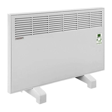
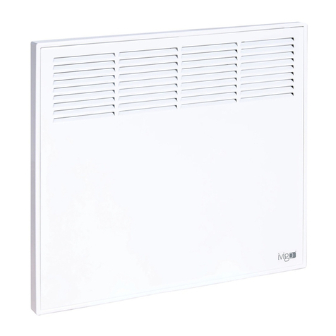
IVIGO EPK4550P05 User manual

EN USER MANUAL
PROFESSIONAL
CONVECTOR HEATER
since
Models::
Professional
EPK4550P05
EPK4550P07
EPK4570P10
EPK4570P15
EPK4590P20
EPK4590P25

ivigo.com
Instant Heat With Fan Forced
ELECTRIC HEATER WITH FAN

LANGUAGES
EN USER MANUAL.................................................................... 01
DE MONTAGE UND BETRIEBSANLEITUNG.................................. 25
TR MONTAJVE KULLANMA KILAVUZU ..................................... 49
HU HASZNÁLATI ÚTMUTATÓ..................................................... 73
RO MANUALUL UTILIZATORULUI............................................... 97
www.ivigo.com
DO NOT COVER
3
YEAR
GUARANTEE

4
QUICK START GUIDE
PtyP: Program Settings (daily/weekly)
d_Pr (daily)
h_Pr (weekly)
tSEt: Setting Time and Day
hSEt: Weekly Program Setting
p_01
p_02
..........
p_12
ASEt: Adaptive Start Parameters
P 01 (early turn-on time per degree)
P 02 (maximum early turn-on time)
oPEn: Heat Loss Detection Parameters (Windows, doors, etc. left open)
P 01 (standby time)
P 02 (sensing temperature)
AnFr: Anti-Frost Setting
o
on
uEr: Software Version Monitoring
CodE: Key Code (introduction of Exclusive Keylocker)
CCod: Erasing the Key Code
CntC: Temperature Calibration
CLdr: Display Brightness Adjustment
Resetting the settings (daily mode): Press and hold the upper two buttons ( )and ( )
simultaneously for ten seconds until you see “CLr” on the screen. Then the device goes to factory
settings.
Accessing settings: In order to access to the settings menu, use the On/O switch ( ) on the side
to turn o the device. Press and hold the power button ( ) while switching on the unit from the
side. To turn o the device, please use the On/O switch ( )on the side. To switch on, press and
hold the power button ( ). The device display shows the rst option available in the menu. You
can switch between the options with the ( ) and ( ) buttons. To see and edit the details of an
option that appears on the screen, press and hold the power button ( ) for 3 seconds. To save
the changes, press and hold the power button ( ) for 3 seconds. To exit without saving, turn o
and back on the device via the on/o switch ( ) on the side.
Professional Model

5
EN
Ivigo is a registered brand of Mastaş Company.
IMPORTANT NOTE:
The device is calibrated by the manufacturer. But due to
the nature of temperature sensing the measured temperature may vary
by the facts such the ground clearance distance, window or door distances,
the size of the room or by the heat circulation streams inside the room.
Digital display brightness decreases automatically at night
.
ENVIRONMENTAL POLICY
We hereby commt that we are gong to:
and recyclng thereof whenever possble, dspose unused wastes
through the most approprate methods,
ther envronmental performance,
awareness tranngs
Produced n accordance wth,
EN 60335-2-30: 2011 A11: 2012 standarts.

6
Our Esteemed Customer,
Please comply with the following instructions in order to receive product
services completely:
1. Have the certicate of warranty stamped by the seller while purchasing
the product.
warranty stamped by our nearest authorized seller.
all the instructions in this manual completely before using this unit and
keep it as a reference source in order to use this product, in the most
ecient way, which is produced in our modern facilities in accordance
your product.
5. If the unit does not operate in rst start or is out of order please ask for
help from Distributor’s Consumer Advisory hotline.
6. The product has a service life of 10 years when used according to
specications.
Professional Panel Convector Heater Model Selection
Model Recommended
Heater Power
(watt)
Room Area
(m2)
EPK 4550 P05 500-600 3 - 6
EPK 4550 P07 700 -850 4 - 9
EPK 4570 P10 1000-1200 6 - 12
EPK 4570 P15 1400-1600 9-17
EPK 4590 P20 2000-2400 12 - 24
EPK 4590 P25 2300-2700 14-28
The heat requirement
depends on factors such as
the exterior temperature,
room heat isolation,
door open/cl ose cycles.
The values stated on the
left table are for average
conditions with an outside
temperature of 8 - 10
degrees therefore when
calculating the heater
power these factors should
betakenintoconsideration.

7
EN
SAFETY INSTRUCTIONS
convector only with the Alternative Voltage (AC) and sucient current rated power
outlets.
will not be deemed responsible for the damages caused due to use without the
application of grounding.
instructions carefully.
Advisory Hotline in case a breakdown or damage. Never mount or use your heater.
Please refer to the dealer with warranty card and bill.
use for long periods and before cleaning.
carriage, assembly and use.
intended use for. Do not place cloth thereon.
or stored.
could create an electric shock hazard.
tension possibilities. Do not unplug by pulling on cord.
operating any switch on the product or touching the plug.

8
physical, sensory or mental capabilities, or lack of experience and knowledge, unless
they have been given supervision or instruction concerning use of the appliance by
a person responsible for their safety.
cables, timers or programmers.
this may cause an electric shock or re damage to the appliance.
Keep combustible materials at least 1.0 m away from the heater.
power outlet.(receptacle)
surface. Always switch o and let cool down before moving.
legislation.
a year regularly.
convector heater with walls, curtains etc. Keep at least 0.5 m away from the heater.
change the network cable of your electric panel convector heater. Do not operate
your heater.

9
EN
TABLE OF CONTENTS
1. GENERAL OVERVIEW AND TECHNICAL FEATURES 10
2. INSTALLATION INSTRUCTIONS 12
3. OPERATING INSTRUCTIONS 15
4. CLEANUP and MAINTENANCE 22
5. TRANSPORTATION INFO 23
6. PRACTICAL AND USEFUL INFORMATIONS 23
7. GUARANTEE CONDITION 23
Ivigo has adopted producing healthy, comfortable, durable and energy-
ecient heating systems as a principle and has always become a pioneer

10
Professional Panel Convector
Ivigo Professional Panel Convector
heater’s body and front panel have
been produced by the employment
resistance heater with aluminum
convectors placed in the unit
provides heating by virtue of the
grids thereon. Cold air entering
through the channels on the lower
skirt of the body exits as warm air
through the grids on the front panel
following its course through the
electric resistance. Air circulated in
this way provides heating by virtue
of natural circulation.
The display automatically dims or
brightens, adjusting to the level of
light in the room. The automatic
mode is on by default. The display
light is adjustable via the settings
menu, a convenient feature for
using in bedroom.
The used dye does not contain any
chemical material that is harmful to
human health.
1. Convector Body
2. Front Panel
3. Control Panel
4. Heating Elements
6. Overheat thermostat
7. Power switch
8. Cord with plug
Figure 1. Professional
Panel Convector
1. GENERAL OVERVIEW AND TECHNICAL FEATURES
F: Phase
N: Neutral
Te: Overheat Thermostat
-t0: NTC
G: Ground
Figure 2. Electric Circuit
Diagram of a Panel
Convection Heater
with Professional
Control Unit
Electronic
Control
Button
Display
6
42
3
5
7
8
1

11
EN
TECHNICAL SPECIFICATIONS
Professional Panel Convector
Type EPK
4550P05
EPK
4550P07
EPK
4570P10
EPK
4570P15
EPK
4590P20
EPK
4590P25
Height mm 450 450 450 450 450 450
Length mm 500 500 700 700 900 900
Depth mm 80 80 80 80 80 80
Weight kg 5.3 5.3 6.8 7.1 8.8 9.2
Electrical Power W 500-600 700 -850 1000-1200 1400-1600 2000-2400 2300-2700
Voltage V 220-240 220-240 220-240 220-240 220-240 220-240
Current A 2.3 3.2 4.5 6.5 9 10.9
Frequency Hz 50-60 50-60 50-60 50-60 50-60 50-60
Electronic RoomTem-
perature Control
Disponible Disponible Disponible Disponible Disponible Disponible
Energy Saving Module
(Programmable)
Disponible Disponible Disponible Disponible Disponible Disponible
On/O Switch Disponible Disponible Disponible Disponible Disponible Disponible
Cord Length m 2 2 2 2 2 2
ProtectionType IIIIII
ProtectionAgainstWaterSpill(IP) IP 24 IP 24 IP 24 IP 24 IP 24 IP 24
Thermostat Against
Excessive Heat
Disponible Disponible Disponible Disponible Disponible Disponible
Rollover protection switch Disponible Disponible Disponible Disponible Disponible Disponible
MechanicalThermostatControl ------
EnergyConsumptionDisplay Disponible Disponible Disponible Disponible Disponible Disponible
RoomTemperatureDisplay Disponible Disponible Disponible Disponible Disponible Disponible
RealTime Clock Disponible Disponible Disponible Disponible Disponible Disponible
Energy Consumption
Monitoring
Disponible Disponible Disponible Disponible Disponible Disponible
Daily /Weekly Program Disponible Disponible Disponible Disponible Disponible Disponible
Open Window Detection Disponible Disponible Disponible Disponible Disponible Disponible
Motion Sensor Disponible Disponible Disponible Disponible Disponible Disponible
Adaptive Start Feature Disponible Disponible Disponible Disponible Disponible Disponible
Anti-Frost Disponible Disponible Disponible Disponible Disponible Disponible
Color Choices:White (B) Disponible Disponible Disponible Disponible Disponible Disponible
Exclusive Keylocker
(Optional)
Disponible Disponible Disponible Disponible Disponible Disponible

12
2. INSTALLATION INSTRUCTIONS
for the eciency of the appliance
Figure 3. Wall mounting
brackets
Dowel
Centering Plates Lower Mount
Spring
Clip
Screw
Model A H (min/max)
EPK4550 280 mm (28 cm)
100/200 mmEPK4570 400 mm (40 cm)
EPK4590 600 mm (60 cm)
(H)
207
Figure 5. Centering
holes
Wall Mounting
1. Open the packing box and take out the convector with its protective nylon cover. Tear the
protective nylon cover outside the box without giving any harm to the appliance and take out the
hangers attached on the unit by pulling the springs thereon.
2. Correct space has to be measured n order that the connecton cord can easly be connected to
the electrc socket. After determnng the place the holes for montage must be drlled accordng to
the method shown n Fgure 7. To fx ths applance you can use the wall mountng bracket. (Fgure
5) Mountng bracket can be used as a template for postonng and drllng ponts. You can place
as mn 100 mm or max. 200 mm. Mark the screw-holes through the holes wth an approprate
pen.You have to be careful to ensure the safety zones are kept free n order that the applance can
work ecently. (Figure 6.)
3. After marking the points, the holes will be drilled by a Ø9 mm drill and the plastic dowels that
are in the montage items are driven to these holes.
4.Wall mounting brackets supplied with the unit has to be xed securely to the wall.
Note: By adding the requested height dierence to these measures the height can be arranged
as demanded.

13
EN
5. Back sde of the Electrc Panel
Convector Heater wth arrow
sgn wll be placed to the plastc
part of the wall mountng
brackets as shown n the fgure
8. ()
6. The spring section on the
wall mounting brackets will
be pulled and put through the
holes on the upper part of the
convector in order to x the
unit.
Note: For any reason if you
want to uninstall your panel
convector, you should pull the
upper hooks and bend to front.
Figure 6. Placing
the convector to
the lower part of
the wall mounting
brackets
Figure 7.
Attaching upper
hook of the
wall mounting
brackets to the
convector
Figure 8. Back view
of fastening the
upper Figure 9.
Dimensions of
the convector
after assembly

14
Use Of Heater With Legs
remove the nylon cover. Plastic legs are in the package.
upside down and insert the tab on the plastic leg to the slot (1) under
the heater and x the leg by turning it in the direction of the arrow (2) as
shown in Figure A.
the included screws and washers.
Figure
A
e
e
e
e
1
3
5
2
4
6

15
EN
Switching on the Unit
Put the plug in a grounded socket to operate your appliance. Bring the On/O switch (Figure l.)
ON position (You will see the button on“I”position). Push the On/O button of your appliance
for a short while. The unit will turn on.You will see the room temperature on the Indicator Display
when the appliance turns on.
Increasing or reducing the temperature
or reduce pushbuttons on the
right and left sides of the On/O button. If you want to increase or reduce the temperature push
the relevant button (for increasing button and for decreasing button) until the required
period of time, actual room temperature will be displayed until the requested temperature is
provided. (See Power Consumption Indicator).
Programming the Daily Timer / Turn on timer
Turn on timer covers a period of forty-eight (48) hours.The indicator display 23 will be set to zero
if the program memory is set for more than forty-eight (48) hours. E.g. you are leaving your house
and want the appliance to operate before you come home. In this case the plug must be placed in
the socket and the On/O switch (See Figure l.) has to be on and the on/o button should be
o.You have to push the timer setting button without pushing the On/O button .You have
to keep the button pushed until the hour requested for the commencement of the operation of the
appliance appears on the screen.When the setting is completed a warning light will appear on the
indicatordisplayand will shine until the appliance startsto operate.Theunit will run automatically
on the set time automatically and will start heating. If you want to reset the timer you have to push
the button to on position and then o again.
NOTE: You can watch the product how to use video in our web adress at
www.ivigo.com or type “ivigo/vigo heater video”on the internet.
Figure 9. Professional Convector Electronic Control Panel
3. OPERATING INSTRUCTIONS
SAFETY LOCK BUTTON
STATUS LED
BUTTON
BUTTON
MOTION DETECTION
ON/OFF BUTTON
Professional Panel Convector Heaters

16
Turn o timer
Turn o timer is a function for turning o the appliance automatically when the appliance is
working.Turn o timer can be set up to eight hours.You have to push the timer setting button
until the hour requested to stop the operation of the appliance appears on the screen. When the
setting is completed a warning light will appear on the indicator display and will shine until the
appliancestarts to operate.Thislight willbe on until the appliance is o and the appliance willturn
oautomatically on the set time (hour) seen on the indicator display. If you wantto reset the timer
you have to push the button to o position and then on again.
Safety lock
If you keep pressing the safety lock button for a short period (about 2-3 seconds) while your device is
operating, the word“LO”-short for LOCK- appears on the screen. Buttons on the control will not function if
the unit islocked. In orderto re-operate the control panel buttons, you againhave to press the turn onsafety
lock button for a short period (about 2-3 seconds) and the code“UL”-short for UNLOCK- will appear on
the screen. After appearance of this word the buttons will be ready for general use.
Turning o the Appliance
If you push the power button 3-4 seconds appliance will turn o. Besides you can turn o your
appliance by pushing to On/O switch .
Note:
The unit will keep the turn on timer or turn o
timer programs in its memory during a power failure and when power is restored it will run the
program and keep working in normal conditions. If you want to reset the timer you have to turn o
the power button on the display panel.
Actual Time
Unless unplugged, the device retains the actual time setting, even when switched o. In case of
unplugging or a power cut, the unit will retain actual time setting for one day period.
Electricity Usage Monitoring
information, please press the electricity usage monitor button for an approximate 6 seconds.
The blinking number indicates the total number of operational hours for the resistor. The energy
consumed can be roughly calculated with this value:
Energy Consumed (kWatt/hour) = DisplayedValue x Device Power (Watt) / 1000
Anti-Frost Function
Electric heater can help to protect the equipment and hardware around it against frost. For this,
all you have to do is to activate its anti-frost function. When this function is on, the heater is active
during standby mode. The warning“AnFr” appears on the screen. When the ambient temperature falls
below 6 degrees, the heater operates at 25% of its maximum power and the “AnFr” warning appears
continuously on the screen.When the ambient temperature rises above 6 degrees, the heater turns o.
Anti-Frost Function Activation
In order to activate this function, chose “AnFr” in the settings menu. The screen that appears will show
“on” or“oFF”. Use the Plus and Minus signs to choose“on”to turn it on and“oFF”to turn it o. In order to
save and exit, press the on/o switch for 3 seconds.The screen shows the warning“donE”and the device
continues to function as normal.

17
EN
Access to the Settings Menu
In order to access to the settings menu, use the On/O switch on the side to turn o the device. Press
and hold the power button while switching on the unit from the side. To turn o the device, please
use the power switch on the side. To switch on, press and hold the power button .The device display
shows the rst option available in the menu. You can switch between the options with the and
buttons. To see and edit the details of an option that appears on the screen, press and hold the power
button for 3 seconds. To save the changes, press and hold the power button for 3 seconds. To exit
without saving, turn o and back on the device via the On/O switch on the side.
Menu
PtyP => Program Settings (daily/weekly)
tSEt => Setting Time and Day
hSEt => Weekly Program Setting
ASEt => Adaptive Start Parameters
oPEn => Heat Loss Detection Parameters (Windows, doors, etc. left
open)
AnFr => Anti-Frost Setting
uEr => Software Version Monitoring
CodE => Key Code
CCod => Erasing the Key Code
CntC => Temperature Calibration
CLdr => Display Brightness Adjustment
Program Type Settings
There are two program types: daily and weekly. Only one program type can be set at any time.The daily
program is used for turning on/o the device at the end of a preset period.The weekly program is used
for setting the temperature level at a given time. The unit is set to daily programming by default. To
change the program type, go to the Settings menu. Proceed with the and buttons until“PtyP”
appears on the screen. Press and hold the the power button for 3 seconds Switch between the daily
(“d_Pr”) and weekly (“h_Pr”) options with and buttons. To choose a program, press and hold
the power button for
3 seconds when it appears on the screen (“d_Pr”for daily,“h_Pr”for weekly). On the display appears
“donE” and the device goes back to its regular operation. This notication informs that the setting is
completed and saved.
Daily Program
The device has the daily program type activated by default unless changed. The daily program enables
a power-o delay if the device is on, and a power-on delay if it is o. The maximum power-on delay
allowed is 48 hours, while the maximum power-o delay is 8 hours. To switch to this mode, go to the
Settings menu, select “PtyP” and then “d_Pr”. (cf. Program Settings). When the device is on, press and
hold the time button and set the hours of delay. For instance, if the power-o delay is set to 3 hours, the
display reads ”03of”.

18
To activate the automatic power-on function, turn o the device by pressing the power button ( until
you “oFF” appears on the screen. Pressing and holding the time button set how many hours later
you want the device to be turned on. For instance, if the power-on delay is set to 8 hours, the display
reads ”08on”.
Weekly Program
There are two programs available, one for the week and one for the weekend. In this mode, the device
can be set to a temperature level at a specic time. You can determine 12 dierent times, namely 6 for
the weekdays and 6 for the weekend.To switch to this mode, go to the Settings menu, select“PtyP”and
then“h_Pr”. (cf. Program Settings).When this mode is activated, the actual time and day will appear on
the display. To see the next preset time and temperature, press the time button .
Weekly Program Setting
There are 12 programs in weekly time table and are grouped in two sections. P01-P06 are used for
programing weekdays (day 1-5). P07-P12 are used for programing weekend days (day 6-7). To set the
entry (P01) and will allow you to set time, days and desired temperature for the given time period. Using
the plus and minus buttons, set the desired temperature level for selected time period by using plus
and minus buttons. To change the hour for selected period, press the time button to have the
program hour blinking.You can change the program hour using the plus and minus buttons. Here,
the user is not allowed to choose a time earlier than the previous time set or later than the next time
set. In order to switch between desired temperature and time, press the time button .To set the next
time period, press the power button ( ). Repeat this procedure 5 times. Press the power button (
) once more and the seventh program“P07”to see the weekend days -instead of week days- appear on
the screen. Similarly, the weekend days are set for 6 dierent hours. Once 12 programs are completed,
the display prompts “donE”. The settings are saved and the device goes back to its regular operation.
For a proper functioning of the weekly program, make sure that the actual on-screen time is accurate.
Typical day order set up:
Setting Time
In order to set the time, go to the Settings menu and select “tSet”. The next display shows the hour in
a blinking state. Set the hour with the plus and minus buttons. Press the time button ( ) again and
the minute section starts blinking. Proceed once again with the plus and minus buttons. Press the time
button ( ) one more time to see the blinking weekdays. Similarly, set the days with the plus and
minus buttons: 1 for Monday, 2 for Tuesday, ... and 7 for Sunday. (Weekends are set to 6 and 7) Press the
time button to switch between days, hours, and minutes. To save and exit, press and hold the power
button ( ) for 3 seconds.The display then reads“donE”and saves the time setting, followed by normal
operations.
Open Window Detection (Windows, doors, etc. left open)
An open door or window drops the ambient temperature dramatically even if the heater is on. With a door, window,
etc. open, turn o the heater to control electricity usage and avoid energy waste. Once this feature is activated, the
device detects heat loss and switches to“stand by”for a preset time.This cuts the power supply
Mon
Tue
Wed
Thu
Sat
Fri
Sun
Figure 11. Active area of the motion sensor

19
EN
to the resistor. At the end of the waiting period, the device goes back to its normal operations. The level
of temperature fall to activate the temperature drop detection feature can be set to any value from 1.0
to 3.0 degrees. The waiting period, on the other hand, can be set to any value from 0 to 60 minutes.This
feature is, by default, deactivated.
Open Window Detection Parameters
This feature has two parameters. The rst one determines for how long to stop heating upon the
detection of an open window. This value can be set with the “P 01” parameter and is in the unit of
minutes. In fact, it can be between 0 to 60 minutes. The “oPEn”alert is displayed until the end of this
period. Once this period nishes, the device goes back to its normal operation.
The second parameter determines the level of temperature fall to cease heating. This value can be set
with the “P 02” parameter and is between °C/10 (degrees of Celsius). More specically, if the display
prompts 15, it means the feature will be activated when the temperature falls by 1.5°C. It can be set to
a value between 1.0 °C and 3.0 °C.
Open Window Detection Settings
To set the open window detection feature, go to the Settings menu and select “oPEn”. A blinking “P
01”parameter appears on the screen. To switch between“P 01”(timeout period)”and“P 02”(detection
temperature) parameters, press the plus ( ) and minus ( ) buttons. Press the time button ( ) to
change the value of a parameter. Once the parameter is displayed on the screen, set to the value of your
choice with plus ( ) and minus ( ) buttons. To save the settings and exit, press and hold the power
button ( ) for 3 seconds. Then, “donE” appears on the screen and the device proceeds to its normal
functions.
Motion Sensor
In an eort to avoid energy waste, the heater can be set to shutdown automatically when there is no
motion in the room. When this feature is enabled, the heater switches to sleep mode if no motion is
detected during the time set. The power to the resistor is cut o until a motion is detected. When this
feature is enabled, the LED indicator light for the motion sensor ( ) turns on. It blinks when a motion
is detected. It is imperative that the unit is placed in a human body
viewable area with the front mounted sensor of the heater. It is stongly
recommended the use of this feature if applicable.
Motion Sensor Settings
If you press the motion sensor button ( ) rst you will read“So”on
the screen. This signies a disabled motion sensor. Press and hold the
movement sensor button ( ) to switch between“S 15”, “S 30”, “S 60”,
“S120”,“S600”and“So”.These correspond to the minutes during which
the device stays in the sleep mode unless it detects a motion. In this case,
“SLEP” appears on the screen and remains unchanged until a motion is
detected.
Figure 11. Active area of the motion sensor

20
Adaptive Start
This function is only available in the weekly program setting. If this feature is not activated and the
device gets activate and starts heating at the set program time. It would, however, take some time for
the room to reach the preset degree due to the thermal momentum. And this may cause the user an
inconvenience due to delayed heating. Adaptive start aims to avoid this problem. When this feature is
activated and the preset time for automatic power-on is close, the device starts heating dened within
a period that varies according to the dierence between the ambient temperature and the targeted
temperature. In other words, this feature intends to reach the preset temperature at the preset time.
(The Adaptive Start feature does not guarantee that the room reaches the preset temperature assigned
at the preset time as there are a number of inhibiting factors including thermal insulation of the room,
open doors or windows, an oversized room and heat leaks.)
To maximize the eciency of this feature, please make sure:
1.To select a device with a power capacity betting the space,
2.To keep doors and windows closed and avoid leaks, if any,
3.That the room is thermally insulated.
4.To enter the right adaptive start parameters.
The default adaptive start parameters are: “P 01” : 20 minutes, and “P 02”: 5 hours. To deactivate this
feature, please set at least one of these parameters to 0.
Adaptive Start Parameters
This feature has two parameters. The rst one is the early start time per degree. (This value can be set
with the “P 01” parameter. The device multiplies this parameter by the dierence between the current
temperature and the targeted temperature to calculate the time to start heating.
And the ambient temperature is measured at 19 degrees, while the said parameter is set to 20 minutes
per degree. Below is the formula for calculating the time the device starts heating: Time to Heat =
ProgrammedTime – (Targeted Temperature - CurrentTemperature) x Parameter Value = 09:00 – (23 –
19) x 20 = 09:00 – 80 min. (1 hour and 20 min)Time to start heating = 07:40 In other words, the device
starts heating 80 minutes (1 hour and 20 min) in advance.
When the unit is activated by an adaptive start condition, when if you press the plus ( ) or minus (
) buttons,“A 23”appears on the display for three seconds. The number 23 here represents any targeted
temperature level. Pressing the plus or minus buttons when the device is not in the early start mode,
“23”appears on the screen.
The other parameter, on the other hand, limits the early start time. More specically, even if the early
start time calculated with the formula above is higher than the parameter value, the device does not
start to heat earlier than the time set to this parameter. (This value can be set with the“P 02”parameter.)
This parameter is measured in hours, and can be set to 0 to 5 hours.
Other manuals for EPK4550P05
1
This manual suits for next models
5
Table of contents
Languages:
Other IVIGO Heater manuals
Popular Heater manuals by other brands

Warmlite
Warmlite WL41007 Safety and instruction manual

Kambrook
Kambrook CARBON KCF200 Instruction booklet

davoline
davoline DQ078 operating instructions

Webasto
Webasto Air Top 2000 ST B Workshop manual

Etherma
Etherma EXO-BASIC 1800 W Installation and instruction manual

Desa
Desa "A" Models OWNER'S OPERATION AND INSTALLATION MANUAL