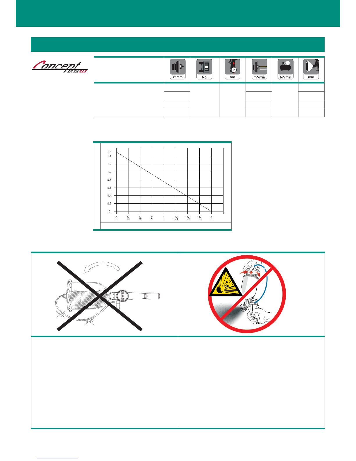
Iwata AZ3 HTE P.A.S. Concept User manual

en it fr es pt de se
• AZ3 HTE P.A.S.
with Pressurized Cup 600ml
USE and MAINTENANCE INSTRUCTION MANUAL
GRAVITY
SPRAY GUN Series

2
AZ3 HTE P.A.S.
TECHNICAL DATA
Technical
AZ3 HTE P.A.S.
1.3
HTE-P1 2.5
190
286
270
1.5 160 320
1.8 396 380
2.0 410 400
CAUTION Do not lay the gun down. The air regulator can be damaged if
paint flows backwards.
ATTENZIONE Non capovolgere la pistola. Altrimenti il regolatore aria potrebbe
essere danneggiato dal flusso di ritorno della vernice.
AVERTISSEMENT
Ne pas renverser le pistolet. Autrement le régulateur d’air,
pourrait être endommagé du flux de retour de la peinture.
PRECAUCIÓN No vuelques la pistola. El regulador de aire podría ser dañado del
flujo de retorno de la pintura.
ATENÇÃO Não deitar a pistola.O regulador de ar pode ser danificado com o
regresso da pintura.
VORSICHT Bitte die pistole nicht im befüllten zustand auf die seite legen.
Das luftregulierventil kann durch rückfliessendes material
beschädigt werden.
VARNING Lägg ej ned pistolen på sidan. Luftregulatorn kan skadas av att
färg kommer in i luftslagen.
GB Do not open the lid while pulling the trigger.
IT Non aprire il coperchio mentre si preme il grilletto.
FR Ne pas ouvrir le couvercle de godet quand on appuie sur la gachette.
ES No abra la tapa al tiempo que tira del gatillo.
PT Não abra a tampa enquanto a puxar o gatilho.
DE Nicht oeffnen waehrend der Abzugsbuegel betaetigt wird.
SV Öppna inte locket med avtryckaren intryckt.
Pressure Inside Cup (bar)
Turns of knob
Refer Chapter 5.5 “HOW TO ADJ. PRESSURE INSIDE CUP”
DIAGRAM TO ILLUSTRATE PRESSURE REGULATION INSIDE CUP
IMPORTANT INFORMATIONS

3
EN
IMPROPER USE
1. Never point gun towards people or animals.
2. Never exceed maximum working pressure or maximum operating
Temperature
3. Always release air and fluid pressure before cleaning, disassembling
or servicing. Otherwise, remaining pressure can cause bodily injury due to
improper operation or scattering of cleaning liquid.
4. Tip of fluid needle set has a sharp point.
Do not touch the tip during maintenance to avoid accidents.
5. Never use this gun to spray foods or chemicals. Otherwise, foreign sub-
stance, could cause corrosion of fluid passages which could adversely affect
health.
6. Never alter this spray gun, to avoid insufficient performance and damage.
7. If something goes wrong, immediately stop operation and find the cause.
Do not use again, until you have solved the problem.
8. Do not enter working areas, where robots, reciprocators, etc. are used,
until they have been turned off. Otherwise, they could cause injury.
3. HOW TO CONNECT
CAUTION
- Use clean air filtered through air dryer and air filter.
- When using this gun for the first time after purchase, adjust fluid needle
packing set, spray cleaner to clean fluid passages and remove rust pre-
ventive oil.
- Firmly fix cup to spray gun, to avoid that disconnection of it, can cause
bodily injury.
1. Firmly connect an air hose to air nipple G1/4” (17).
2. Firmly connect a suitable cup to fluid nipple G1/4”(15).
3. Flush fluid passages with a compatible cleaner.
4. Pour paint into container, test spray, adjust fluid output and pattern width.
4. HOW TO OPERATE
_ Suggested atomizing air pressure is 2.0 to 3.0 bar (29 to 44 PSI) at gun inlet.
_ Paint viscosity differs according to paint property and painting conditions.
_ Set the spray distance from the gun to the work piece, as near as possible
within the range of 100-200 mm (3.9-7.9 in).
_ The gun should be held so that it is perpendicular to the surface of the
workpiece at all times. Then, the gun should move in a straight and horizon-
tal line. Arcing the gun causes uneven painting.
2. SAFETY WARNING
FIRE AND EXPLOSION
1. Never use the following HALOGENATED HYDROCARBON SOLVENTS:
which can cause cracks or dissolution of gun body (aluminium) due to
chemical reaction. UNSUITABLE SOLVENTS: methyl chloride, dichloromethane,
1.2-dichloroethane, carbon tetrachloride, trichloroethylene,
1.1.1-trichloroethane
2. Sparks and open flames are strictly prohibited. Paints can be highly
flammable and can cause fire. Do not expose to open flames, electrical
goods, cigarettes etc.
3. Securely ground spray gun using conductive air hose. (Less than1M:)
Always ensure that the spray gun is earthed correctly.
PROTECTION OF HUMAN BODY
1. Use in a well-ventilated site, using a spray booth.
Poor ventilation can cause organic solvent poisoning and fire.
2. Always wear protective gear (safety glasses, mask, gloves) to avoid
inflammation of eyes and skin.
In case of any physical discomfort, immediately seek medical advice.
3. Wear earplugs if necessary.
Noise level can exceed 85 dB(A), depending on operating conditions and
painting site.
4. Pulling the trigger many times during operation, may cause carpal
tunnel syndrome. Always rest, in case of tiredness.
This AIRGUNSA spray guns kit complies
to ATEX regulations 2014/34/EU.
Protection level: II 2G X Suitable for using Zones 1 and 2.
X marking: Any static electricity discharge from the spray gun is to be diverted to
the ground via the conductive air hose as stipulated.
ALWAYS observe WARNINGS and CAUTIONS in this
instruction manual.
Before use, adjustment or maintenance, it is important
to read this instruction manual very carefully.
This manual must be stored in a safe place for any future
reference.
Symbol WARNING Hazard level Consequence
WARNING
Potentially hazardous
situation Death or serious injury
CAUTION
Potentially hazardous
situation
Minor to moderate injury
IMPORTANT
Potentially hazardous
situation Property damage
AZ3 HTE P.A.S.
1. TECHNICAL SPECIFICATIONS
Max. working air pressure:
7.0 bar (100 PSI)
Max. air pressure inside cup:
1.5 bar (21.76 PSI)
Weight g (lbs): (without cup)
730 (1.61)
Noise level (LAeqT)*:
77.6 dB(A)
Air Connection
G1/4”
Fluid Connection
G1/4”
Max. Temperature range:
Atmosphere 5 ~ 40 °C / Air-Fluid 5 ~ 43 °C
* Measuring point: 1m backwards from gun, 1.6 m height.

4
- When you remove needle packing nut (10), don’t
leave the two plastic parts of needle packing set
in the gun body.
- Try to adjust it carefully while pulling trigger and
confirming movement of fluid needle set (9).
- If you tighten it too much, repeat operation.
e. Disassembly of pattern adjustment set (5) and/or air adjustment set (14).
In order to disassemble pattern adj. set (5) and/or air adj. set (14), turn
manually turn the hexagon knob of the adjustment counter-clockwise to
open it completely and unscrew the hexagon face with a spanner turning it
counter-clockwise.
- To reassemble pattern adjustment set (5) and/or air adjustment set (14),
reverse the procedure.
IMPORTANT: Before reassembling pattern adjustment set and/or air
adjustment set, make sure that these operations are carried out with the
adjustment fully open.
5.3 HOW TO FILL THE CUP
5.4 HOW TO ADJUST SPRAY PATTERN
5.5 HOW TO ADJUST PRESSURE INSIDE CUP
EN AZ3 HTE P.A.S.
5. MAINTENANCE AND INSPECTION
CAUTION
- Never use spare parts that are not AIRGUNSA originals.
- Never damage fluid nozzle tip, fluid needle or air cap holes.
- Never immerse the spray gun completely in liquids such as thinner.
5.1 CLEANING PROCEDURE
- Never soak air cap set (1) in cleaning liquid for an extended period,
even when cleaning.
- Never use metal brush to clean the gun.
1. Drain remaining paint from spray gun and cup, into a suitable container.
2. Pour cleaner into cup.
3. Unscrew air cap (1) by 2 turns, to allow atomizing air to back flush, fluid
passages of the gun.
4. Pull trigger (13) and make sure, that atomizing air enters cup.
5. Leave cleaner for a few seconds, then empty it into suitable waste con-
tainer.
6. Repeat procedure above, until spray gun is clean.
7. Remove air cap (1) and cup from gun, then clean each section with brush
soaked with cleaner and wipe out with waste cloth.
8. DRY ALL PARTS completely and apply spray gun lubricant to each thread.
5.2 MAINTENANCE
BEFORE DISASSEMBLY, CLEAN FLUID PASSAGES.
a. Disassemble fluid nozzle (2), while keeping fluid needle (9) pulled (triggering)
in order to protect its seat section.
b. Disassemble fluid needle set (9). (only when strictly necessary)
c. Remove the fluid adj. knob (6) and needle spring (8), extracting the spring and
fluid needle set (9), from the back of fluid adj. guide (7) set still assembled on
the gun body.
d. Adjustment of the needle packing set, must always be carried out with fluid
needle (9) still assembled, tightening the nut with a properly spanner, making
sure that excessive tightening does not impede movement of fluid needle (9),
resulting in paint leaking from fluid nozzle tip (2).
The fluid passages of the gun, must be cleaned thoroughly
after each use, especially after use with bi-component paints.
Incomplete cleaning can cause defective pattern shape.
Before carrying out maintenance and inspection ALWAYS
observe warning indications.
PATTERN ADJUSTMENT
(for all models)
Left turn (L)= LARGE pattern
Right turn (R)= SMALL pattern
AIR FLOW ADJUSTMENT
a. b. c.
d.
e. f.
Turn the knob clockwise to
increase pressure inside cup.
Turn the knob counter-clockwise
to reduce pressure inside cup.
Increase
Decrease

5
EN
AZ3 HTE P.A.S.
7. SPARE PARTS LIST
6. TROUBLESHOOTING
GUN DOES NOT SPRAY
- Fluid adj. knob (6) closed. Check and adjust.
- Tip hole of nozzle (2) obstructed. Check and clean.
- Paint filter obstructed. Check and clean.
- Non drip obstructed. Check and clean.
INTERMITTENT SPRAY PATTERN
- Air escapes from fluid nozzle. Check , clean & replace if
necessary.
- Air escapes from fluid needle Tighten.
packing (10).
- Air escapes from cup joint. Tighten.
- Dirt inside air cap (1). Clean.
DEFECTIVE SPRAY PATTERN
- Dirty nozzle (2) or air cap (1). Clean carefully.
- Nozzle (2) or air cap (1) Replace if damaged.
has been damaged.
- Fluid nozzle (2) is loose. Tighten.
- Paint viscosity too high or Dilute paint or increase
too low. viscosity
- Fluid output too high or Adjust fluid adj. knob (6)
too low. to reduce or increase.
LEAKING
- Fluid nozzle (2), needle set Clean or replace if neces-
(9) or gun body, dirty, sary.
damaged or worn on seat.
- Dirt inside air cap (1). Clean.
- Loose fluid adj. knob (6). Adjust.
- Fluid needle spring (8) is Replace.
worn.
- Loose fluid nozzle (2). Tighten.
- Needle packing set (10) loose, Adjust, clean or replace.
too tight, dirty or worn.
AIR ESCAPES FROM AIR CAP
- Air valve (11-2), air valve Clean or replace if neces-
seat (11-3) or air valve sary.
spring (11-1) dirty or damaged.
6.1 INSPECTION & REPLACEMENT STANDARD
REF. DESCRIPTION
1 AIR CAP SET
2 FLUID NOZZLE
3 NOZZLE HOLDER
S
5 PATTERN ADJUSTMENT SET
6 FLUID NEEDLE ADJ. KNOB
7 FLUID NEEDLE GUIDE
S
8 NEEDLE SPRING
9 FLUID NEEDLE
10 NEEDLE PACKING NUT
11 AIR VALVE SET
11-1 AIR VALVE SPRING
11-2 AIR VALVE
11-3 AIR VALVE SEAT
12 TRIGGER STUD
13 TRIGGER
14 AIR ADJUSTMENT SET
15 THREADED BUSHING
S
16 PLUG
17 AIR NIPPLE
S
19 PRESSURIZED GRAVITY CUP SET (600ml)
19-1 PRESSURIZED CUP
19-3 LID
19-4 STRAIGHT MALE ADAPTOR
19-5 AIR HOSE
20 PRESSURE REGULATOR SET
20-1 ORIENTING RING
20-2 BANJO STEM SINGLE
20-3 PRESSURE REGULATOR
C PACKING SET
D SLIDE RING SET
E NON DRIP
F LID PACKING
WHERE TO INSPECT REPLACEMENT PART
a. Each hole passage of air cap
(1) and fluid nozzle (2).
Replace if it is crushed or deformed.
b. Packing and O ring Replace if it is deformed or worn out.
c
.
Leakage from seat section
between fluid nozzle (2) and
fluid needle set (9).
Replace them if leakage does not stop
after fully cleaning fluid nozzle (2) and
fluid needle set (9).
If you replace fluid nozzle (2) or fluid
needle set (9) only, fully matchthem and
confirm that there is no leakage.
15
19
19-4
19-3
19-1
19-5
F
C
C
E
123 5
7
9
86
17
1413
11
11-2
11-3
11-1
16
10
12
12
20-1
20-2
20-3
20
D
S
Remove the following parts, only in case of repair and by qualified
personnel.
Table of contents
Other Iwata Paint Sprayer manuals

Iwata
Iwata NEO TRN1 User manual

Iwata
Iwata Eclipse G3 User manual

Iwata
Iwata PT2S User manual

Iwata
Iwata Full Finish G-Series G6 Instruction Manual

Iwata
Iwata Custom Micron B User manual

Iwata
Iwata LPH-440-141 User manual

Iwata
Iwata Kustom K9200 User manual

Iwata
Iwata Revolution TR1 Manual

Iwata
Iwata NEO BCN User manual

Iwata
Iwata Custom Micron CM-B User manual