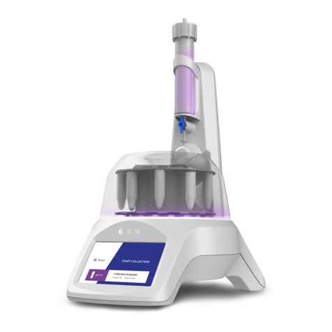
Izon EXOID User manual

www.izon.com
EXOID
USER MANUAL

Increased output with minimal intervention. Incorporating
the unparalleled accuracy of tunable resistive pulse
sensing (TRPS) into a semi-automated machine with
improved sensitivity and usability, the Exoid represents a
reliable method of measuring individual particles. At Izon
Science, we are committed to helping you get an accurate
measurement of your particles, here we will help guide
you through this process to get the best possible data
from your Izon Exoid.
2www.izon.com

1 DEFINITIONS AND WRITING CONVENTIONS ...................................................4
2 SAFETY AND HAZARDS...........................................................................................6
Safe Use Requirements and Specifications.......................................................................... 6
Hazards..................................................................................................................................................6
3 INTRODUCTION TO THE EXOID.............................................................................8
Overview................................................................................................................................................8
Fluid Cell V2........................................................................................................................................ 10
Intended Use...................................................................................................................................... 10
Important Information ....................................................................................................................11
4 ASSEMBLY AND SETUP INSTRUCTIONS.......................................................... 12
Instrument power and general operation........................................................................... 12
General Operating Procedures................................................................................................. 12
Assembling and Installing the Exoid....................................................................................... 13
Connecting to a computer........................................................................................................... 13
5 OPERATING INSTRUCTIONS ................................................................................ 15
Initial Connection ............................................................................................................................. 15
Investigation Details....................................................................................................................... 16
Nanopore Setup............................................................................................................................... 16
Sample analysis ............................................................................................................................... 18
Guide to real time data................................................................................................................. 19
Guide to real time system metrics........................................................................................... 21
Sample Changeover ...................................................................................................................... 21
Nanopore and System Cleaning.............................................................................................. 21
6 TYPES OF ANALYSIS ............................................................................................. 22
Concentration and size measurements............................................................................... 22
Size and zeta measurements ................................................................................................... 22
7 MANUALLY CONTROLLING SYSTEM PARAMETERS ................................... 25
Stretch................................................................................................................................................. 25
Applied Pressure ............................................................................................................................26
8 TROUBLESHOOTING .............................................................................................28
9 FURTHER SUPPORT............................................................................................... 33
TABLE OF CONTENTS
3www.izon.com

SYMBOL MEANING
This symbol indicates general advice on how to improve procedures or
recommends measures to take in specific situations.
This symbol indicates where special care should be taken.
24V DC/4.17A Direct Current (DC)
Voltage polarity of the jack
Crushing Hazard
Make sure to follow the precautionary statements presented in this guide. Safety
and other special notifications will appear in boxes and include the symbols
detailed in Table 1.
Table 1: Safety and Hazard Symbols
DEFINITIONS AND WRITING CONVENTIONS1 /
4www.izon.com

Table 2: Terminology used in this manual
TERM DEFINITION
Baseline drift The amount of current (nA) that the current moves by over a period
of time.
Blockade duration A measurement of the velocity of the particle, critical for Zeta
analysis.
Blockade frequency Directly proportional to the particle concentration, higher
concentrations will have a higher particle rate.
Blockade magnitude Directly proportional to the particle size. The amount of current
that a particle blocks as it goes through the nanopore.
Calibration Aliquot of diluted calibration particles of a known size.
Exoid buttons The buttons near the top of the Exoid, to control the stretch.
Electrolyte A liquid which contains ions and can transmit a current when
voltage is applied.
Exoid Control Suite (ECS) The software used to operate the Exoid.
Exoid lighting Lighting halo located around the top of the Exoid.
Load position When the stretcher unit is at the position which enables a
nanopore to be clipped on to the teeth.
Measurement The complete sample analysis, made up of multiple recordings.
Nanopore Flexible polyurethane membrane with a nanoscale size hole in the
centre.
Nanopore type Nanopore size classification see section 3.
Recording One part of a whole measurement, particles (sample or calibration)
run at one set of parameters.
RMS noise Background electrical noise of the system.
Sample The unknown particles to be analysed using the Exoid system.
Shielding lid Hinge-able cap on the top face of the Exoid which opens to
reveal the fluid cell and nanopore working area. Closing this will
reduce noise from external sources such as large machinery and
fluorescent lighting.
Stretcher unit A set of jaws with teeth which the nanopore can clip on to.
5www.izon.com

Safe Use Requirements and Specifications
Make sure to adhere to the safe use requirements as specified in the table
below. In the event that the equipment is used in a manner not specified, the
protection provided by the equipment may be impaired.
SAFETY AND HAZARDS2 /
SAFE USE REQUIREMENT SPECIFICATION
Operating
Temperature
Indoor Use Ambient temperature of 5-40 ˚C is safe for the
instrument, however Izon recommends operating at
5-25 ˚C.
Altitude Up to 2,000 meters above sea level
Relative Humidity 20-80% relative humidity
Power Consumption 80 W
Pollution Degree Rating 2
Ingress Protection Rating IP30 / Type 1 - UL50E
Power Supply Unit
(TRH100A240-21E11
+ CCCVI)
Input AC 100-240 V
1.5 A
47/63 Hz
Output DC 24 V nom
4.17 A max current
100.08 W max power
Hazards
The Exoid is a laboratory product, however if any biohazardous samples are
present then adhere to current good lab practices (cGLP) and comply with any
local guidelines specific to your laboratory and location.
6www.izon.com

Fire or Electrical Hazard
The Exoid poses no uncommon electrical or fire hazard to operators if installed
and operated properly without physical modification and connected to a power
source of correct specification.
Chemical Hazards
The Exoid system contains no potentially hazardous chemical materials.
Mechanical Hazards
The Exoid stretcher unit contains automatically moving parts. Keep fingers
and loose clothing clear while automatic processes are in operation.
Transport
Before moving or shipping the Exoid, decontamination procedures must be
performed. Always move or ship the Exoid with the supplied packaging materials
which will protect the instrument from damage, and use appropriate heavy object
lifting techniques so as to avoid injury. If appropriate packing materials cannot be
obtained then contact your local Izon Science office.
Disposal
The Exoid system contains electrical or electrical materials; it should be disposed
of as unsorted waste and must be collected separately, according to the European
Union Directive: Waste Electrical and Electronic Equipment. The user is fully
responsible for ensuring that the obsolete Equipment and/or Consumables are
recycled or disposed of in accordance with this and/or any other relevant laws and
regulations in the countries where the instrument is being recycled or disposed of.
Contact your local Izon Science representative for more information.
7www.izon.com

INTRODUCTION TO THE EXOID3 /
Overview
Characterisation of particles using Tunable Resistive Pulse Sensing (TRPS) provides
a reliable and accurate method of measuring size, concentration, and surface
charge. It is the only technology that can deliver the concentration of particles in fluid
as a number per volume across a specified detectable size rage, as well as calculate
effective surface charge of individual nanoparticles. The Exoid eliminates many of
the inaccuracies associated with nanoparticle analysis with its advanced technology
and automated systems.
TRPS technology uses the Coulter particle counting principle on the nanoscale.
Voltage is applied across the fluid cell via the silver/silver chloride electrodes,
therefore creating a baseline current due to the flow of electrolytic ions. A temporary
decrease in current is detected as particles pass through the nanopore, which allows
for the sizing and counting of particles suspended in electrolyte.
Figure 1. A schematic representation of how TRPS works within the Izon system.
Nanopore
Lower fluid cell
Upper fluid cellParticle flow
Ag/AgCl Electrode
Ag/AgCl Electrode
Electrolyte
Cations
Anions
Electrolyte
8www.izon.com

HALO COLOUR EXOID STATUS
White Connected, idle.
Red Disconnected, see troubleshooting.
Blue System requires user input.
Purple System performing an operation.
The Exoid uses automated systems to improve the speed and accuracy of the
system as a whole. The automatic stretcher unit (also referred to as Delta) can
stretch the nanopore cruciform up and down faster than mechanically winding by
hand, saving time in a high throughput environment. The buttons near the top of the
Exoid can control the stretcher unit in the event that access to the manual software
control is no longer available.
The Automatic Pressure System (APS) applies a pressure far more accurate
than that of the previous Variable Pressure Module (VPM) system as it can read
and adjust itself to the operator entered value without any further input from the
operator. The APS is also capable of applying pressures (positive and negative) 50%
greater than that of the VPM.
Visual indications of the state of the Exoid using the Exoid lighting allow the user to
immediately assess how the system is functioning.
Decrease Stretch No Function Increase Stretch
9www.izon.com

Fluid Cell V2
The Exoid system comes with a new and improved fluid cell design. A dedicated
return path built into the electronics of the fluid cell and improved shielding mean
that the entire system is more resilient to external noise interference. This new
design is also less susceptible to the “short circuits” that plagued the original fluid cell,
making for easier troubleshooting.
The new design has two pogo pins on the lower fluid cell
which fit into sockets on the underneath of the upper fluid
cell when twisted into place correctly. To assist with this,
the upper fluid cell has two position indicators on each side
which, when installed correctly, will be half obscured by the
lower fluid cell.
Intended Use
The Exoid is used to automate nanoparticle analysis of samples, to give size,
concentration, and surface charge data. The instrument is intended to be used
in research laboratories by professional personnel. The Exoid is not intended for
diagnostic purposes and should not be used to make treatment decisions.
For verification of the entire system, it is recommended that Good Laboratory
Practices (GLP) be followed to ensure reliable analyses.
10 www.izon.com

Important Information
Pipetting
While using the Exoid it is important to employ correct pipetting practices. For all
particle and sample dilutions the user should use forward pipetting, reverse pipetting
should be used when pipetting into the upper fluid cell. For more information on these
two pipetting techniques visit support.izon.com/pipetting-techniques
Choosing a Nanopore
Choosing the right nanopore size will depend on the target particle size of the sample to
be measured. The table below provides some guidance on how to select a nanopore.
— 40-255 nm
— Calibration: CPC70, 100
— Target Conc. /mL: 1x10¹⁰
— 185-1100 nm
— Calibration: CPC400, 800
— Target Conc. /mL: 5x10⁸
NP80 NP400
— 70-420 nm
— Calibration: CPC100, 200
— Target Conc. /mL: 5x10⁹
— 385-2050 nm
— Calibration: CPC800, 1000
— Target Conc. /mL: 1x10⁸
NP150 NP800
— 110-630 nm
— Calibration: CPC200, 400
— Target Conc. /mL: 2x10⁹
— 935-5700 nm
— Calibration: CPC2000, 4000
— Target Conc. /mL: 5x10⁶
NP250 NP2000
— 50-330 nm
— Calibration: CPC100, 200
— Target Conc. /mL: 5x10¹⁰
— 275-1570 nm
— Calibration: CPC800, 1000
— Target Conc. /mL: 5x10⁸
NP100 NP600
— 85-500 nm
— Calibration: CPC200, 400
— Target Conc. /mL: 2x10⁹
— 490-2900 nm
— Calibration: CPC1000, 2000
— Target Conc. /mL: 5x10⁷
NP200 NP1000
— 150-900 nm
— Calibration: CPC200, 400, 800
— Target Conc. /mL: 1x10⁹
— 1990-11300 nm
— Calibration: CPC4000
— Target Conc. /mL: 5x10⁵
NP300 NP4000
11www.izon.com

ASSEMBLY AND SETUP INSTRUCTIONS4 /
Instrument power and general operation
Make sure the power supply box is positioned away from fluids
To prevent heat build up do not cover the power supply box
Position the unit so it can be quickly and easily disconnected from the mains power.
Check the local supply meets the AC input requirement given in the specification.
Izon instruments are only to be operated with Izon supplied leads and power
supplies. Failure to use the correct power supply may result in invalid operation.
Make sure the power supply is placed away from the instrument and to the rear
of the instrument to avoid coming into contact with any spills or fluid.
General Operating Procedures
For indoor use only and to be used within the rated conditions noted in system
specifications.
Take care not to spill fluids on electrical parts during operation.
12 www.izon.com

Assembling and Installing the Exoid
1. Unpack the Exoid and box contents
We recommend that you save the box and packaging materials in case the
instrument needs to be returned for servicing.
The Exoid must be installed into Earth Grounded Protected Outlets ONLY. Position
equipment away from electrical switching gear and interfering equipment or noise
may increase under sample running conditions.
2. Place the Exoid onto a stable and level laboratory bench.
3. Ensure that the buttons near the top of the Exoid are facing the user.
4. Connect the power lead to the 24 V power supply.
5. Make sure the power is off at the wall and at the Exoid before plugging the power
lead into a wall socket and connecting the cable from the 24 V power supply to
the rear of the instrument.
6. Connect the USB cable to the instrument and the computer.
7. Turn the instrument on first using the power switch at the wall socket and then
the power switch on the Exoid.
Connecting to a computer
Devices that can be connected to the equipment should be compliant with a
relevant safety standard such as IEC 60950-1 for IT equipment or IEC 61010-1 for
laboratory equipment and should provide double or reinforced insulation
from hazardous voltage sources. Always use Izon supplied USB cables to connect
to the instrument.
13www.izon.com

Computer Minimum specifications
Windows (7 onwards) Professional Edition (64-bit)
i7 processor
16 GB RAM
Dedicated graphics processor and memory (1 GB)
Hard drive with at least 50 GB free space for software installation and data
One free USB port
Windows Home Edition is not suitable for the installation of the ECS. Ensure
that the computer is installed with Windows Professional Edition.
On board graphics is not suitable for the operation of the Exoid. Ensure that
the connected computer has a dedicated graphics processor with at least 1 GB
of memory. Please contact Izon Support if this is an issue.
To operate the Exoid, there are two software suites that must be installed. The Exoid
Control Suite (ECS) is used to control the Exoid and gather data. The Izon Data Suite
(IDS) is a separate software required to analyse the data collected in the ECS. Both
software packages for non 21 CFR Part 11 installations can be downloaded from the
link below.
support.izon.com/how-can-i-get-the-latest-exoid-control-suite-software-release
14 www.izon.com

OPERATING INSTRUCTIONS5 /
Initial Connection
If using a laptop to operate the Exoid, ensure that the laptop charging cable is
plugged in and providing power at all times during operation of the instrument.
Once the instrument is connected to the computer according to the earlier
instructions, open the ECS. A welcome splash screen followed by the home screen
will be displayed, showing a render of the instrument with the word “Connected”
beneath it. There are several internal mechanics of the Exoid which need to have
completed their start-up process before this will occur. A successful connection
of all components will also be indicated by activation of the Exoid lighting. If either
the lights or the “connected” are not displaying, please refer to the troubleshooting
section at the end of this document. Notifications about system updates appear at
the top right of the screen.
15www.izon.com

Investigation Details
This is where the user will populate the name of the investigation they will be
performing that day, as well as allow the user to load a “Calibration File” from the
computer if they are using a nanopore which has already completed the setup
process.
Nanopore Setup
This section guides the user through all the appropriate procedures required to
prepare the nanopore for sample analysis. This includes loading, wetting, coating
(if applicable) and characterisation. This is recommended for all nanopores and will
save a “Calibration File” to the computer which can be loaded into the ECS in the
“Investigation Details” screen if the nanopore is used again after the software has
been closed for any reason.
Nanopore Loading
Follow the on-screen instructions for loading the nanopore. A correctly loaded
nanopore is one where the serial number is facing upwards, and all arms are fitted
snugly onto the stretcher unit teeth. At this stage, the user will have the option to
“resume previous setup” if for some reason the software has been closed before
nanopore setup has been completed.
Nanopore Wetting
The user will also be guided through wetting the nanopore as part of the nanopore
loading procedure. User dialogue will appear on the right-hand side of the screen,
with prompts on what actions to take next and what information to fill in. At most
steps there will be the option to cancel and go back at any time. As part of the
wetting process, the nanopore will also go through a “soak” phase. This phase allows
the baseline to stabilise after it has wetted, meaning that baseline drift will be at a
minimum for the characterisation of the nanopore. The Exoid will do this automatically
once the user has followed the setup prompts, if there are any issues during this
process then the ECS will notify the user that intervention is required. The user will
then be required to inform the system whether or not their sample is of a biological
nature. If yes then they will proceed to coating, if no they will proceed to nanopore
characterisation.
16 www.izon.com

Nanopore Coating
The user will be prompted to perform nanopore coating in the event that the
analysis is being performed on samples of a biological nature. The user will inform
the system if this is the case and then will be guided through the protocol via the on-
screen instructions.
Izon coating solution prevents non-specific binding of biological nanoparticles to
the nanopore membrane, skipping this step will increase chance of blockages and
decrease the life of the nanopore. Izon coating solution powder is available for
purchase with the Izon Reagent Kit, which will also provide all other reagents needed
for nanoparticle analysis on the Exoid.
Nanopore Characterisation
The Exoid will then automatically characterise the nanopore based on fitting an
analysis of the current at different stretches to a pre-determined model. After this
step, the user will be asked to load calibration particles of a certain size in order to
calibrate the nanopore.
Once this has been achieved, the user will be informed which particles that
particular nanopore is suitable for measuring. Once this step is complete then the
user will be taken back to the home screen where they can then start their analysis.
17www.izon.com

Sample analysis
If there is no nanopore information currently stored in the system then the user will
be asked to confirm that their nanopore has been set up correctly upon initiation of
sample analysis, if there is already nanopore information stored in the system then
this step will automatically be skipped. The next step in sample analysis is for the user
to choose which type of analysis they wish to perform. Upon selection of analysis type,
the user will be asked to enter their sample details, as well as choosing the target
analysis size range with the slider bar on the next prompt screen. Data collection is
started by selecting “Start Analysis,” post system optimisation. During data collection
the user should not have to interact with the system at all, providing the conditions
are stable. The ECS will automatically stop recordings at 500 particle count before
moving on to the next pressure step.
The ECS will guide the user through analysing the sample, the first step being to run a
calibration for the system.
18 www.izon.com

Calibration is an absolute requirement to obtaining meaningful size and
concentration data. The calibration collection will happen in much the same way
as the sample collection, just follow the on-screen instructions and the ECS will do
everything else automatically.
While a recording is in progress the user will have access to three options, “Pause
Analysis,” “Cancel” and “Advance.” The pause option allows the user to pause
the collection of data. The advance option allows the user to manually finish the
recording and save the data before the automatic recording length has been
reached. The cancel button allows the user to return to the previous step.
While a recording is paused, the user is able to “Resume Analysis,” and “Restart Run.”
Resuming will begin data collection from the point it was paused at, while restarting
will begin data collection from the start of that particular pressure measurement,
discarding any data that was already collected for that pressure only.
Guide to real time data
Trace and particle size plot
This is the visual representation of baseline current, RMS noise, and blockade
magnitude. The user is able to alter the scale of both the X and the Y axis by pressing
either the + or – magnifying symbols next to the appropriate axis. Zooming in on the
Y axis will allow the user to see more detail in the variability of the baseline trace, but
will make it more difficult to visualise if the baseline is stable or not, or distinguish the
particles from the noise by eye. Zooming out will give a much better visual for the
particle blockades, however zooming out too far will make it extremely difficult to
detect an increase in RMS noise quickly.
19www.izon.com

Zooming in or out on the X axis will change the time period displayed over the course
of the plot. Zooming in will mean that the trace moves much faster as the time
period is shorter, while zooming out will mean that the trace moves much slower as
the time period is longer.
Below the trace plot is the particle size plot. This displays each significant blockade
event as a dot, plotted against a relative particle size scale which will display in
nano amps (nA). This is an important visualisation as blockades that are too small
run the risk of not being fully detected by the ECS. Here the particles visualised as
dots will line up with their corresponding blockade event. Also displayed here is RMS
noise, total particle count, and particle rate.
Both plots can be “popped out” to be bigger by selecting the Full Size button in the
top right of the signal trace plot. Similarly, once it has been popped out, it can be
popped back in by pressing the Reduced Size button.
Particle size distribution histogram
This graph is located to the right of the particle size plot when the trace is popped
out, it will display the size distribution of the unknown particle being analysed on the
Exoid in real time.
20 www.izon.com
Other manuals for EXOID
2
Table of contents
Other Izon Laboratory Equipment manuals