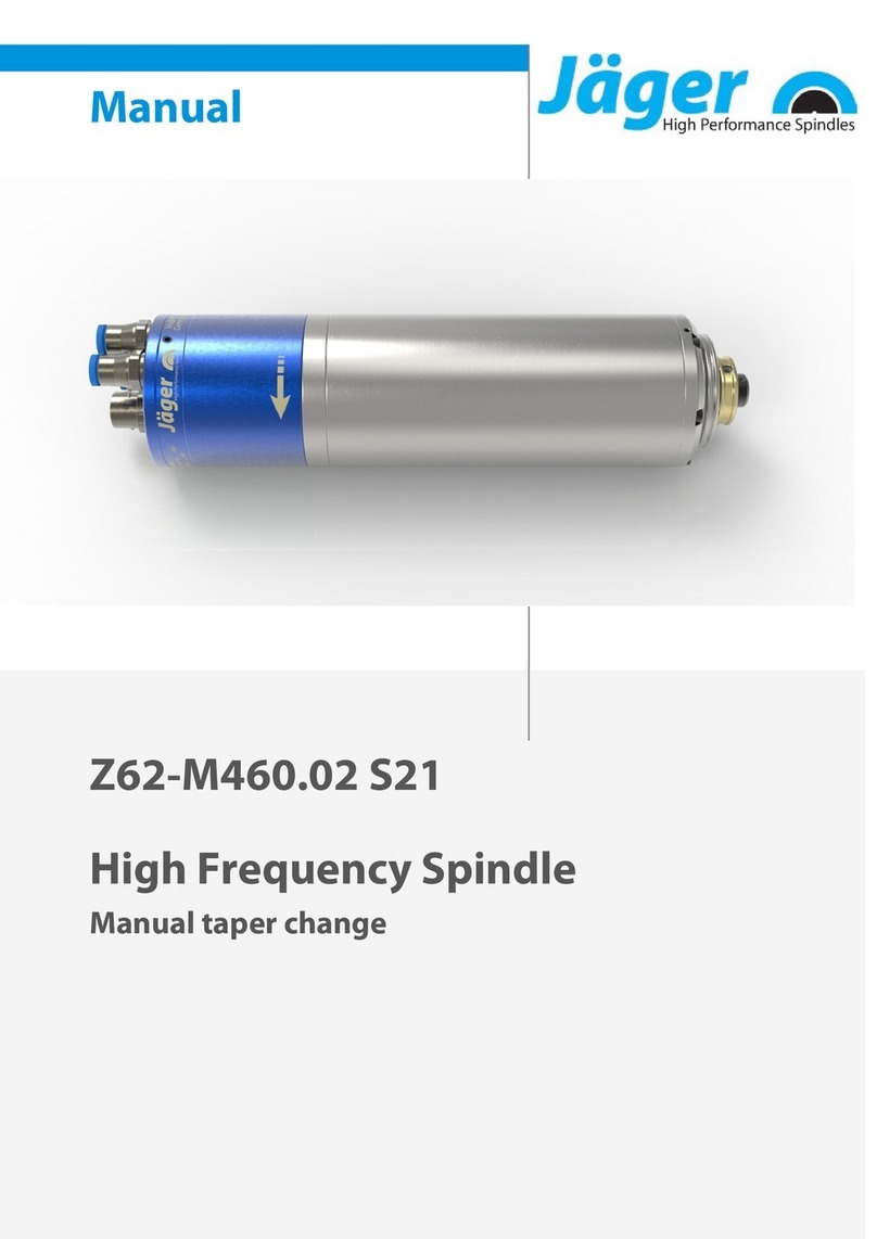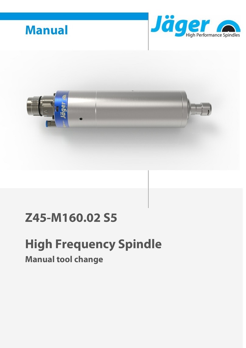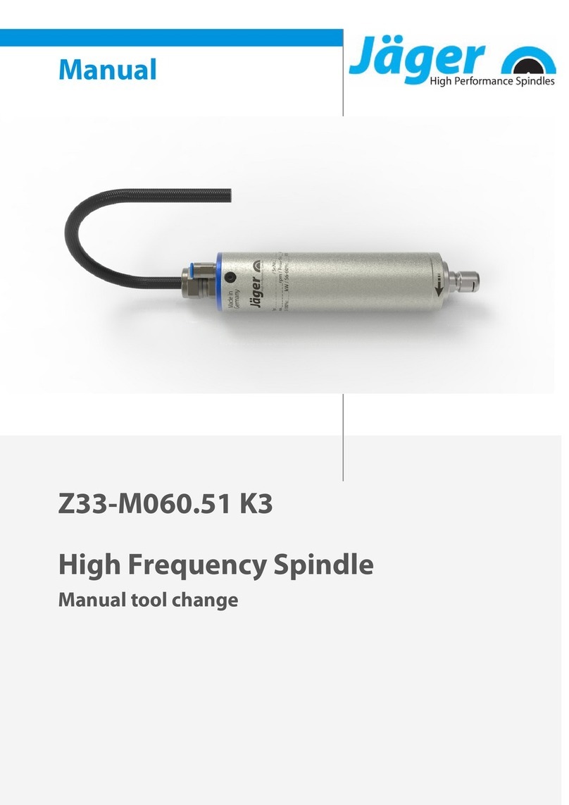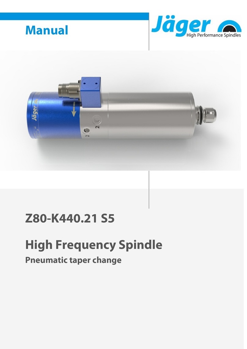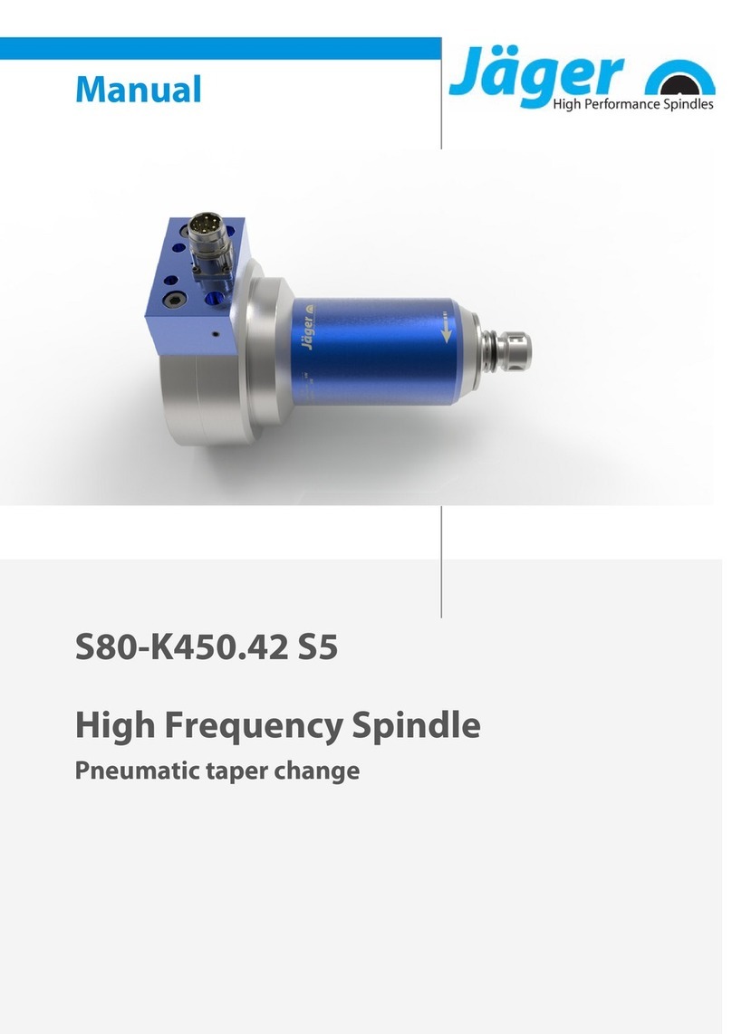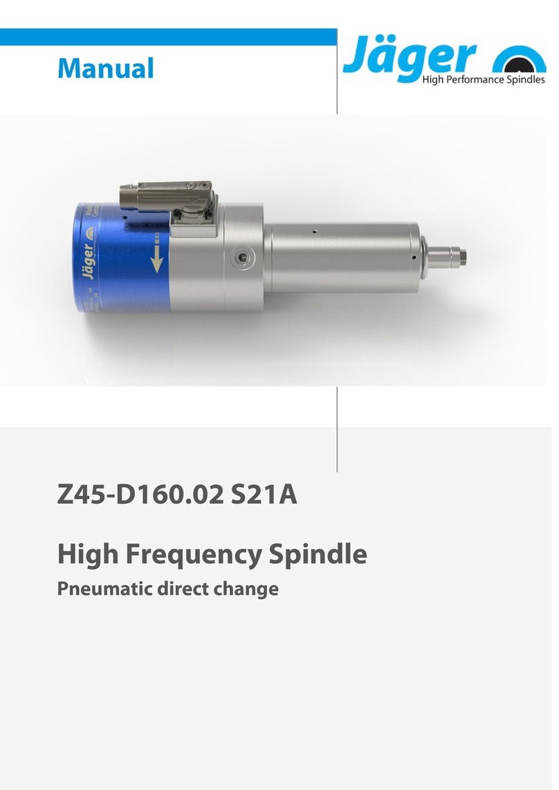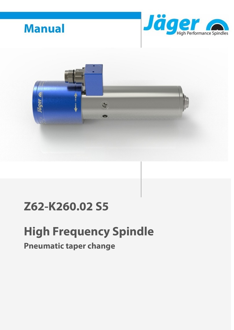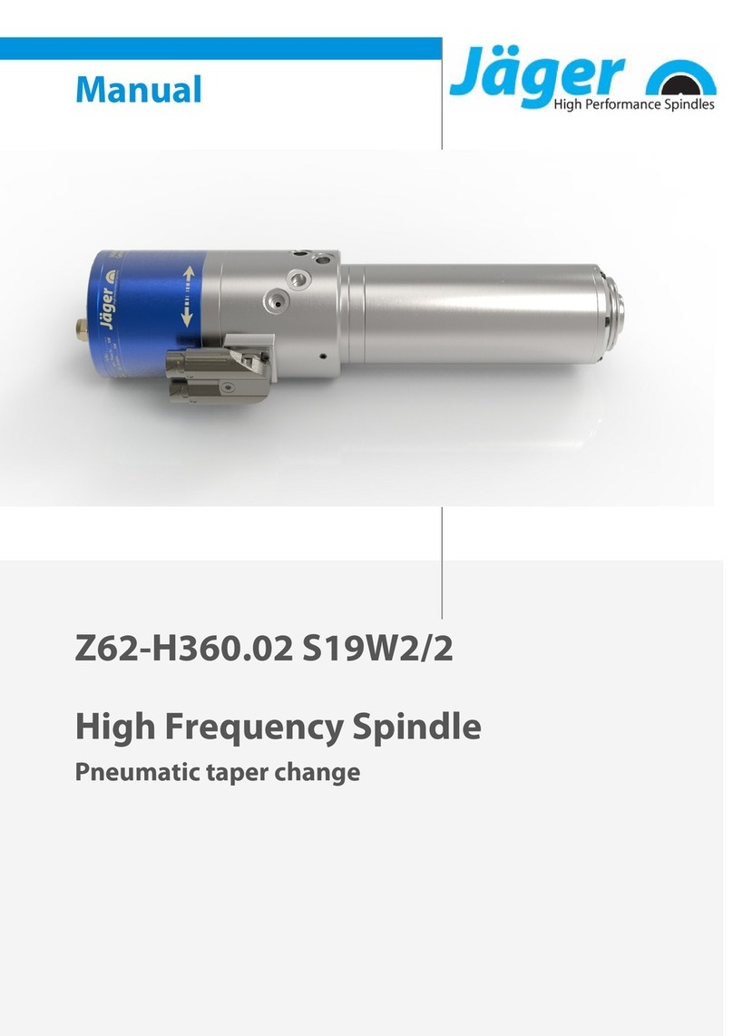
Item no. 10405047-03, Revision 03 3 ( 48 )
Contents:
Translation of the original manual
1 Preliminary information 5
1.1 Purpose of the manual ...................................................... 5
1.2 Explanation of symbols used .......................................... 5
2 Transport and packaging 6
2.1 Scope of supply of HF spindle ........................................ 6
2.1.1 Optional accessories............................................. 6
2.1.2 Documentation supplied.................................... 6
2.2 Packaging of HF spindle.................................................... 7
3 Designated use 7
3.1 Permissible types of machining ..................................... 7
3.2 Permissible materials ......................................................... 7
4 Safety instructions 8
4.1 Safe working.......................................................................... 9
4.2 Shutdown of HF spindle .................................................10
4.3 Installation and maintenance .......................................10
4.4 Modification and repair...................................................10
4.5 Improper operation..........................................................10
5 Technical description 11
5.1 Connections of HF spindle.............................................11
5.2 Electrical connection........................................................12
5.3 Cooling..................................................................................12
5.4 Sealing air.............................................................................12
5.5 Taper cleaning....................................................................12
5.6 Pneumatic tool change ...................................................12
5.7 Internal coolant supply ...................................................13
5.7.1 Cooling lubricant .................................................13
5.7.2 Filtering the cooling lubricant ........................14
5.7.3 Avoiding pressure peaks...................................14
5.8 Leakage.................................................................................14
5.8.1 Internal coolant supply, vertical installation
....................................................................................15
5.8.2 Internal coolant supply, horizontal installa-
tion............................................................................15
6 Technical Specifications 16
6.1 Dimensions..........................................................................17
6.2 Technical data sheet (KL7007 , AC-Motor) ...............18
6.2.1 Performance Diagram........................................19
6.3 Wiring diagram...................................................................20
6.4 Motor protection PTC 160°C..........................................22
6.5 Tool change monitoring.................................................22
6.6 Displacement measuring system (Ott-Jakob).........23
6.6.1 Technical Specifications....................................23
6.6.2 Signals......................................................................24
6.6.3 Installation..............................................................24
6.6.4 Scaling......................................................................25
6.7 Speed and position sensor (MiniCoder)....................25
6.7.1 Technical Specifications....................................25
6.8 Air-borne noise emissions..............................................26
7 Operating location 26
8 Installation 27
8.1 Installing the HF spindle .................................................27
8.2 Diameter of media supply line .....................................28
8.3 Cooling water......................................................................28
8.3.1 Quality of cooling water....................................28
8.3.2 Setting the cooling..............................................28
8.4 Compressed air...................................................................29
8.4.1 Air purity classes (ISO 8573-1).........................29
8.4.2 Setting the sealing air ........................................29
8.4.3 Setting values........................................................30
8.5 Setting the internal coolant supply ............................30
8.6 Sensor electronics of measuring system (optional
accessory).............................................................................31
8.6.1 Wiring of measuring system............................31
9 Commissioning 32
9.1 Running-in schedule ........................................................32
9.2 Daily start-up.......................................................................33
9.3 Shutdown signal................................................................33
9.4 Commissioning after storage........................................33
10 Tool change 34
10.1 Clockwise and counter-clockwise ...............................34
10.2 Pneumatic taper change ................................................35
10.2.1 Automatic hollow shank taper tool clamp
....................................................................................35
10.3 Tool changing station (optional accessory).............36
10.3.1 pneumatic taper change...................................36
10.3.2 Installing the changing station.......................36
10.3.3 Maintenance..........................................................36
10.4 Workflow ..............................................................................37
10.4.1 Pneumatic workflow...........................................37
10.4.2 Electrical workflow ..............................................38
