jablotron JA-80Y User manual

The JA-80Y GSM communicator - 1 - MFJ55304
The JA-80Y GSM communicator
The communicator is a component of the Jablotron Oasis 80 system.
This manual is valid for software version XA61010 or higher. The
communicator is designed to be installed within the control panel
housing. When connected to a GSM network it allows the following:
• event reporting by SMS (to up to 8 telephone numbers)
• event reporting by phone call with an acoustic warning
• event reporting to an ARC (Automatic Receiving Centre – also known
as a Central Monitoring Station) - up to 2 ARCs
• remote control and programming by phone (remotely authorizing a
phone keypad or by SMS instructions)
• the remote control of appliances in the house by dialling in from an
authorized number (free of charge with unanswered calls)
• remote control and programming via the Internet (www.GSMlink.cz)
• connecting a phone set = simulated tel. line = GSM gateway function
(incl. CLIP protocol = caller ID and SMS transfer)
• listening-in and voice communication – via a connected SP-02
intercom
• connecting a PC to the Internet (GPRS modem feature)
1. Installation in the control panel
If you purchased the communicator module separately, it should first be
installed in the Oasis control panel as follows:
a) the control panel power must be switched off (both mains and
battery)
b) Fit the communicator inside the control panel housing using screws
and connect its cable to the main board
c) attach the adhesive GSM antenna to inside the control panel’s
plastic housing (on the lower internal wall) and connect the antenna to
the communicator – never switch the control panel power on if the
GSM antenna is not connected to the GSM module as this will cause
serious damage.
d) connect the relevant cables to the communicator if you intend using
the simulated telephone line, the AUX output or a PC serial data
cable for the GPRS modem function
SYMBO
L
SPACE
CANCEL MENU NAMES CA LLS WRITE READ
123
456
789
0#
2
SMS
CALL
MUTE
FLASH
REDIAL
SPEAKER
SMS phone
connected to
RJ socket or
PHONE
terminals
AUX relay
terminals
Internet
connection
via COM port
GSM antenna
Fig. 1 Communicator wiring
2. Powering up the communicator for the
first time
If the communicator is installed in the control panel and its GSM antenna
is connected then:
a) have a suitable SIM card ready. It should be activated (see if it
works in a mobile phone first). If it requires a PIN code when turning
the phone on, then disable the PIN code request (for example in
Nokia via: Menu / Settings / Security settings / PIN code request /
Off). The communicator can work with a prepaid card, but for more
reliable functioning use a tariff card (see 5.16).
b) insert the SIM card into the communicator (to open the card holder
push its frame up a little)
c) switch on the control panel power (mains and battery). The
communicator’s red LED should go off within a minute = successful
registration to the GSM network.
If the red LED starts flashing after awhile, switch off the control panel
power, put the SIM card into a mobile phone and check that it
registers to the network in place of the control panel and without any
PIN code requests.
d) close the control panel cover, the alarm system should be in
Service mode - if it is not, enter ∗0 Service code (factory default:
8080) with the alarm system unset (disarmed).
e) key in 98101 - to set texts of the communicator to English language.
f) key in 922 to measure the GSM signal strength (should indicate in
the range 0/4 to 4/4). It should be at least 2/4 for reliable functioning.
If the signal is weak, change the location of the control panel or try a
SIM card from another GSM provider (it is not recommended to use
either a high-gain or directional antenna– see 5.2).
g) if the GSM signal is sufficient, test the communicator functions
(for example calling the system’s SIM card number and authorizing
the phone keypad you are using) – see 3.3.
If installed at a location near a national border where roaming to a
foreign network is highly likely (e.g. when the signal strength is
fluctuating), we recommended blocking the roaming feature in the SIM
card to avoid unnecessarily high communication fees. Contact your GSM
provider for details.
3. User functions of the communicator
The following text describes all communicator features. The installer
should show the end user how to operate the functions used in a
particular installation.
3.1. Making a phone call from a connected phone
The communicator provides a simulated phone line (including CLIP
protocol) to connect a phone set:
• the phone (tone dialling only) should be connected to the telephone
socket on the communicator board (or to the PHONE terminals)
• the phone can be used as if connected to a standard telephone line
(factory default settings of the communicator)
• if the phone supporting SMS messages is used, then besides phone
calls it is also possible to send and receive SMS messages (see
5.11.1)
• the communicator terminates current phone calls if it is due to
send event reports
• some phone sets are sensitive to nearby GSM radio signals. If you
hear strong interference in the phone receiver caused by the
communicator’s GSM signal, change the location of the phone set.
3.2. Listening-in and voice communication
If listening-in and voice communication are needed, then an SP-02
intercom should be connected to the phone line simulated by the
communicator. The intercom can be connected in parallel to any existing
phone set. The SP-02 works as a speaker-phone which answers calls
automatically when coming from telephone numbers authorized to
access the listening-in feature. The SP-02 also provides a push-to-talk
feature to call a number stored in its memory. See the SP-02 manual for
details on how to authorize numbers to listen-in, and how to program the
push-to-talk number.
3.3. Temporarily authorizing a phone keypad to be a system
keypad
It is possible to operate the system remotely by temporarily authorizing a
phone keypad as follows:

The JA-80Y GSM communicator - 2 - MFJ55304
a) dial the system’s SIM card number (if a phone is connected to the
communicator’s simulated line it will start ringing)
b) after 25 seconds of ringing (programmable) the system will answer with
a short beep
c) key in a valid access code on the telephone keypad (e.g. 8080 or 1234
if factory default settings are still valid)
d) the phone keypad will behave as a system keypad and an acoustic
signal in the receiver will indicate the control panel status: 1 beep =
SET, 2 beeps = UNSET, 3 beeps = Service mode, 4 beeps = incorrect
code entry, siren sound = alarm
e) now the system can be operated from the phone keypad the same way
as from the system keypad – including the commands starting with ∗(for
example ∗81 to turn the PGX output on)
f) to exit this mode simply end the phone call (if nothing is entered within
a minute, the phone call will end automatically anyway)
Notes:
do not enter sequences on the phone too fast, each key signal
needs a certain time to be sent (it depends on the particular phone and
the quality of the GSM connection)
a fixed-line phone can also be used to operate the system remotely
the same way (the phone must use tone dialling)
the system can also be operated from the keypad of a phone
connected directly to the communicator’s simulated line. It is only
necessary to pick up its receiver and briefly press the # key. Then the
phone is ready to work as a control panel keypad. To finish operating
just hang up.
Phone keypads have to be re-authorized each time the system is
called by entering the codes specified earlier, as phone keypads are
only authorized as system keypads for the duration of a call to the
system.
3.4. SMS instructions to control the system remotely
All incoming SMSes are checked by the communicator and if there are
any instructions to the system, they will be performed. Each instruction
message must have the following format:
code instruction
(valid code space instruction)
Valid code = any valid code in the system (e.g. 8080, 1234 etc.)
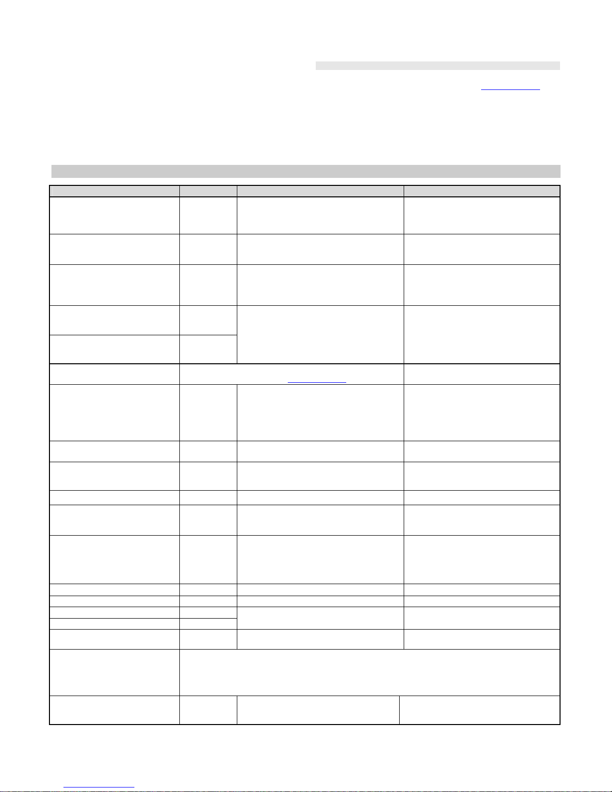
The factory-default instruction texts (editable – see 5.5)
Instruction Function Note
SET setting (arming)
UNSET unsetting
(disarming)
setting or unsetting (the same way as
if the used code is entered on the
system keypad), If the system is
already in the desired mode, it will not
change
STATUS status
interrogation including GSM signal strength, GPRS
data, ARC communication (shown as
MS1 and MS2)
MEMORY last event
interrogation The last event recorded in the control
panel memory
PGX ON turns on PGX
PGX OFF turns off PGX
PGY ON turns on PGY
PGY OFF turns off PGY
the PG output has to be programmed
for the function: on/off (by 237/247) or
2 second switching (by 238/248)
AUX ON turns on AUX
AUX OFF turns off AUX turns a pair of AUX terminals on the
communicator module on/off
CREDIT SIM card credit
interrogation it has to be initialised by SMS before it
can function – see 5.17
Example: by sending: “code SET” (valid code space SET) the system
will set (if it is already set it will not change its status)
Notes:
performance of the instruction is confirmed by an SMS reply
the instruction texts are not case-sensitive and only ASCII characters
are allowed
only one instruction can be in an instruction SMS
a setting/unsetting instruction starting with the service code will only be
performed if setting/unsetting with the service code is enabled in the
control panel (to protect against unauthorized setting/unsetting by
installers)
an SMS instruction can also be sent to the alarm system from a phone
connected to the communicator (if supports SMS) – to phone number
001 (for free)
if there is any other text in the instruction not separated by “%”, the
instruction will not be performed
if you are sending an instruction and you are not sure whether any
other text will be automatically added to the SMS (for example, when
using an SMS internet gate) type the instruction as: %code
instruction%%
3.5. Toll-free remote control by unanswered calls from pre-
authorized phones
A limited number of system functions can be activated remotely by
calling the system from pre-authorized phones and terminating calls
before the system answers. This way limited control of the system is free
of call charges. It is possible to pre-authorize phone numbers stored in
memories M1 to M8 (also used for event reporting – see 4).
To pre-authorize a telephone number store ∗at the end of the number
and follow it by a single digit (1, 2, 3, 8 or 9) – see the notes in section 4.
If this number calls, the communicator generates “∗digit“ after the first
ring (as if it had been entered manually on the system keypad). This toll-
free remote control by unanswered calls enables the following functions
according to the digit stored at the end (after the *) of the tel. number in
memory:
∗1setting the complete system (= ABC keypad button)
∗2setting section A (= A button)*
∗3setting sections A & B or B (= B button)*
∗8PGX turns on for 2 sec. (if PGX is programmed for the pulse
function)
∗9PGY turns on for 2 sec. (if PGY is programmed for the pulse
function)
Notes:
if a phone sends no caller identification data it cannot be used for
this type of remote control by phone
if phone calls end before the control panel answers, remote control is
for free
a phone which is pre-authorized for toll-free remote control can also
temporarily authorize its keypad to fully operate the system (see
3.3) – just let it ring until the control panel answers the call
if it is desired that the phone which is authorized for toll-free remote
control should not receive event reports, then turn the reports off for
that tel. number (see 5.4).
setting (arming) with ∗1, ∗2 and ∗3 will work only if enabled in the
control panel
4. Reporting to phones
The communicator can report events occurring in the Oasis system by
sending SMS reports and/or by calling phone numbers with an acoustic
signal (mostly used as audible notification of an SMS to be read). Reporting
can be programmed for up to 8 phone numbers.
The most frequently desired reports are already assigned to the telephone
number memories by factory-default, so you only need to program tel.
numbers to the particular memories which have the desired reports already
assigned. If desired, other events can be reported to the number too, i.e. the
list of event reports assigned to the number can be changed (see 5.4)
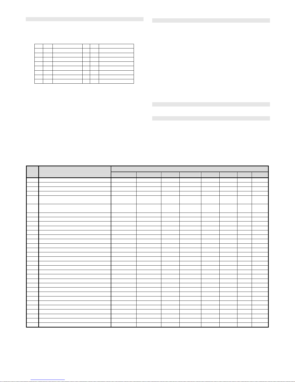
Factory-default reports assigned to the numbers M1 to M8
M Reports
1
2 Alarms and faults by SMS
3
4 Alarms and faults by SMS + phone call (if you answer the
call you hear a siren sound)
5
6 Alarms by SMS + a phone call, with Setting/Unsetting
and faults by SMS only
7 Alarms by phone call (if you answer the call you hear a
siren sound)
8 Technical fault by SMS (suitable for an installer)
To program phone numbers to the M memories, enter the following
sequence while in Service mode:
81 M xxx...x ∗0
where:
M is memory 1 to 8
xxx...x is a phone number (max. 20 digits)
Example: entering 81 5 777 777 777
∗
0 will store the number
777777777 in memory M5 (Alarms will be reported by SMSes + phone
calls, Setting/Unsetting and faults only by SMS)
To erase a number from memory M enter: 81 M ∗0
Notes:
Entering ∗9before the first digit will insert a “+” for the international
formatting of phone numbers

The JA-80Y GSM communicator - 3 - MFJ55304
if it is desired that the events be reported to the SMS phone connected
to the communicator then program tel. number 001 into the memory
SMS report text consists of: installation name, event name, number and
name of the event source (device or code), date and time. Example:
“Report from your alarm: setting 47: device Time 01.08. 11:27”
if other events or texts should be reported to a particular number,
change the communicator settings (see 5.4 and 5.5)
when storing tel. numbers, if you key in ∗7 after the last digit of the
phone number (the symbol ∗is also stored) and continue with one
more digit (1, 2, 3, 8 or 9), then if this tel. number calls the system, the
system will behave as if ”∗digit“ had been keyed in just after the first
ring, i.e. as if it had been entered manually on the system keypad –
see section 3.5. Example: entering 81 5 777 777 777
∗
79
∗
0
authorizes calls from tel. number 777777777 to trigger output PGY for
2 seconds (after the first ringing signal from this number the ∗9
command will be executed. The PGY output should be programmed for
a 2 sec. pulse function. This setting is suitable for opening an electric
door lock, automatic gate etc.
4.1. Programming
The most convenient programming is best done by a PC running
Comlink software or via the Internet and website: www.GSMLink.cz or by
programming SMS – PRG sequence
Programming is also possible via the system keypad:
The control panel must be in Service mode - if it is not, enter ∗0 Service
code (factory default: 8080) while the system is unset.
Enter the relevant programming sequences – see the following description
To exit service mode press the #key
5. Programming sequences
Function Sequence Options Factory default
Language setting 981 xx
xx=01 to 17 where:
01=EN,02=CZ,03=SK,04=NL,05=DE,06=PL,07
=DA,08=IT,09=PT,10=FI,11=NO,12=SV,
13=FR, 14=HU, 15=RU, 16=TR, 17=SP
English
GSM signal strength
measurement 922 On keypad or in ComLink software range 0/4 to 4/4
In reply to STATUS SMS: range 0/9 to 9/9
exit by pressing # -
Tel. number programming for
reporting to telephones
81 M xx..x ∗0
M= memory 1 to 8
xx..x = tel. number (max.20 digits)
keying in ∗9 = + and ∗7 = ∗
81 M ∗0 erases the number in memory M
all M1 to M8 erased
Selection of events to report by
SMS
82 M ec x
Selection of events to report by
phone call 83 M ec x
M= tel. number memory from 1 to 8
ec = event code (see 5.4)
x=1 report, x=0 no report
M1 & 2 alarms by SMS
M3 & 4 alarms by SMS and call
M5 & 6 alarms by SMS and call +
Set/Unset by SMS
M7 alarms by call
M8 technical faults by SMS (to installer)
SMS text editing* Texts can be edited by Comlink software or by SMS instruction:
code TXT n,text,n,text... or by www.GSMLink.cz via Internet see 5.5
Enable reporting to phones 80 x
x=0 disabled
x=1 enabled (all programmed by 82.. & 83..)
x=2 enabled without reporting
setting/unsetting by users 41 to 50 (codes,
cards & key-fobs) and master code
setting/unsetting
enabled
Remote access 903 x x=0 disabled
x=1 enabled (by phone and Internet) enabled
Forwarding of incoming SMSes 926 x x=0 no, x=1 yes = if the incoming text is not an
SMS instruction it will be forwarded to the first
programmed number in memories M1 to M8
yes
SMS instruction confirmation 927 x x=0 no, x=1 yes (by SMS reply) yes
Reaction to incoming calls 904 x x=0: no reaction
x=1 to 8: answers after 1 to 8 rings
x=9: answers after the 2nd call answers after 5 rings (25s)
Simulated phone line function 951 x
x=0 tel. line (GSM gateway)
x=1 alarm system keypad
x=2 off
x=3 automatically calls an emergency tel.
number when the tel. receiver is picked up
tel. line
Emergency tel. number 952 xx..x ∗0 xx..x = tel. number (max.20 digits) erased
GSM signal dropout indication 921 x x=0 no, x=1 yes (15min. dropout =Fault) no
Phone microphone sensitivity 953 x
Phone speaker loudness 954 x x=1 to 9 (9 = maximum) 5
Number to be periodically called
to maintain SIM card validity 924 xx..x ∗0 xx..x = tel. number (max.20 digits), 924∗0=erase erased
Using an SMS instruction to
configure automatic SIM card
credit interrogation *
Via an SMS instruction to the alarm system: code CREDIT uu..u xx yyy zz where code = master or service
code, uu..u = GSM network command string to ascertain the credit (e.g. ∗104#) , xx=auto-interrogation
frequency in days, yyy=minimum acceptable balance, zz= the textual position at which the number showing the
balance starts in the reply message from the GSM provider. If the credit is lower than the minimum, the
provider’s SMS will be auto-forwarded to numbers M1 and M8 for someone to top up the pre-paid SIM card.
Getting your www.GSMLink.cz
registration code sent to your
mobile phone 910 xx...x ∗0 xx..x = your mobile phone number -

The JA-80Y GSM communicator - 4 - MFJ55304
Automatic SIM card credit
interrogation
Credit balance checking is set by SMS instruction code_CREDIT_uu..u_xx_yyy_zz where uu..u =
instruction for the GSM network (e.g. ∗101#etc.), xx= period in days, yyy=minimum balance, zz=
the position in which the number showing the balance starts, If the reported credit balance is lower
than the set limit (yyy), the credit balance message from the provider will be forwarded to phone
numbers M1 and M8
Programming by SMS System can be programmed remotely via SMS instruction code PRG seq, seq,... where seq is
programming sequence set also from the keypad (e.g. 8080 PRG ∗08080,201,# set the 10s exit
delay)
Triggering re-registration to the
GSM network 923 The communicator will unregister from the GSM network and then re-register. Also possible via
the SMS instruction: code GSM. Code = master, user or service code
Communicator reset 98080 Resets to the factory default settings and erases all phone numbers, text will not be changed
Memorizing the SIM card’s PIN
code in the communicator 920 xx..x ∗0 xx..x = new PIN, sequence 920∗0 erases the
PIN (to use a SIM card with a disabled PIN) erased
Configuring the GPRS log-in
parameters*
by SMS instruction to the alarm system: code GPRS x..x,y..y,z..z where code = master or service code, x..x =
the APN, y..y = name, z..z = password (only enter the APN if the name and password are not required by the
GSM provider)
ARC main tel. number/IP address 01 a xx..x ∗0
ARC backup tel. number/IP
address 02 a xx..x ∗0
a=1=ARC1, a=2=ARC2, xx..x = tel. number
(max.20 digits) or IP address & port – for
example: 01 2 ∗8 192 168 001 123 08080 ∗0
(∗8= signifies an IP address, it must have 12
digits followed by a 5 digit port number).
Entering 01p∗0 or 02p∗0 will erase the
number/address
erased
Installation (alarm system) ID for
ARC use 03 a zz..z ∗0 a=1=ARC1, a=2=ARC2, zz..z = ID number
max. 8 digits 0 to 9 and ∗1=A to ∗6=F
(hexadecimal number) 0000
Selecting the ARC protocol 04 a x a=1 ARC1, a=2 ARC2
x=0 CID, x=1 SMS CID, x=2 IP CID CID
Selection of events to report to
ARCs 05 a ec x a=1 ARC1, a=2 ARC2
ec event code (see 5.27)
x=1 report, x=0 no report all events are reported
Defining the delay before data is
resent to an ARC 06 a x a=1 ARC1, a=2 ARC2
x=0 to 9 min. (0=immediately, without delay) 1 minute
ARC communication checking
period
(The time to wait after the last report
before performing an ARC
communication check)
07 a hhmm a=1 ARC1, a=2 ARC2
hhmm = hours and minutes after last report 2400 (24 hours after last report)
Enable ARC reporting (ARC2
backs up ARC1) 00 a x a=1 ARC1, a=2 ARC2
x=0 reports disabled, x=1 reports enabled, x=2
(only for ARC2) = ARC2 backs up ARC1 ARC reporting disabled
Recording reports sent to ARCs in
the control panel memory 08 x
x=0 no (only records ARC communication
faults, if communication checks are enabled)
x=1 yes (all reports except communication
checks)
yes
Indicate an ARC communication
fault if a report is not successfully
received by an ARC within 110
sec of transmission.
09 x x=0 no
x=1 yes no
IP address for data transmission 013 xx..x ∗0
IP address and port in format – e.g..: 013
∗8 192 168 021 123 08080 ∗0 (∗8 mark IP
address which must contain 12 digits, followed by
5 digits for the port.. Entering 013∗0 IP erase the
setting
77.104.220.129 7070
(img.jablotron.com)
Locking the ARC settings 901 xx..x ∗0
xx..x = an installer-defined locking code (4 to 8
digits). Entering this code and then exiting
service mode will lock the ARC settings
901∗0will erase the code (= permanently
unlocked)
Unlocked
Unlocking the ARC settings 900 xx..x ∗0 xx..x = the locking code used by sequence
901
ARC programming can be temporarily
enabled in service mode by entering this
sequence. It will then relock on exiting service
mode.
These parameters effect reporting to the ARC and it is impossible to change them if the ARC settings are locked.
*These parameters cannot be programmed from the system keypad, but they can be programmed by sending SMS instructions or by Comlink software.

The JA-80Y GSM communicator - 5 - MFJ55304
5.1. Language setting
Language of the text used by the communicator can be set by
instruction:
981 xx
Where:
01 EN English 10 FI Finnish
02 CZ Czech 11 NO Norwegian
03 SK Slovak 12 SV Swedish
04 NL Dutch 13 FR French
05 DE German 14 HU Hungarian
06 PL Polish 15 RU Russian
07 DA Danish 16 TR Turkish
08 IT Italian 17 SP Spanish
09 PT Portuguese
Note:
Set the language before editing the text in the system (change of
the language will change the text to the factory default)
Change of the language in the communicator will automatically
result in changing the language in the connected keypad (also the
wireless keypad if connected)
Set language will not be change when reset is performed
Example: by setting 98102 the Czech language will be set.
Factory default : 98101 = English
5.2. GSM signal strength measurement
Good quality GSM signals are necessary for the reliable functioning of
the communicator. Entering 922 starts GSM signal measurement. The
keypad then displays the signal strength in the range 1/4 to 4/4 and
measurement is repeated every second (indicated by beeps). This mode
allows a suitable location to be found for the control panel (or the GSM
antenna). Press the # key to exit GSM signal measurement.
The SMS reply to a STATUS interrogation now displays GSM signal
strength in the range 0/9 to 9/9.
The signal should read at least 2/4. In places with a weak signal we
recommended trying another GSM provider’s SIM card.
Warning: it is not recommended to use a high-gain or directional GSM
antenna to get a better signal, as this way the communicator would only
communicate with a single cellular base station and communication
would not be stable. Also be aware that the GSM system cannot work
properly if the distance from the cellular base station is longer than 30km
(even if the signal is strong enough) as the time delays in the data
exchange would be longer than acceptable to the GSM standard.
5.3. Programming tel. numbers for reporting to phones
See part 4.
5.4. Selection of the events reported to phones
The factory-default list of reported events and their assignment to
telephone numbers M1 to M8 can be altered by this sequence.
The complete list of reportable events is shown in the following table.
It is possible to select whether the event should be reported by an
SMS or by a phone call, or by both an SMS followed by a phone call
Each event has pre-programmed factory-default SMS text. These
texts can be edited (see 5.5). The acoustic signals for phone call
reporting are fixed and cannot be changed (e.g. an alarm is
indicated by a siren sound if a reporting call is answered)
List of events which can be reported to phones and their factory-default assignment to particular phone numbers
Phone number memory M
ec Event 1 2 3 4 5 6 7 8
01 Intruder alarm - instant S S SC SC SC SC C
02 Intruder alarm - delayed S S SC SC SC SC C
03 Fire alarm S S SC SC SC SC C
04 Panic alarm S S SC SC SC SC C
05 Number of permitted incorrect code-entries
exceeded S S SC SC SC SC C
06 Alarm triggered during control panel
power-up S S SC SC SC SC C
07 Tamper alarm S S S S S S
08 End of tamper alarm
09 End of alarm indication
10 Alarm cancelled by user S S S S S S
11 Setting S S
12 Unsetting S S
13 Partial setting S S
14 Codeless setting S S
15 External communication fault S S S S S S S
16 External communication restored
17 Fault S S S S S S S
18 Fault no longer present
19 Mains dropout longer than 30 minutes S S S S S S S
20 Mains dropout
21 Mains restored
22 Discharged battery S S S S S S S
23 Battery OK
24 Switching to Service Mode
25 Leaving Service Mode
26 PGX ON/OFF
27 PGY ON/OFF
28 Radio communication jamming present S S S S S S S
29 Internal communication fault S S S S S S S
30 Internal communication restored
31 Communication test
32 Unconfirmed alarm
• Factory-default report assignment: S = SMS, C = call, SC = SMS followed by a call
• External communication fault means a GSM network dropout longer than 15 minutes (if GSM network dropout indication is enabled)
• The SMS information about a new picture on the server is sent to all phone numbers which are set to get reported event number 01 “Intruder
alarm - instant”. This information contains a link to the new picture on the server.

The JA-80Y GSM communicator - 6 - MFJ55304
5.4.1. Assigning events to be reported by SMS to a particular
mobile phone number
To link events to being reported by SMS, enter:
82 M ec x
where M phone number memory 1 to 8
ec event code 01 to 32 (see the above table)
x 0 = no SMS report, 1 = SMS report
Example: if 82 8 03 1 is programmed and a fire alarm is triggered
(event 03 in the table), it will be reported by SMS to the phone number
stored in memory M8
5.4.2. Assigning events to be reported by phone call to a
particular phone number
To link events to being reported by phone call, enter:
83 M ec x
where M phone number memory 1 to 8
ec event code 01 to 32 (see the above table)
x 0 = no phone call, 1 = call
Example: if 82 1 03 1 is programmed and a fire alarm is triggered
(event 03 in the table), the phone number stored in memory M1 will be
called and if the call is answered, a siren sound will be heard.
Notes:
Phone call reports are mostly used as an audible notification to
alert the user of a detailed report sent by SMS
If both SMS + call reports are enabled for events, the SMS is sent
first and then the number is called afterwards. But total priority is
given to ARC reports if enabled (see 7.1 )
5.5. SMS text editing
The communicator contains various text strings which are used to
create SMS reports and also SMS instruction text. Language of the
text can be set – see 5.1. These text strings cannot be changed from
the system keypad, but they can be edited by Comlink software, via
the Internet (www.GSMLink.cz) or by sending the following SMS
instruction:
code_TXT_n,text,n,text,......n,text
where
code is a valid access code (e.g. factory defaults: 8080, 1234)
_ is aspace
TXT instruction to edit texts
n text number (0 to 611 see the following table)
, comma (or full stop)
text the new text (max. 30 characters) which will replace the
former text. It is invalid to enter a comma or a full stop inside
the text string, but a space is valid within the text string
Notes:
• A single TXT instruction can change multiple texts (limited only by
the maximum length of a single SMS)
• the communicator is not case-sensitive and it is recommended to
use only English ASCII characters (some networks do not support
non-English national characters)
• the communicator creates SMS reports with 5 parts: installation
name, event description, source (code or device) number (01 to 50),
source name, time and date
• the maximum possible length of an ASCII SMS is 160 characters
(only 70 characters for national characters). If this length is
exceeded, the report is sent as multiple SMSes
Examples: if the service code is 8080 then the SMS instruction:
8080 TXT 20,key fob Bob,21,Key fob Jane
changes the description (name) of the key fobs enrolled to addresses
20 and 21
8080 TXT 605,heating on,606,heating off
edits the text of the two instructions used to command the heating to
be switched on and off by the PGX output (the PGX output must be
programmed to have an ON/OFF function)

The JA-80Y GSM communicator - 7 - MFJ55304
Factory-default SMS report and instruction texts
n Factory text n Factory text n Factory text n Factory text
44 Device 332 Code 504 Panic alarm0 Report from your
alarm: 45 Device 333 Code 505 Invalid code-entries exceeded
1 Device 46 Device 334 Code 506 Alarm when power turned on
2 Device 47 Device 335 Code 507 Tamper alarm
3 Device 48 Device 336 Code 508 End of tamper alarm
4 Device 49 Device 337 Code 509 End of alarm indication
5 Device 50 Device 338 Code 510 Alarm cancelled by user
6 Device 201 Control panel 339 Code 511 Setting
7 Device 202 Service code 340 Code 512 Unsetting
8 Device 203 Annual inspection request 341 Code 513 Partial setting
9 Device 204 Communicator 342 Code 514 Codeless setting
10 Device 205 Keypad 343 Code 515 External communication fault
11 Device 206 ARC code 344 Code 516 External comm. restored
12 Device 300 Master code 345 Code 517 Fault
13 Device 301 Code 346 Code 518 Fault no longer present
14 Device 302 Code 347 Code 519 Mains dropout over 30 minutes
15 Device 303 Code 348 Code 520 Mains dropout
16 Device 304 Code 349 Code 521 Mains recovery
17 Device 305 Code 350 Code 522 Discharged battery
18 Device 306 Code 400 System status 523 Battery OK
19 Device 307 Code 401 Set 524 Switching to Service Mode
20 Device 308 Code 402 Unset 525 Leaving Service Mode
21 Device 309 Code 403 Exit delay 526 PGX
22 Device 310 Code 404 Entrance delay 527 PGY
23 Device 311 Code 405 Alarm 528 Radio jamming present
24 Device 312 Code 406 Service mode 529 Internal communication fault
25 Device 313 Code 407 Maintenance mode 530 Internal comm. restored
26 Device 314 Code 408 Partial setting 531 Communication test
27 Device 315 Code 409 Discharged battery 532 Unconfirmed alarm
28 Device 316 Code 410 Tamper alarm 601 SET
29 Device 317 Code 411 Alarm memory 602 UNSET
30 Device 318 Code 412 Fault 603 STATUS
31 Device 319 Code 413 Power fault 604 MEMORY
32 Device 320 Code 414 Unknown status 605 PGX ON
33 Device 321 Code 415 Time: 606 PGX OFF
34 Device 322 Code 416 Last event: 607 PGY ON
35 Device 323 Code 417 Credit unknown 608 PGY OFF
36 Device 324 Code 418 Credit: 609 AUX ON
37 Device 325 Code 419 (internal use only) 610 AUX OFF
38 Device 326 Code 420 Error while processing command 611 CREDIT
39 Device 327 Code 421 Output turned on
40 Device 328 Code 422 Output turned off
41 Device 329 Code 501 Instant alarm
42 Device 330 Code 502 Delayed alarm
43 Device 331 Code 503 Fire
Numbers 01 to 50 for devices and
codes are automatically generated by the
communicator so it is unnecessary to
enter them in the text
• The communicator always automatically puts numbers from 01: to 50: in front of Device or Code names.
• Texts 0 to 532 are used to create SMS event reports
• Texts 601 and 611 are SMS instructions (to control the system remotely by SMS)
• Text 419 is for the internal use of the communicator, never edit it !
5.6. Enabling reporting to phones
Event reports can be enabled as follows:
800 all SMS and call reports disabled
801 all SMS and call reports enabled
802 all reports enabled except reports of setting and
unsetting by users 41 to 50 (i.e. their codes, cards and
key fobs). This allows setting and unsetting done by report
recipients (owners, bosses, etc.) not to be reported.
Factory default setting: 801 all reports enabled
5.7. Remote access
Remote access (by phone or Internet) can be enabled or disabled:
9030 disabled
9031 enabled
Factory default setting: enabled
5.8. Forwarding of incoming SMS messages
This feature enables the automatic forwarding of incoming SMS
messages which contain no valid instructions to the system:
9260 messages are not forwarded, but the communicator sends
them by CLIP protocol to the simulated phone line
9261 messages are forwarded to the first programmed tel.
number in memories M1 to M8 (e.g. if numbers are only
programmed in M5 and M6, then messages will be
forwarded to M5). The tel. number from which the SMS
was received will be shown at the beginning of the
forwarded text.
Factory default setting: messages are forwarded
5.9. SMS instruction confirmation
If the communicator receives a valid SMS instruction, the instruction
sender will be made aware of its successful execution by the reception
of a conformation SMS sent by the communicator. This confirmation
can be disabled as follows:
9270 disabled
9271 enabled
Factory default setting: enabled
5.10. Reaction to incoming calls
The communicator’s reaction to incoming phone calls can be set by:
904 x

The JA-80Y GSM communicator - 8 - MFJ55304
where
x = 0 incoming calls are ignored
x = 1 to 8 the communicator will answer after x multiplied
by 5 seconds of ringing (e.g. x=4=20sec.)
x = 9 answers after a second call - first there must be
at least one ring, then a pause (10 to 45sec.) and
then just after the first ring of the second call, the
call will be answered
Factory default setting: 9045 – answers after 25sec. (about 5 rings)
5.11. The simulated phone line function
This sequence defines the function of the phone connected to the
simulated telephone line (if used).
98 y
where Function
y = 0 phone line –for making phone calls. If the # key is
pressed when the receiver is picked up, the phone
will work as an alarm system keypad
y = 1 the phone works as a system keypad, it is
impossible to make phone calls
y = 2 the telephone line is disabled
y = 3 emergency call –automatically calls a pre-
programmed number (see 5.12), just after the
receiver is picked up. Pressing the ∗key within 2
sec. after having picked up the receiver will switch to
a dial tone and will allow the user to make phone
calls
Note: while the communicator is occupied with reporting events, or it is
not registered to the GSM network, a busy signal is heard on the
connected phone.
Factory default setting: y = 0 = phone line
5.11.1.Using an SMS phone connected to the simulated line
A phone capable of sending and receiving SMS messages by CLIP
protocol can be connected to the simulated phone line. In the phone,
both the TX and RX numbers should be programmed to 1111.
If an SMS message is sent from this phone to the phone number
“001” it will go directly to the communicator (free of charge). This can
be used to send instructions to the system (e.g. text programming
etc.).
If the communicator is programmed to report to phone number 001
the reports will be sent to the attached phone via the simulated line
(free of charge).
If the attached phone provides caller identification (CLIP), then the
caller’s phone number will be shown on the display.
5.12. Emergency telephone number
If the simulated phone line is set to emergency call mode (see 5.11),
then after picking up the receiver the phone will automatically call a
number programmed by:
952 xx...x ∗0
where: xxx…x is a phone number (max. 20 digits), keying in
∗9 will enter “+” for international calls
To erase the number enter 952∗0
Factory default setting: the emergency number is erased
5.13. GSM signal dropout indication
This selectable feature monitors connectivity with the GSM network. If
enabled, it indicates problems and generates an external
communication fault report if there is a GSM signal dropout longer than
15 minutes.
9210 disabled
9211 enabled
Factory default setting: disabled
5.14. The microphone sensitivity of the phone
The sensitivity of the attached phone (or intercom) can be adjusted by:
953x where x can be from 1 to 9 (max.) – factory default = 5
5.15. The speaker loudness of the phone
The loudness of the attached phone (intercom) can be adjusted by:
954x where x can be from 1 to 9 (max.) – factory default = 5
5.16. Number to be called to maintain SIM card validity
If a prepaid SIM card is used and a lack of outgoing phone calls for a
certain period cancels the validity of the SIM card, then this function
offers the following: if there have been no outgoing phone calls within
the last 90 days, then the communicator automatically calls the
number programmed by this sequence, waits until the call is answered
and then after 10 sec. automatically hangs up.
924 xx...x ∗0 where xx...x = phone number
Notes:
• To erase this number enter 924
∗
0
• It is recommended to call cheap public services (e.g. weather
forecasts etc.) but not toll-free numbers.
Factory default setting: erased
5.17. Automatic SIM card credit interrogation
The communicator is capable of checking the credit balance of its SIM
card by interrogating the GSM network with an SMS containing a
recognized instruction string (if the network supports this feature).
There are two options: The credit balance can be checked when the
user requests it by sending an SMS instruction to the communicator, or
the communicator can be set to check it regularly itself. To configure
credit balance checking send an SMS in the format:
code_CREDIT_uu..u_xx_yyy_zz
where:
code valid master or service code (e.g. 8080 or 1234)
_ space
uu..u instruction recognized by the GSM network to check the
balance (e.g. ∗101#etc.)
xx automatic checking period in days
yyy minimum acceptable credit balance
zz the textual position in which the number showing the
balance starts in the reply message from the GSM
provider
In addition, a new way of SIM card balance checking is now available
for networks which do not support standard balance checking but
provide SMS reporting after each charged transaction. In this case you
can configure credit interrogation by sending the following SMS:
code_CREDIT_S_xx
where:
code is a valid master or service code (e.g. 8080 or 1234)
_is a space
Sis literally S or s (a distinguishing mark)
xx automatic checking period in days (optional)
Simultaneously, it is necessary to disable SMS forwarding and to
configure the number used to maintain SIM card validity (the SIM
validity-maintenance call number).
After performing the configuration you can check the balance anytime
by sending the CREDIT instruction. By specifying the xx part you also
request the checking to be performed automatically. On each check,
the communicator performs a charged call (to the SIM validity-
maintenance call number), and enables the forwarding of a single
SMS from the network operator to the first pre-programmed number.
Notes:
• If the reported credit balance is lower than the set limit (yyy), the
credit balance message from the provider will be forwarded to phone
numbers M1 and M8 to remind someone to top up the SIM card.
• If event 22 is programmed to be reported to any tel. numbers (M1 to
M8) then the message “Discharged battery of the communicator” will
be sent to these numbers if the credit balance is under the yyy limit.

The JA-80Y GSM communicator - 9 - MFJ55304
The telephone numbers M1 and M8 will also receive the GSM
provider’s replay.
• If only uu..u follows the CREDIT instruction (no xx yyy zz) then
periodic balance checking will not be performed, but the balance will
be checked immediately and the uu..u checking instruction will be
memorized, so that in future it will be possible to check the balance
just by sending the instruction code CREDIT.
Example: sending the SMS instruction “code credit
∗
101# 7 50 1”
causes the credit balance to be checked every 7th day (after the SMS
has been sent) and if the balance (starting with the first character in
the message from the GSM provider) is lower than 50 currency units it
will be reported.
Warning: the use of prepaid cards in the communicator is risky.
Some GSM providers block cards with enough credit but which are not
topped up frequently enough. We strongly advise the use of tariffed
SIM cards !!!
5.18. Remote programming by the SMS instruction
Instruction PRG can be used to send programming and operating
sequences to the alarm system:
code_PRG_seq,seq,seq...
where:
code is valid access or service code (e.g. 8080 or 1234)
_ space
seq programming sequence usually set via the keypad
Note:
• In the sequence can be used characters 0 to 9, ∗and #)
• When the valid instruction is received, communicator simulates
entering the keys on the keypad, comma in the SMS is taken as a
pause in the sequence entering
• System must be unset and switched to the service mode
• The number of sequences in one SMS is limited by the maximum size of
the SMS in the GSM network.
Example: by sending SMS 8080 PRG
∗
08080,201,# the exit delay will
be set to 10s
5.19. Registration code for www.GSMLink.cz
If remote access via the Internet is desired, then the system has to be
registered on the web page: www.GSMLink.cz
Each communicator has its own unique registration code, which is
printed on the label attached to the communicator module. This code
can also be sent by SMS to your mobile phone by the keypad entry:
910 xx...x ∗0 where xx...x is the tel. number to send the code to
Notes:
• It takes a certain time to receive the registration code (depends on
the current traffic in the network)
• The registration code has the format: xxxxx-xxxxx-xxxx
5.20. Triggering re-registration to the GSM network
After 923 has been entered, the communicator quits the GSM network and
then re-registers itself. This re-registration does not change any settings in
the communicator. It should be used after GSM network faults or data
collisions and in some networks it also has to be used after a blocked SIM
card has been unblocked by the GSM provider.
It is also possible (if the SIM card can still receive) to trigger GSM network
re-registration by sending the SMS instruction: code GSM (code =
master, user or service code).
5.21. Communicator reset
Entering 98080 returns the communicator to its factory default settings and
texts, erases all telephone numbers and disables reporting. The text will
not be changed.
5.22. Memorizing the SIM card’s PIN code in the communicator
It is recommended to use a SIM card with disabled PIN protection. If it is
impossible to disable the PIN, then it can still be used by entering the
following sequence (it must be entered after the control panel has been
powered up).
920 PIN ∗0
Example: if the SIM card PIN is 1234 enter 9201234∗0
Notes:
If the communicator does not register to the GSM network within
1 minute of the PIN being entered (this problem is shown by red
LED flashes), then you either entered a wrong PIN or the GSM
signal is too weak. In such a case:
o enter 920∗0 while in service mode (erases the entered PIN)
o disconnect the control panel power (mains and battery)
o take out the SIM card and try it in a mobile phone (it should
register to a GSM network when located at the control panel)
o if you know the right PIN code and there is a GSM signal
strong enough, put the SIM card back into the communicator,
turn on the control panel power and then enter the PIN code
(920 PIN ∗0) – the communicator should then register to the
GSM network (its red LED should turn off within a minute)
The communicator memorizes the PIN and it will use it
automatically whenever it registers to the GSM network.
If you are replacing the SIM card in the communicator with
another one and the former one used a PIN code, first switch the
control panel to service mode and enter 920∗0 to erase the
former PIN code. The SIM card can then be changed.
Note: The PIN code cannot be changed if the ARC settings are locked
Factory default setting: The PIN code is erased
5.23. GPRS log-in parameters
GPRS data communication (wireless Internet via a GSM network) is
used for remote access via the Internet and also for IP reporting to the
ARC. To use GPRS data it must first be enabled (activated) in the SIM
card (contact your GSM provider for details). Then the GSM network’s
GPRS parameters must be programmed by sending the following SMS
instruction to the communicator.
code_GPRS_ x..x,y..y,z..z
where:
code is a valid (master, user or service) access code (e.g.
8080 or 1234)
_ space
x..x APN (Access Point Name)
, comma
y..y username (do not enter if not required)
z..z password (do not enter if not required)
Notes:
Most public GSM networks only request an APN (do not enter y..y
and z..z parameters in this case)
The GPRS parameters can only be programmed if the system is in
service mode and the ARC settings are not locked
Factory default setting: APN = Internet
5.24. ARC phone numbers / IP addresses
Events can be reported to up to 2 ARCs (which can be independent or
ARC2 can work as ARC1’s backup). Each ARC can have its main and
backup phone numbers (or IP addresses) programmed with:
Main: 01 a xx....x ∗0
Backup: 02 a xx....x ∗0
where:
a1=ARC1, 2=ARC2
xxx...x tel. number (max. 20 digits)
or IP address and port – entry format example:
01 2 ∗8 192 168 001 123 08080 ∗0
where ∗8 (auto-converts to #) signifies an IP address
which must have 12 digits and must be followed by the 5
digits of the port number (no separators)
To erase atel. number / IP address enter: 01p∗0 or 02p∗0
If numbers / IP addresses are erased there will be no reporting to that
particular ARC
Note: the communicator first tries to send data to the main number /
address, if it is not successful it tries the backup.
Factory default setting: all tel. numbers / IP addresses erased
5.25. Installation (alarm system) ID for ARC use
The installation’s ID number which is sent to an ARC with every report
can be programmed with:
03 a zz..z ∗0
where: a1=ARC1, 2=ARC2

The JA-80Y GSM communicator - 10 - MFJ55304
zz..z installation ID number, max. 8 characters (0 to 9 and
∗1=A to ∗6=F - hexadecimal number)
Factory default setting: 0000 for both ARCs
5.26. Selecting the ARC communication protocol
To select the required communication protocol enter:
04 a x
where: a1=ARC1, 2=ARC2
x 0=Contact ID, 1=SMS CID, 2=IP CID
Notes:
• IP CID is the fastest of the above protocols and it also allows very
frequent checking of communication reliability with the ARC (e.g.
every 5 minutes)
• Contact ID protocol can be used with ARCs linked by standard
telephone lines (if they support Contact ID)
• If your ARC does not allow SMS CID or IP CID protocols, please
contact a Jablotron distributor for details on how to update your
ARC.
Factory default setting: Contact ID for both ARCs
5.27. Selection of events to report to ARCs
The system recognizes 32 different types of events - see the following
table. This sequence allows you to select which events are reported to
which ARC.
05 a ec x
where a 1 = ARC1, 2 = ARC2
ec event code 01 to 32
x 0 = no report, 1 = report
Factory default setting: all events are reported
ec Event
01 Intruder alarm - instant
02 Intruder alarm - delayed
03 Fire alarm
04 Panic alarm
05 Number of permitted incorrect code-entries
exceeded
06 Alarm triggered during control panel power-up
07 Tamper alarm
08 End of tamper alarm
09 End of alarm indication
10 Alarm cancelled by user
11 Setting
12 Unsetting
13 Partial setting
14 Codeless setting
15 External communication fault
16 External communication restored
17 Fault
18 Fault no longer present
19 Mains dropout longer than 30 minutes
20 Mains dropout
21 Mains restored
22 Discharged battery
23 Battery OK
24 Switching to Service Mode
25 Leaving Service Mode
26 PGX ON/OFF
27 PGY ON/OFF
28 Radio communication jamming present
29 Internal communication fault
30 Internal communication restored
31 Communication test
32 Unconfirmed alarm
Besides the events listed above, the communicator also reports some
events which are not selectable here (e.g. the annual inspection
request if enabled in the control panel = CID 1393)
5.28. Defining the delay before data is resent to an ARC
The communicator tries to send reports to the main number / IP
address, and if unsuccessful it then tries the backup number / IP
address. If still unsuccessful, it then tries to re-send the data to both
the ARCs again as before, but after a period defined by:
06 a x
where
a 1 = ARC1, 2 = ARC2
t is the period: 0=immediately, 1 to 9 = 1 to 9 minutes
Factory default setting: 1 min. for both ARCs
5.29. ARC communication checking period
The time to wait after the last report sent to an ARC before performing
an ARC communication check is set by this sequence. The
communication-checking event code is 31 (see 5.27). This sequence
programs how often the communication check is performed:
07 a hhmm
where
a 1 = ARC1, 2 = ARC2
hh hours
mm minutes
Notes:
• Checking reports are not sent in service mode
• IP CID protocol allows very frequent checking of ARC
communication (e.g. every 5 minutes).
Factory default setting:24 hours after the last report – for both ARCs
5.30. Enable ARC reporting (ARC2 backs up ARC1)
This sequence allows reporting to ARCs to be switched on/off and also
enables ARC2 to backup ARC1:
00 a x
where
a 1=ARC1, 2=ARC2
x 0=off, 1=on, 2= ARC2 backs up ARC1 (2 can only be
entered for ARC2)
Note: if ARC2 backs up ARC1 then it will only receive data if it is not
possible to deliver it to ARC1. A report containing “Communication
fault to ARC1” is then sent to ARC2 together with the first report to
ARC2.
Factory default setting: both ARCs = off
5.31. Recording reports sent to ARCs in the control panel
memory
This sequence enables the recording of every report successfully
communicated to ARCs in the control panel’s internal memory.
080 enabled
081 disabled
Note: it is recommended not to record reports sent to ARCs but to
enable the indication of ARC communication faults (see 5.32). This
saves a significant amount of control panel memory. The system
initially assumes that every report is successfully delivered to ARCs,
but if a report is not successfully delivered within 110 seconds of
transmission, then a communication fault will be indicated and
recorded.
Factory default setting: enabled
5.32. Indicate an ARC communication fault if a report is not
successfully received within 110 sec of transmission
Enables the indication and recording of a communication fault if a
report is not successfully delivered to an ARC within 110 seconds of its
transmission.
090 communication faults not indicated
091 communication faults indicated
Notes:
• The communicator continues trying to send information to an ARC
even after a communication fault has been indicated (after the data
has been delivered, communication fault indication stops).
• For communication-checking reports the delivery time limit
(confirmation from the ARC) is 300 minutes. But if any other report is
sent to the ARC it must be confirmed within 110 seconds (otherwise
a communication fault will be indicated)
Factory default setting: communication faults not indicated

The JA-80Y GSM communicator - 11 - MFJ55304
5.33. IP address for data transmission
The communicator supports transmission of special data (e.g. visual
information) from the system to the set IP address, which can be set
by the following sequence:
013 *8 xxx xxx xxx xxx yyyyy *0
where: concerning ∗8, insert these characters, to identify the
following IP address which must consist of 12 digits followed
by 5 digits for the port (see below)
xx..x is the12 digit IP address
y..y is 5 digits for the port (see manual of the communicator).
Example: 013
∗
8 195 039 077 154 07070
∗
0
To erase the IP set 013∗0.
Note: if no devices supporting this feature are in the system, do not set
the IP address.
Factory default : 77.104.220.129 7070 (img.jablotron.com)
5.34. Locking the ARC settings
All settings which effect reporting to ARCs can be locked by a digital
code:
901 xx..x ∗0 where xx..x is an installer-defined locking code (4 to
8 digits)
Notes:
• Exiting service mode after the locking code has been entered will
lock all the settings effecting ARC communication (see the
sequence list in section 5).
• If ARC programming is locked, then it can be temporally enabled in
service mode by entering 901 xx..x ∗0 where xx..x is the locking
code. It will then relock on exiting service mode.
• The ARC settings can be permanently unlocked by entering 901∗0
while ARC programming is temporally enabled – see above. This
will erase the locking code.
Factory default setting:ARC settings unlocked
5.35. Engineer reset supported
Starting from this version the communicator firmware supports the
Engineer reset feature (also requires the control panel firmware to be
of version KE60108 or higher). This feature is designed for ARC
(Alarm Receiving Centre) connection to satisfy the following
requirements of the DD243 standard: After a confirmed alarm has
been triggered, the control panel must switch to a disabled state.
Switching to normal operation is then only possible using a valid ARC
access code. Until then, the system remains completely disabled –
no operation or programming is possible even when in
Maintenance or Service mode.
An ARC access code can be entered in the following ways:
GSMlink in the field used for remote code entry
SMS instruction *ARC-code_instruction
(e.g. *12345678 STATUS)
6. GPRS modem feature
The communicator can be used as a GPRS modem to connect a PC to
the Internet. A suitable cable is provided with the communicator. The
cable should connect a PC’s serial COM port to thae data connector
on the communicator board (the cable length must not be extended).
It is also necessary to install the driver in the PC, which is found on
the CD ROM provided with the communicator. The SIM card used in
the communicator must be GPRS-enabled and the GPRS parameters
must be programmed in the communicator too (see 5.23). When the
communicator’s GPRS modem function is used:
• It is possible to make phone calls, but the internet data transfer rate
will drop to zero during phone calls
• Incoming SMS messages are stored and are processed after GPRS
data transfer has been terminated.
• GPRS data transfer is terminated if the communicator is due to report
alarms or setting/unsetting (by SMS or by phone call).
7. Further guidance on the communicator
7.1. How the communicator sends reports
If there is a need to report an event (e.g. an alarm) then the
communicator:
• sends data to ARC1, if used (the communicator tries the main phone
number / IP address, if unsuccessful then it tries the backup number /
IP address).
• Then it sends data to ARC2 in the same way if programmed as an
independent ARC. If ARC2 is programmed as the backup to ARC1
then the data will only be sent to it if transfer to ARC1 has been
unsuccessful.
• Then the unit sends SMS reports (1st tel. number, 2nd tel. number ….8th
tel. number)
• Then the unit performs reporting by phone call (1st tel. number, 2nd tel.
number ….8th tel. number) – each programmed number is called once
whether the call has been answered or not
• If all previous attempts to send data to ARCs have been unsuccessful,
the next attempts occur after the programmed repeat period (see
5.28).
If an alarm is cancelled by a user while it is being reported, any unsent
SMSes and unperformed call reports are cancelled, but the ARC still
gets a complete set of reports about events in the system.
7.2. The communicator’s LED
The red LED on the communicator board indicates as follows:
• regular flashing – not registered to a GSM network
• lit permanently – communication in progress (registration to a GSM
network, an SMS transfer or a phone call)
• 3 flashes – pause – 3 flashes… - GPRS modem mode
7.3. After entering service mode the communicator:
• finishes reporting to ARCs (if any is needed) and confirms successful
data transmission by a short ring from the phone connected to the
simulated tel. line
• unfinished SMS and call reports are cancelled
• unsent ARC reports are only erased if ARC tel. numbers / IP
addresses or the ARC communication format or the installation ID are
changed
• alarm restoration reports or fault restoration reports are sent to the
ARC even in service mode
• changes to communicator settings do not take effect until service
mode has been exited
7.4. Configuring the communicator in maintenance mode
If configuring the communicator in maintenance mode is enabled (via
control panel programming), then the above described programming
sequences can be used to set:
• tel. numbers M1 to M7
• the events reported by SMS and phone calls
• GSM signal strength measurement
• simulated phone line functionality
• the digits of the emergency tel. number
7.5. Remote access by Internet
The system can be accessed remotely via www.GSMLink.cz which
allows complete programming by installers and also operating the
system by end users. To access the system remotely it is necessary
to:
• Use a SIM card enabled for GPRS data transfer
• Program the communicator GPRS parameters (APN) – also
possible via www.GSMLink.cz
• Register the communicator via the GSMLink web page by:
o displaying www.GSMLink.cz and selecting New registration
o setting your login details (name and password)
o entering the communicator registration code (see 5.19)
o entering the communicator SIM card tel. number
o entering your system access code (user or service – this gives
you access to the user menu or the installer menu accordingly)
o after entering the above parameters it should be possible to
establish a connection with the system (connecting takes time
depending on network traffic, typically within 2 minutes).
• for further access sessions you only need to enter your login details
(these can be memorized by your web browser)
• several people can register for internet access to the system (both
installers and users)

The JA-80Y GSM communicator - 12 - MFJ55304
• A service technician needs only one set of login details to access
various installations. After the first system has been registered, the
installer can add (or remove) other installations to(or from) his/her
GSMLink account.
• there is a demo version of remote access on www.GSMLink.cz
• using www.GSMLink.cz is free of charge
7.6. A complete list of CID reports to ARCs
A report to an ARC consists of: installation ID, event code, subsystem
number and the number of the source (device or code). In IP CID and
SMS CID, in addition to this, a time stamp is also sent as follows.
List of the CID reports
CID code Event ec
1130 / 3130 Intruder alarm – instant / restored 1 / 9
1134 / 3134 Intruder alarm – delayed / restored 2 / 9
1110 / 3110 Fire alarm / restored 3 / 9
1120 / 3120 Panic alarm / restored 4 / 9
1461 / 3461 Number of incorrect code-entries exceeded
alarm / restored 5 / 9
1140 / 3140 Alarm triggered during control panel power-up /
restored 6 / 9
1137 / 3137 Tamper alarm / no tampering 7 / 8
1144 / 3144 Device tamper alarm / no tampering 7 / 8
1406 Alarm cancelled by user 10
1401 / 3401 Unsetting / setting 12 / 11
3402 Partial setting 13
3408 Codeless complete setting 14
1354 / 3354 External communication fault / restored 15 / 16
1300 / 3300 Fault (except device) / all faults restored 17 / 18
1330 / 3330 Device fault / all faults restored 17 / 18
1301 / 3301 Mains dropout longer than 30 minutes /
restored 19, 20 / 21
1302 / 3302 Battery fault (except devices) / all battery faults
restored 22 / 23
1384 / 3384 Device battery fault / all battery faults restored 22 / 23
1306 / 3306 Switching to Service Mode / Leaving Service
mode 24 / 25
1661 / 3661 PGX ON/OFF 26
1662 / 3662 PGY ON/OFF 27
1355 Radio communication jamming present 28
1350 / 3350 Internal communication fault / restored 29 / 30
1602 Communication test 31
1138 Unconfirmed alarm 32
1351 Communication fault to ARC1 to ARC2 if
backups
1393 Annual check request 17
1551 / 3551 Communicator blocked / restored 31 only in
IP CID
List of source numbers
Source
number Source
701 Control panel
731 Communicator
741 Wired keypad
001 - 050 Devices 01 - 50
500 Master code
599 Service code
501 - 550 Codes 01 - 50
Subsystem: 01 in all reports
In a split system, for setting and unsetting: 02 = A, 03 = B
For partial setting: 02 = A, 03 = AB
8. Technical specifications
Power 12V DC (from the control panel)
Stand-by consumption about 35 mA (depends on the GSM signal)
Max. consumption (during communication) 1 A
GSM band E-GSM / GPRS 900/1800MHz
RF output power 2 W for GSM900, 1 W for GSM1800
AUX output dry NC contact, max. 60 VDC / 100 mA
Complies with EN 50131-1, EN 50136-2-1, as:
ATS4, ATS 5 if CID protocol is used and the repeating period is set to zero
(sequence 06a0)
Security grade 2
Operating environment ( –10 to 40°C) class II
Safety EN 60950-1
EMC ETSI EN 301489-1, ETSI EN 301489-7
EN 55022, EN 50130-4
Radio transmissions ETSI EN 301419-1 and EN 301511
CLIP protocol (caller ID + SMS) ETSI EN 300 089 V3.1.1(2000-12)
Can be operated according to: ERC/DEC 98(20,21)
Jablotron Ltd. hereby declares that the JA-80Y is in compliance with
the essential requirements and other relevant provisions of Directive
1999/5/EC. The original of the conformity assessment can be found
at www.jablotron.com, - Technical Support section
Note: Although this product does not contain any harmful materials
we suggest you return the product to the dealer or directly to the
producer after use.
Table of contents
Other jablotron Cell Phone manuals

jablotron
jablotron JA-190X User manual

jablotron
jablotron DAVID GD-04 User manual

jablotron
jablotron JA-62GSM User manual

jablotron
jablotron JA-80V User manual

jablotron
jablotron JA-60GSM User manual

jablotron
jablotron JA-82Y User manual

jablotron
jablotron GD-02-DIN User manual

jablotron
jablotron JA-82Y User guide

jablotron
jablotron JA-60WEB User manual

jablotron
jablotron JA-80X User manual