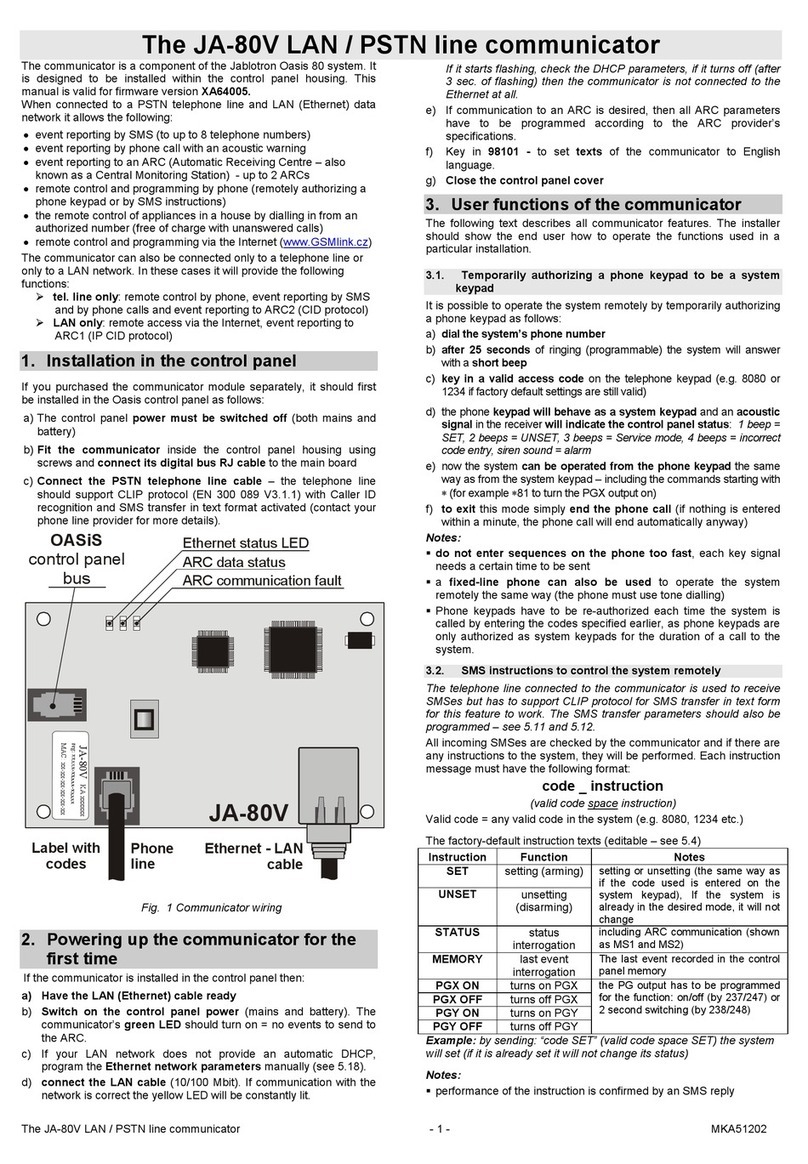
GD-02-DIN Universal GSM communicator and controller
GD-02-DIN Universal GSM communicator and controller 2 / 5 MNP51111
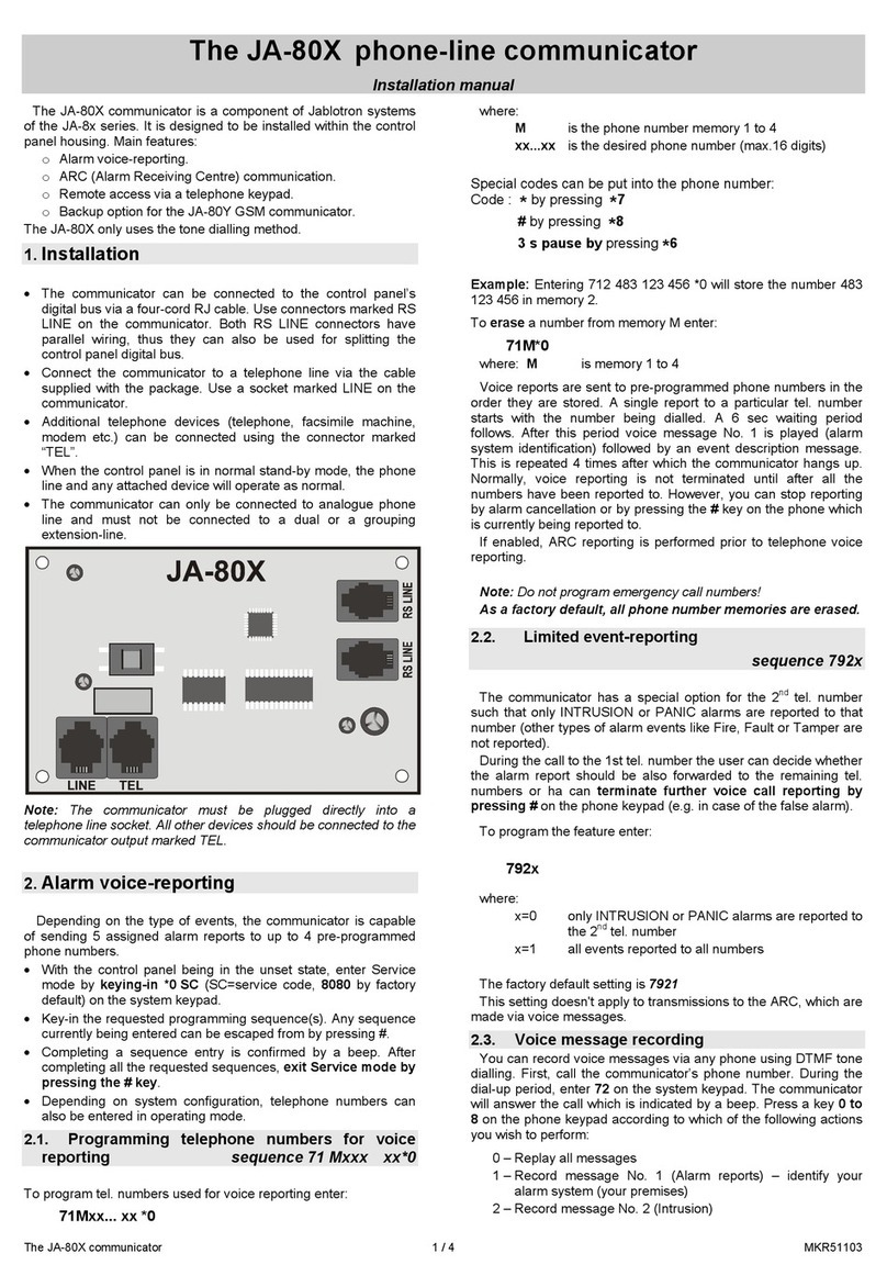
3. Installation and initial setup
The device can only be connected to mains electricity by a person
who has an adequate electrotechnical
qualification. Do not connect the protective earth
conductor. It is necessary to protect the module
externally according to the specification
mentioned in the Technical specifications
chapter. Do not forget to connect the GSM
antenna before you insert the SIM card (turn the device on)!
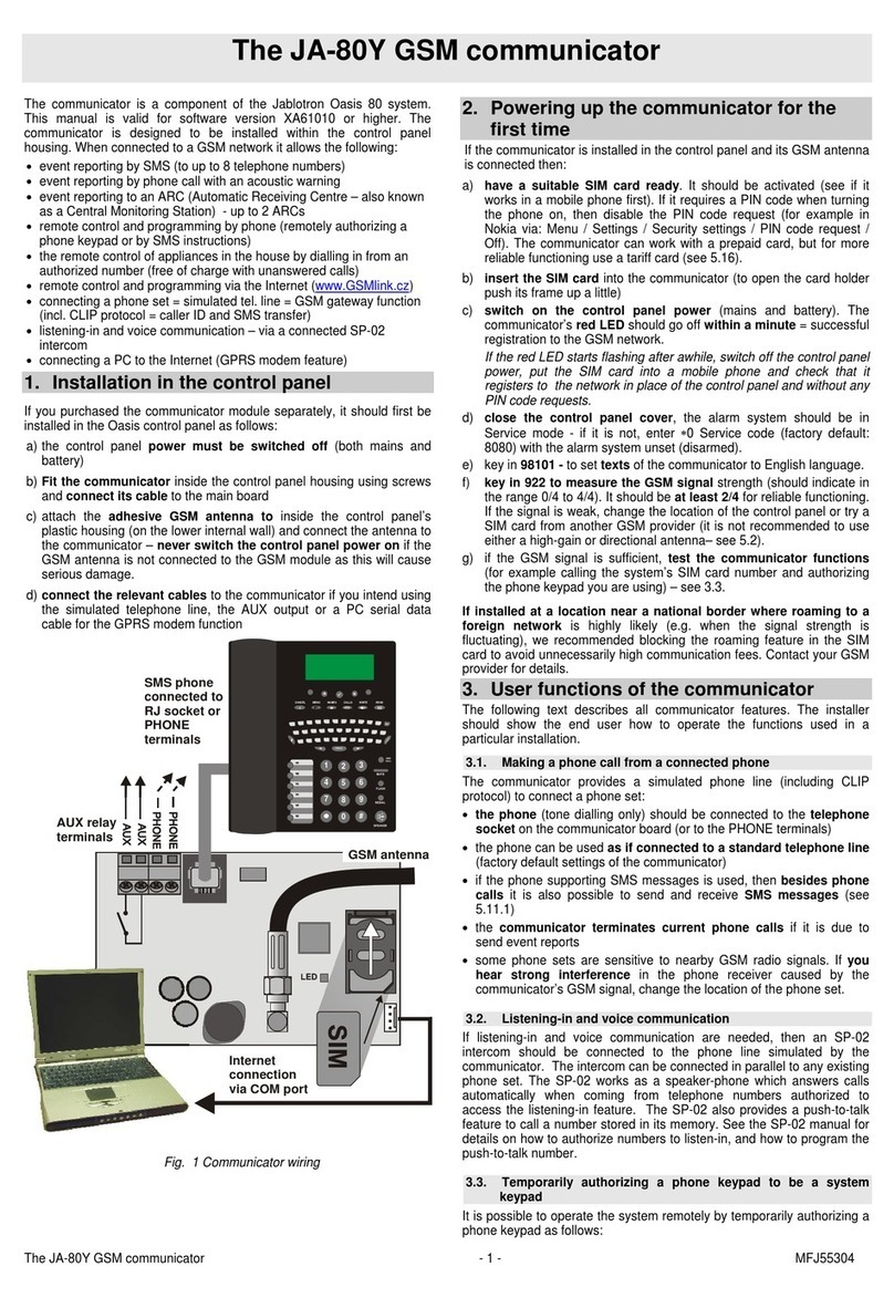
1. Attach the GD-02-DIN onto the required place on the DIN rail.
2. Connect the low voltage part (temperature sensor, inputs and
possibly the REL2 output) of the controller first.
3. Then connect the mains and the REL1 output.
4. Screw on the supplied GSM antenna. If the GSM signal strength at
the installation place is low (less than 40%), we recommend using
an external GSM antenna, for instance type AN-05.
5. By inserting the SIM card the module is turned on. When no SIM
card is inserted, and the device has no mains or internal backup
battery connected – nothing is indicated. When inserting the SIM
card (if the backup battery is not fully discharged) all LED indicators
flash briefly on the GD-02-DIN front panel and then the module
starts to indicate optically all the current statuses mentioned and
described in Table 1.
6. Connect the GD-02-DIN using the supplied MicroUSB cable to the
PC (max. USB cable length with extension can be 5 m).
7. Start the GD-Link software, see chapter 4.
8. Continue with chapter 5 according to the required operation mode.
Recommendations:
For long-term reliable operation it is recommended to use tariffed
SIM cards. Avoid using pre-paid cards which may not work well
when credit balance is low but which also have uncertain SIM card
credit validity periods. If despite this warning you use a pre-paid
card, use the function for automatically checking the credit balance.
This will ensure the periodical checking of credit balance and if
credit is low the module sends you an SMS with a warning sent to
a pre-defined service number (this function must be supported by
your GSM operator).
Use any cell phone to check the SIM card is active by a phone call
or by sending an SMS.
To speed up logging onto the GSM network it is recommended to
disable the PIN code requirement. It can be realized by disabling
the PIN code requirement in the cell phone menu “PIN code
ON/OFF”. If it’s necessary to keep the SIM card protected by a PIN
code (preventing theft), enter a valid PIN code via the GD-Link
software (tab – “Setting” and “SIM card PIN”).
With no SIM card inserted, the device is out of order and it cannot
be used or configured by PC.
4. Configuration via the GD-Link SW
To configure the GD-02-DIN module by computer use
GD-Link software. It serves for reading and changing the device
settings locally connected by USB cable.
The software is free for download from our website
www.jablotron.com, Downloads / Software section.
Follow the instructions of the installation wizard to install the
software successfully. When the installation is done the PC creates
a shortcut for the GD-Link software.
The software requires OS Windows XP or newer.
It is recommended workplace with letters size up to 120 dpi
(standard is 96 dpi).
The software also serves for FW update performance. During
online Internet access the GD-Link SW checks if the FW is really
current and if it detects that a new FW version has been released,
the user is informed and it offers downloading. This file can be used
to perform an FW update by clicking the option “Device / Upgrade
firmware“.
Note: there is an option for checking the current SW version’s
availability and it is possible to enable / disable this in the SW menu
GD-Link / Automatic update.
The GD-Link SW includes eight tabs:
Users – Setup for user telephone numbers, authorisation to control
outputs and report assignment
Inputs – Serves for setting parameters related to inputs,
activation / deactivation texts to be reported. If the input is pre-set to a
Special function (for example Consumption meter), its setting is
inaccessible (all settings can be performed on the selected tab).
Outputs – Serves for setting parameters related to outputs, texts for
control and for reporting switching ON / OFF the outputs. To perform a
test use the “TEST” button. If the output is pre-set to a Special function
(for example Thermostat), its setting is inaccessible (all settings can be
performed on the selected tab).
Thermometer – Serves for the activation and setup of the temperature
monitoring function. Sets up temperature limits, texts send as an SMS
report, etc.
Thermostat – Serves for the activation and sets up the Thermostat
function (temperatures, SMS commands to control REL1 output, etc..).
Consumption meter – Serves for the activation and set-up of the
Consumption meter function (units of a measured utility, the number of
pulses equal to one unit and the default counter state). It also shows
the history of measured values.
Setting – Serves for general settings such as the password for access
to the SW and GSM dialler, SIM card PIN code, max. daily SMS limit or
credit balance checking.
Information – Serves to check the device’s important information
(Reg-Key and production code), current status of inputs, outputs,
temperatures, impulse counter status, number of sent SMSes, credit on
a pre-paid SIM card and GSM data.
Note: The tooltips give you a quick description of programming options.
Move the mouse cursor over the parameter which you want to have
described and the software displays a description.
5. Operation modes
The GD-02-DIN offers the following operating modes:
5.1 CONTROL mode
This operational mode allows you to control the REL1 power
output independently to the REL2 signal output by a pre-defined
SMS text or by dialling in. One more option is using a bridge
between IN1 triggering and REL1. Up to 10 telephone numbers can
be stored in the device to control both outputs independently.
When a password is used outputs can be controlled by any
telephone number not just by the numbers stored in the
device.
Set-up description:
To apply this mode start the GD-Link software and in the
„Users“ tab enter the required telephone numbers in the
„Output control by dialling in / SMS“ column and give them
authorisation to control outputs by SMS or by just dialling in.
The telephone numbers are required to be in international
format.
In the “Outputs” tab you can set “SMS commands to control the
switching ON/OFF” of the both REL outputs or the “way of
switching” (ON/OFF or Impulse) and also the SMS text by
which control is confirmed to the person who is in control.
The current status of outputs is indicated here.
On the „Setting“ tab by the „Output status after power recovery“
parameter (outputs switched OFF or last known status) output
properties can be set for when a mains dropout occurs and
then recovers.
Example: Gate control by dialling in from up to 10 users.
The application requires a contact to be connected to the REL2
output / GND and to the low voltage input of a controlled gate
(Figure 2).
Using the GD-Link software it is necessary to set the telephone
numbers authorised to control the “REL2” output and also to
check (tick) the option by „Output control by dialling in“ on the
„Users“ tab.
