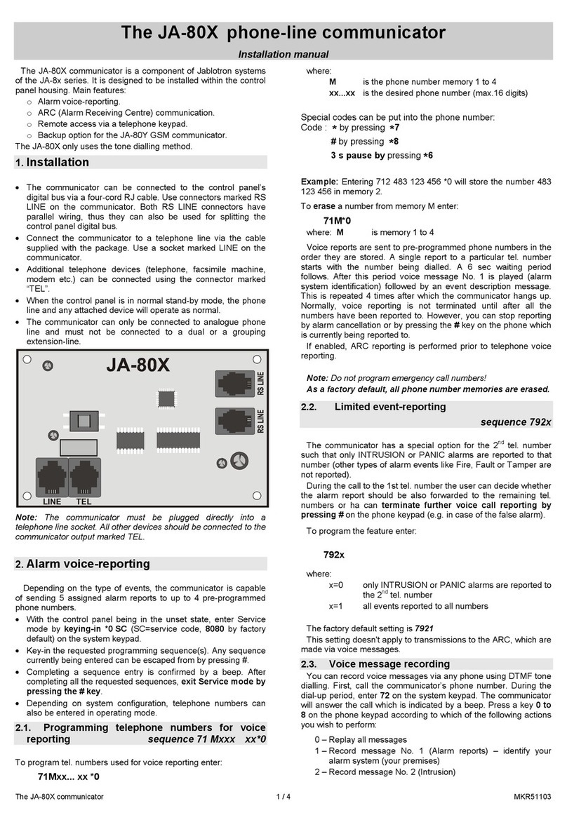
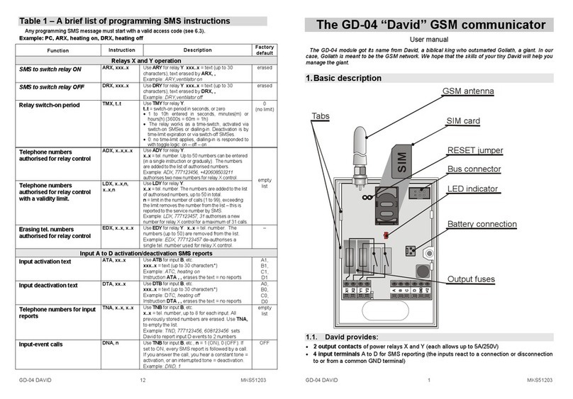
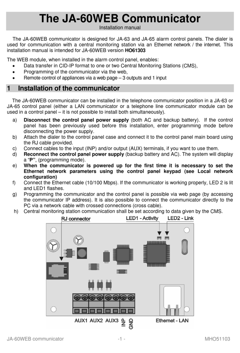
jablotron JA-82Y User guide

TheJA-82YGSMcommunicatorinstallers manual 1/13 MDL51109
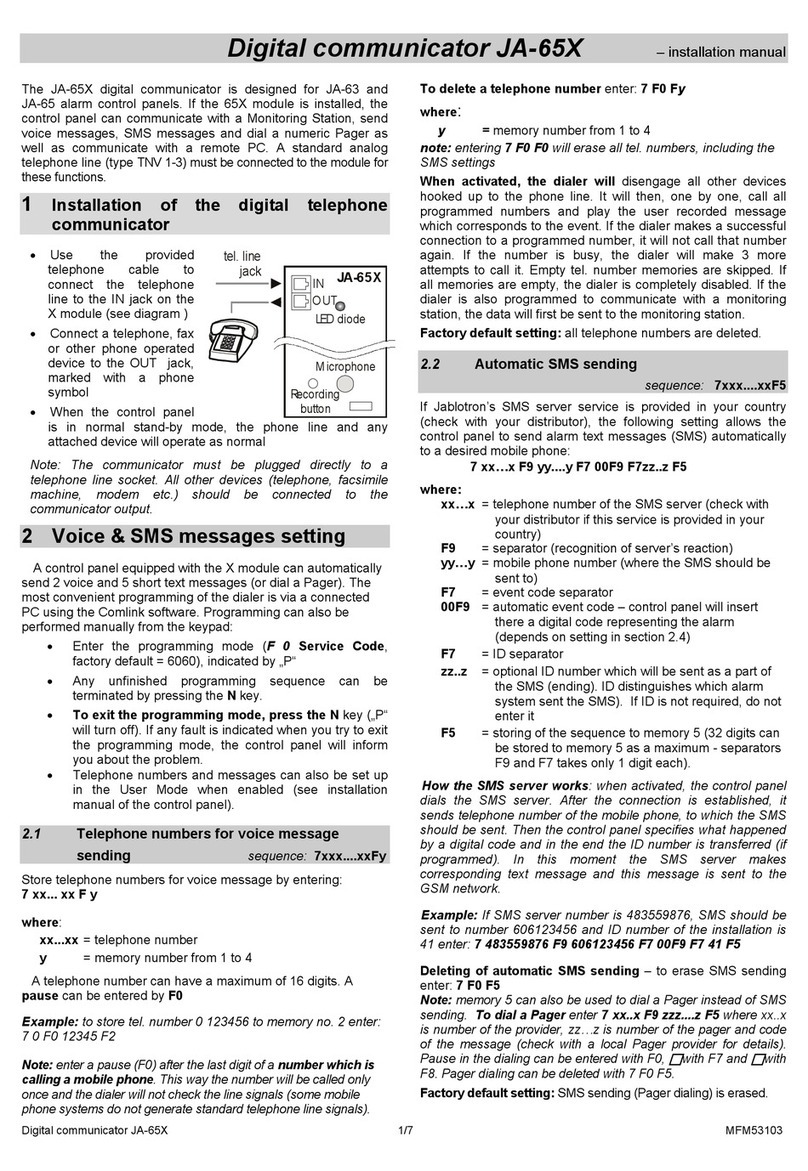
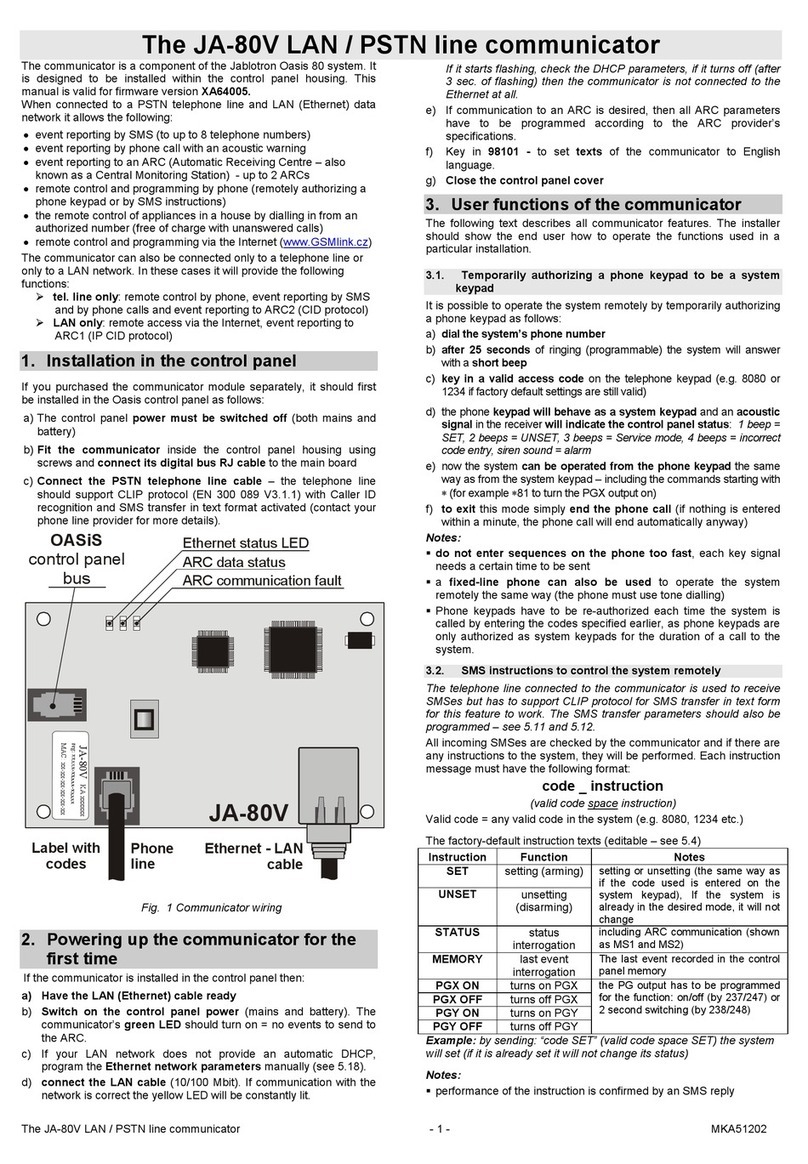
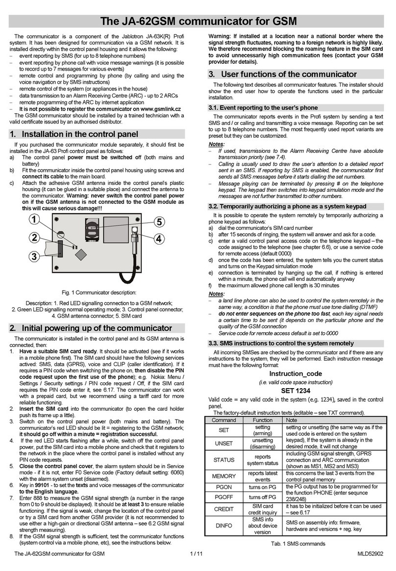
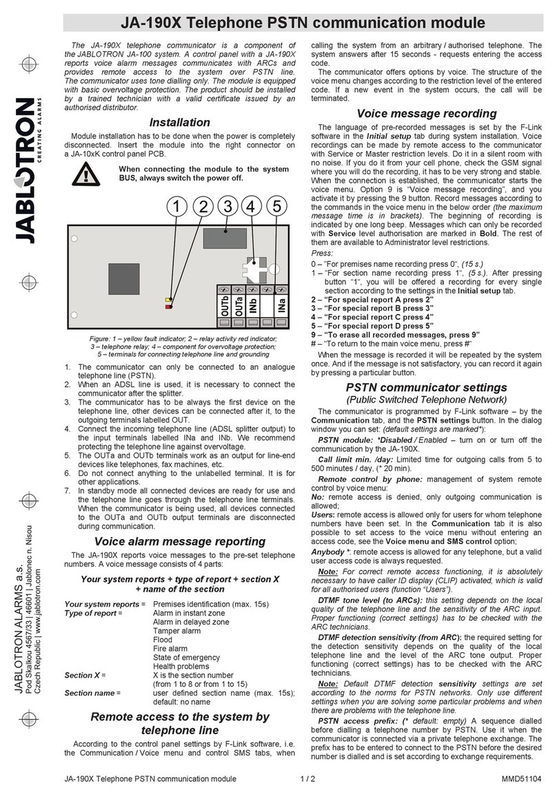
The JA-82Y GSM communicator
The communicator is a component of the Jablotron Oasis 80 system. It has been
designed for communication via a GSM network. It is installed directly within the
OASIScontrolpanelhousing anditallowsthefollowing:
eventreporting bySMS(forupto8telephonenumbers)
event reporting by phonecall with voice message warnings (it is possible to
recordupto7messages forvarious events)
remote control and programming by phone (by calling and using the voice
menu or bySMSinstructions)
remote control of the system (or appliances in the house) by dialling in from
anauthorizednumber(freeofcharge)
remote control and programming of the system via the Internet (It is not
possible to registerthecommunicatoronwww.gsmlink.cz)
datatransmissiontoanAlarmReceivingCentre(ARC)- up to2ARCs
sendingphotosfromJA-84Pdetectorstoa secure server
updating communicatorfirmware, language and newtext sets using OLink
2.0software orhigher
1. Installation in the control panel
If you purchased the communicator module separately, it should first be installed in
theOASiScontrolpanelas follows:
Thecontrolpanelpower must be switchedoff(bothmains andbattery)
Fit the communicator inside the control panel housing using screws and connect
itscabletothemain board.
Attach the adhesive GSM antenna inside the control panel’s plastic housing (it can
be glued in a suitable place) and connect the antenna to the communicator.
Warning: never switch thecontrol panel power on if the GSM antenna is not
connectedto the GSM module as thiswill cause serious damage!!!
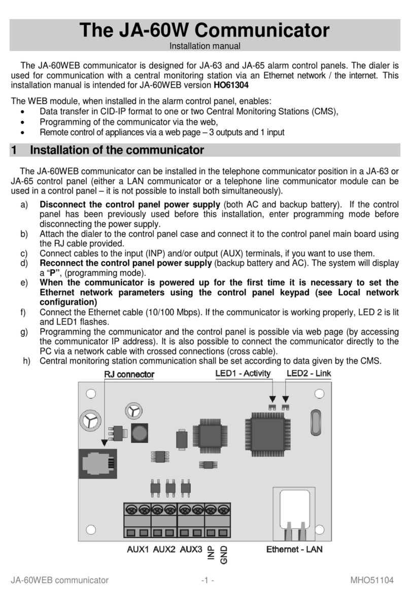
fig. 1 Communicatordescription:
1.LED signalling connection to a GSM network; 2.LED signalling image
transmission; 3. control panel connector; 4. GSM connector; 5. SIM card
2. Initial powering up of the communicator
1. The communicator is installed in the control panel and its GSM
antennaisconnected,then:
2. Have a suitable SIM card ready. It should be activated (see if it works
in a mobile phone first). If it requires a PIN code when switching the
phone on, then disable the PIN code request upon the first use of
the phone); e.g. Nokia: Menu/ Settings / Security settings / PIN code
request / Off. The communicator can work with a prepaid card, but we
recommendusingatariff cardformore reliablefunctioning
3. Insert the SIM card into the communicator (to open the card holder
pushitsframeupalittle)
4. Switch on the control panel power (both mains and battery). The
communicator’s red LED should be lit = registering to the GSM
network; it should go offwithina minute= registrationsuccessful
5. If the red LED starts flashing after a while, switch off the control panel
power, put the SIM card intoa mobile phone and check that it registers
to the network in the place where the control panel is installed without
anyPINcode requests
6. Closethecontrol panel cover,the alarmsystemshould beinService
mode - if it is not, enter *0 Service code (Factory default setting: 8080)
withthe alarmsystemunset(disarmed)
7. Key in 99101 - to set the texts and voice messages of the
communicatorto the English language
8. Key in888tomeasuretheGSM signalstrength(anumberintherange
from 1/4 to 4/4 should be displayed). It should be at least 2/4 to ensure
reliable functioning. If the signal is weak, change the location of the
control panel or try a SIM card from another GSM provider (it is not
recommended to use either a high-gain or directional GSM antenna –
see6.2GSM signalstrengthmeasuring)
9. If the GSM signal strength is sufficient, test the communicator functions
(system controlvia amobile phone,etc), see theinstructions below
Warning: If installed at a location near a national border where the signal
strength fluctuates, roaming to a foreign network is highly likely. We
therefore recommend blocking the roaming feature in the SIM card to avoid
unnecessarily high communication fees (contact your GSM provider for
details).
3. User functions of the communicator
The following text describes all communicator features. The installer should show
theenduser howtooperatethe functionsusedinthe particularinstallation.
3.1. Event reporting to the user’s phone
The communicator reports events in the OASiS system by sending a text SMS
and /or calling and transmitting a voice message. Reporting can be set to up to 8
telephone numbers. The most frequently used report variants are preset but they
canbecustomized
Notes:
If used, transmissions to the Alarm Receiving Centre have absolute
transmissionpriority(see7.4).
Calling is usually used to draw the user’s attention to a detailed report sent in
an SMS. If reporting by SMS is enabled, the communicator first sends all SMS
messages before it starts diallingtheset numbers.
Message playing can be terminated by pressing * on the telephone keypad.
The keypad thenswitches into keypadsimulation mode and the messages are
not further transmittedtoothernumbers.
3.2. Temporarily authorizinga phone as a system keypad
It is possible to operate the system remotely by temporarily authorizing a phone
keypadasfollows:
Dial the communicator’s SIM card number.
After 15 seconds of ringing, the system will answer with a voice menu welcome
messageandaskforacode.
Key in a valid control panel access code on the telephone keypad –the master
code (default 1234), ausercodeor possiblythe servicecode(default8080).
Once the code has been entered, the voice menu offers the basic system functions
(see10).
To exit this mode simply end the phone call. If nothing is entered within a minute,
thephonecall will endautomatically anyway.
Themaximum allowedphonecalllength is30minutes.
Notes:
a fixed-line phone can also be used to operate the system remotely in the
sameway.The phone mustusetonedialling (DTMF).
do not enter sequences on the phone too fast, each key signal needs a
certain time to be sent (it depends on the particular phone and the quality of the
GSM connection
3.3. SMS instructions to control the system remotely
All incoming SMSes are checked by the communicator and if there are any
instructions to the system, they will be performed. Each instruction message must
havethefollowingformat::
code_instruction
(i.e.validcodespaceinstruction)
Valid code = any valid code in the system (e.g. 8080, 1234)
Thefactory-defaultinstructiontexts(editable–seeTXTcommand)
Command
Function
Note
SET
setting(arming)
setting or unsetting (thesamewayasifthe
used codeis entered onthesystemkeypad),
If thesystemis alreadyinthedesiredmode,
it willnot change
UNSET
unsetting
(disarming)
STATUS
reportssystem
status
includingGSM signalstrength, GPRS
connection and ARCcommunication(shown
as MS1,MS2and MS3)
MEMORY
reportslatest
events
this concerns thelast 3eventsfromthe
controlpanel memory
PGXON
turnsonPGX
thePGoutputhasto be programmed forthe
function:on/off(by237/247) or 2second
switching(by238/248)
PGXOFF
turnsoffPGX
PGYON
turnsonPGY
PGYOFF
turnsoffPGY
CREDIT
SIMcard credit
inquiry
ithastobeinitializedbeforeit canbeused–
see6.21
DINFO
SMSinfoabout
deviceversion
SMSonassembly, firmware,andhardware
versions,reg.key, remoteaccess codevia
OLink
Tab. 1 SMS commands
Example by sending: “code SET” (valid code space SET) the system will set (if it is
alreadysetit willnotchangeitsstatus)
Notes:
the system will confirm performance of the SMS instruction by an SMS reply, if
this functionisallowed
the SMS instruction texts are not case-sensitive and only ASCII characters are
allowed
theSMSinstructiontextscancontainmultipleinstructionsseparatedwithacomma
if you are sending an instruction and you are not sure whether any other text
will be automatically added to the SMS (for example, when using an SMS
internet gate)typetheinstructionas: %codeinstruction%%
thevalid codecan alsobeenteredautomatically,see6.6.

TheJA-82YGSMcommunicatorinstallersmanual 2/13 MDL51109
3.4. Remote control by unanswered calls
A limited number of system functions can be activated remotely by calling the
system from pre-authorized phones. It is possible to pre-authorize phone numbers
stored in memories M1 to M8 (also used for event reporting –see 4.1). To pre-
authorize a telephone number insert at the end of the number and follow it by a
single digit(1,2, 3, 8 or 9)–seethenotesinsection 4.1. If such anumber calls,the
communicator enters a “digit“ sequence in the system after the first ring (as if it
had been entered manually on the system keypad). This remote control by
unansweredcallsenablesthefollowingfunctions:
1settingthecompletesystem(identicaltoABCbutton)
2Asectionsetting(identicalto A button)*
3AandB or justBsectionsetting (identicaltoBbutton)*
8PGX turns on for 2 sec (if PGX is programmed for the 2s pulse
function)
9PGY turns on for 2 sec (if PGY is programmed for the 2s pulse
function)
Notes:
if a phone sends no caller identification datait cannot be used for thistype
of remotecontrol by phone
when using remote control by unanswered calls, and if the sequence 85 M0
has been entered, the communicator terminates the call itself, so that remote
controlisfreeof charge
a phone which is pre-authorized for remote control by unanswered calls can
also temporarily authorize its keypad to fully operatethe system (see 3.2) –just
canceltheactioncontrolledbyanunansweredcall
if it is desired that the phone which is authorized for toll-free remote control
should not receive event reports, then turn the reports off for that tel. number
(see 6.3)
the*Xfunctionsmustbeenabled in thecontrolpanel
inserting *X is used when programming a function using a keypad, the OLink
softwarehas aspecialsectionforthis
4. User communicator programming
User setting of the communicator is performed by entering sequences from the
OASiS system keypad. Selected parameters can also be controlled or set by SMS
instructionsorviaOLink.
Settingonthesystem keypadis possible onlyinthecase thatthecontrolpanel isin
maintenance mode (if it is not, enter *0 master code –Factory default setting
1234). Modification of values set in the communicator is performed by entering
programmablesequences(see Tab. 7).
Press the # button to exit Maintenance mode or to cancel code entering when
youkeyin a wrongnumber.
If setting of telephone numbers in Maintenance mode is enabled in the control
panelsettings (sequence 251of the OASiScontrol panel), then it is possible to set
the following communicator parameters in Maintenance mode by keying in the
belowmentionedsequencesbeginning with8:
Set telephonenumbersM1toM7
Assign codes for control by SMSes withouthaving to enter thecode
Select events whichshouldbe reported by an SMSmessage and calling
Enable/ disable remoteaccess (fullaccessorsinglenumbers)
MeasureGSMsignalstrength
Limitthenumber of sentSMSes
Set forwardingofincomingSMSestothefirst settelephonenumber
RestarttheGSMcommunicator
Recordvoicemessages
Changeremoteaccesscode
4.1. Setting of telephone numbers for reporting
The communicatorreportseventsin the OASiS system bysendingatext SMSand
/ or calling and transmitting a voice message. Reporting can be programmed for
toupto8telephonenumbers.
The most frequently desired reports are already assigned to the telephone number
memories by factory-default, so you only need to program tel. numbers to the
particularmemories:
Overviewofreports assigned totel.numbers (thiscan bemodifiedsee6.4)
M
Reports
0
Communicator´s own SIM card number
1
AlarmsbySMSandphonecall, faultsbySMS (ABC)
Poplachy SMS zprávou
Technické zprávy odesláním SMS (pro servisního technika)
2
AlarmsbySMSandphonecall(AC)
3
AlarmsbySMSandphonecall(AC)
4
AlarmsbySMS(AC)
5
AlarmsbySMSandphonecall(BC)
6
AlarmsbySMSandphonecall(BC)
7
AlarmsbySMS(BC)
8
TechnicalfaultsbySMS(foraservicetechnician)(ABC)
tab. 2 Reports assignedtotelephone number memories M1to M8
To program phone numbers to the M memories, enter the following sequence
whilein Maintenance/ Servicemode:
81 M xxx...xy 0
where: Mismemorynumber 1to8
xxx...x isatelephonenumber(max.20digits)
yisasequenceforcontrol viaunansweredcalls
(it doesnot havetobeentered)
In a split system, information from all sections (ABC) is reported to the 1st
and8th number positions, sections AC to numbers 2 to 4, and from sections
BC to positions 5 to 7, showninOLink software bycolour differences
Notes:
In a split system, when you change a detectors section, adjust the reaction of
the detector etc, you have to enter enrollment mode for 1s and leave it before
youleaveservice mode.Thiswaythe changes aresavedinthecommunicator.
For automatic time synchronizing by SMS use position 0 in the telephone
number settings (the position for its own SIM card number). When you change
theSIM cardthisnumberwill beautomaticallyerased.
ToeraseanumberfrommemoryM enter: 81 M 0
Example 1: entering 81 5 777 777 777 0will store the number 777777777 in
memory M5 (alarms will be reported by SMSes + phone calls with a voice
message) Setting/Unsetting will only be reported by an SMS). Remote access is
allowedforthis telephone number.
Example 2: entering 811 777 777 777 8 0will store the number 777777777 in
memory M1 (alarms will be reported by SMSes only.) Calling from this number will
turn onPgXfor2s.Remoteaccessisnotallowedtothistelephonenumber.
Notes:
Entering *9 before the first digit will insert a “+” for the international formatting of
phonenumbers
SMSreport text consistsof the installation name, event type, name of the event
source, date and time. For example: „Report from your alarm: setting 47:
device Time 11:27 01.08 ”
if other events or texts should be reported to a particular number, change the
communicator settings (see 6.4, 6.7 and tab. 5 the list of events which can be
reported to your phone and their factory defaultsettings)
5. Voice menu for control via a telephone
The communicator is equipped with a voice menu for remote control of the basic
system functions (remote access viaa telephone mustbeenabled). The menu has
factory default voice reports in multiple languages –the desire languages selected
by keying in the 991 xxsequence (see 6.1). Thevoicemenu function (Fig. 2Voice
menu scheme)is as follows:
after 15 seconds of ringing the communicator will answer with a voice
menu welcomemessage.
After entering valid code the voice menu offers setting or unsetting. The
offer is played once and if you press anykey, the current status is reported
andthe current offer replayed.
If you press 9 in the menu, you will hear: “Keypad simulation“ and the
telephone will start acting as a system keypad. It will remain in this mode
making itpossibletoenter sequences whichare confirmed bybeeping.
When you enter the service / maintenance code verification is performed
and if the code is valid, you will hear: “Service mode, keypad simulation“. It
remains in this mode and you can enter keys which are confirmed by
beeping. If you key in 892 now, you will enter voice message recording
menu –see10.
Events happeningduringremote accessare reportedonceevery5 secs
6. Installation programming
The most convenient and complete programming is best done by a PC running
OLink softwareconnectedlocallyinthe installationorremotelyviatheInternet.
The communicator can also be programmed by keying in sequences from the
OASiSsystemkeypadorviaSMSprogramminginstructions.
Programming by the system keypad is possible only if the control panel is in
Service mode, if it is not, key in *0 Service code (factory default setting: 8080) with
the alarm system unset (disarmed) The setting is performed by keying in
programming sequences, (see Tab. 7 communicator programming sequences).
Press the # button to exit service mode or to cancel code entering when you
keyina wrong number.
6.1. Communicator language setting
The language of the texts and voice menu used by the communicator can be set
bytheinstruction:
991 xx
where:xx isa numberdefiningthelanguage–seethefollowinglist:
0
1
E
N
English
1
0
FI
Finish
0
2
CZ
Czech
1
1
N
O
Norwegian
0
3
SK
Slovak
1
2
SV
Swedish
0
4
NL
Dutch
1
3
FR
French
0
5
D
E
German
1
4
HU
Hungarian
0
6
PL
Polish
1
5
RU
Russian

TheJA-82YGSMcommunicatorinstallersmanual 3/13 MDL51109
0
7
D
A
Dannish
1
6
TR
Turkish
0
8
IT
Italian
1
7
ES
Spanish
0
9
PT
Portuguese
1
8
EL
Greek
Example: Keying in 99101 will set English.
Notes:
keying in 00 will reset the texts and voice messages to the factory default
valuesinthe currentlyset language.
Set the language before editing the text in the system (a change of language
willchange the text to the factory default setting)
A change of languageinthe communicator willautomatically result inchanging
thelanguage intheconnectedkeypads
Thesetlanguage willnotchangewhen aresetisperformed
Factory default setting: 99101= English
6.2. GSM signal strength measuring
A good quality GSM signal is necessary for the reliable functioning of the
communicator. Keying in 888 starts GSM signal strength measuring. The keypad
then displays the signal strength in the range 1/4 to 4/4 and the measuring is
repeated every second –new data is indicated bya beep. This mode allows users
to find a suitable location for the communicator antenna. Press the # key to exit
the measuring.
The signal should be at least 2/4. In places with a weak signal we recommend
tryinganother GSMprovider’s SIM card.
Warning: it is not recommended to use a directional GSM antenna with the
communicator (the module would thus communicate with a single cellular
base station only). The communicator normally communicates with at least
three cellular base stations (the connection is thus more stable). It is not
even recommended to use a high-gain antenna –if the signal is transmitted
over a distance exceeding 30km, it does not ensure standard GSM function
due to time lapses in the transmission.
6.3. Setting of telephone numbers and events
The factory-default list of reported events and their assignment to telephone
numbersM1toM8(tab.1)canbemodified.
The complete list of reportable events is shown in ( tab. 5 List of events which can
bereportedtoyourphoneandtheirfactory defaultsettings).
It is possible to select whether the event should be reported by an SMS or by a
phonecall, or in both ways.
Each event has pre-programmed factory-default SMS text (it can be modified –
see6.8).
6.4. SMS report setting
Toseteventstobeing reportedbySMS,enter:
82 M uu x
where:
M is phone number memory1 to 8
uu eventcode01to97(seetab.5)
x 0=noSMSreport, 1=SMSreport
Example: If 82 8 03 1 is programmed anda fire alarm is triggered (event 03 in the
table),it willbereportedbySMStothephonenumber stored in memoryM8.
6.5. Voice message setting
Toseteventstobeing reportedbyvoicemessages,enter:
83 M uu x
where: Misphonenumbermemory1to8
uu eventcode01to97 (seetab.5)
x0=nophonecall,1=call
Example: if 83 1 03 1 is programmed and a fire alarm is triggered (event 03 in the
table), the communicator will phone the first number stored in the memory and it
willkeep repeating:Yoursystem isreportingafirealarm.
Notes:
Calling is usually used to draw the user’s attention to a detailed report sent in
an SMS. If reporting by SMS is enabled, the communicator first sends all SMS
messagesbeforeitstarts dialling.
If used, transmissions to the Alarm Receiving Centre have absolute
transmissionpriority(see7.4).
The message playing can be terminated by pressing # on the telephone
keypad. The keypad then switches into keypad simulation mode and the
messagesarenotfurthertransmittedtoother numbers.
6.6.Access code assignment to programmed telephone
numbers
If you do not wish to enteryouraccess code eachtime yousend anSMSmessage
with an instruction, you can assign an access code which will be inserted into the
SMS automatically by the communicator to the selected telephone number. To do
so,keyin:
84 M xxxx
where: Misphonenumbermemory1to8
xxxx Valid code UC/ MC/ SC
Example: if 83 1 2222 is programmed, the code 2222 will be automatically
inserted in an SMS with instructions sent from the first number stored in the
memory
Factory default setting: No code
6.7. Allowing remote access for telephone numbers
Remote access is allowed for numbers saved in positions 1 to 8. Programming
sequence:
85 M x
where: Mmemoryposition tel.numbers1to8
xparameter1to allowaccess
parameter 0to denyaccess
Factory default settings : remote accessallowed for all numbersin
positions 1 to 8
6.8. SMS and instruction text editing
The communicator contains various factory default text strings which are used to
create SMS reports and also SMS instruction texts. The language of the text can
be set –see 6.1. These text strings cannot be changed from the system keypad
but they can be edited by OLink software (either locally or remotely via the
Internet), orbysendingthefollowingSMSinstruction:
code_TXT_n,text,n,text,......n,text
where: Code isavalidservicecode(Factorydefaultsetting8080)
_space
TXT is aninstructiontoedittexts
Ntextnumber(0to611, seetab. 6)
,comma(or fullstop)
text thenewtext (max. 30characters) which will replace theformer text.Itis
invalidtoentera commaorafull stop insidethe text string, but a space
isvalid withinthetext string(spaces outsidethe textstring areignored).
Notes:
A single SMS TXT instruction can modify multiple texts (limited only by the
maximumlengthofasingleSMS)
the communicator is not case-sensitive and it is recommended to use only
English ASCII characters (some networks do not support non-English national
characters)
the communicator creates SMS reports with 5 parts (installation name, event
description, source number (code or device 01 to 50), source name and time.
The maximum possible length of an ASCII SMS is 160 characters (only 70
characters for national characters) If this length is exceeded, the report is sent
asmultipleSMSes.
Thecommunicatorautomaticallyfillsinspaces, delimitersandtime.
Examples:
ifthe factory defaultservicecodeis8080thentheSMSinstruction:
8080 TXT 20,key fob Bob,21,Key fob Jane changes the description (name) of
thekeyfobs enrolledtoaddresses20and21.
8080 TXT 605,heating on,606,heating off edits the text of the two instructions
used to command the heating to be switched on and off by the PGX output (the
PGXoutputmustbeprogrammedtohaveanON/OFFfunction).
6.9. Voice message recording
Recording message is done by phone with the system in service mode. Dial the
system SIM card number. When the system answers, enter your access code,
then press 9 (keypad simulation) and enter *0 service code or *0 Master code
(unless you are in service / maintenance mode) and then sequence 892. The
communicator will report that you are in voice message recording mode. You will
hear regular beeping from the receiver; the communicator is waiting for a keyto be
pressed:
0–replayallmessages
1–Recordmessageno.1(intruderalarm)
2–Recordmessageno.2(firealarm)
3–Recordmessageno.3(tamper alarm)
4–Recordmessageno.4(panicalarm)
5–Recordmessageno.5(faultalarm)
6–Recordmessageno.6(alarmreport)–installationidentification
7–Recordmessageno.7(other event)
8–deletealluser recordings=resettofactorydefaultrecordings
When you press a key from 1 to 7, you will hear another beep and you can start
speaking. The end of recording is signalled with a beep and the message is
replayed. The communicator then returns to the main menu (regular beeping) and
it is possible to record further messages. The length of message no.6 should not
exceed 5s, other messages should be 3s long. Press # to stop the voice recording
menu and return to service / maintenance mode.
Message no.7 is played upon each event which you set for a voice message and
which is not an alarm. The factory default message is: Other event. i.e. is usually
used to inform about sending SMS. However, it can also be used specifically for a
particular event (e.g. it may be used to report PG output control, etc. –it depends
onthe83Muu xsettings see6.5)
TheJA-82YGSMcommunicatorinstallersmanual 4/13 MDL51109
Notes:
Listeningtothemessagecanbeterminatedby pressingthe* key.
To exit the message recording mode, just end the call.
The messagesare recorded ina memory which is noterasedwhenthesystem
powersupply is shut down.
For events like setting / unsetting, the voice messages “Armed system” ,
“Disarmed system” or “Partially armed” are reported; these messages
cannotbechanged.
6.10. Quick enabling / disabling of reporting to phones
Eventreportstoyourphonecan beenabled/disabledasfollows:
901 0 allSMSandcallreportsdisabled
9011 allSMSand callreportsenabled
901 2 all reports enabled except reports of setting and unsetting by
users 41 to 50 (i.e. their codes, cards and key fobs). Master code
control is not reported either. This allows setting and unsetting done by
reportrecipients(owners,bosses,etc.)not tobereported.
Factory default setting: 9011 allreportsenabled
6.11. Enabling remote access
The following sequence enables remote access to the system by phone or
Internet:
802 0 remoteaccesscompletelydisabled
802 1 access fromanytelephone and Internet access via OLinkenabled
802 2 access from programmed phones and Internet access via OLink
enabled
Factory default setting: Remoteaccess enabled
6.12. Forwarding ofincoming SMS messages
The communicator enables the automatic forwarding of incoming SMS messages
whichcontain novalidinstructions tothesystem:
801 0 messages are not forwarded, but the communicator saves the last
10receivedmessagestothe SIMcard
801 1 messages are forwarded to the first programmed tel. number in
memories M1 to M8 (e.g. if numbers are only programmed in M5
and M6, then messages will be forwarded to M5). The tel. number
from whichthe SMS was received will be shown at the beginning of the
forwardedtext.
Factory default setting: messagesareforwarded
Note:
In order to protect the user against runaway (donation SMSes etc.), the
forwarding is limited to the first 50 SMS messages. The counter can be erased
automatically each midnight, by processing any SMS instruction or by exiting
Service/Maintenancemode.
6.13. Automatic GPRS configuration
If the communicator detects a SIM card change andthe main power is on, it sends
an SMS to the YTUN Jablotron server with the network identification. The server
sendsback: APN,login, password andownSIMcardtelephonenumber.
903 0 autoconfiguration disabled
903 1 autoconfiguration enabled
Factory default setting: autoconfigurationenabled
6.14. SMS instruction confirmation
If the communicator receives a valid SMS instruction, a confirmation SMS will be
sent a s areply.Thisconfirmationcanbedisabled asfollows:
904 0 disabled
904 1 enabled
Factory default setting: enabled
6.15. Reaction to incoming calls
This sequence can be used to set the communicator’s reaction to incoming phone
calls:
905 0 the communicatorignoresincoming calls
905 1 the communicatorwill answerafterringingfor 15s
Factory default setting: answer after ringing for 15s
6.16. GSM signal dropout indication
This feature enables the monitoring of GSM network signal availability. If enabled
and if there is a GSM signal dropout longer than 15 minutes, the control panel
announces “External communication fault”.
906 0 signalavailabilitymonitoringdisabled
906 1 signalavailabilitymonitoringenabled
Factory default setting: disabled
6.17. Time synchronization via SMS
This setting enables the function for synchronizing the clock in the control panel.
Seechapter8.5for further details.
907 0 synchronizationoff
907 1 synchronizationon
Factory default settings: on
6.18. Phone receiver loudness
To set the loudness of the receiver of the phone which is used to call the
communicatorkeyin:
909 x wherex is anumberfrom 1to9(max.)
Factory default setting: 9 (max.)
6.19. Number to be called to maintain SIM card validity
If a prepaid SIM card is used and a lackof outgoing phone calls for a certain period
cancels the validity of the SIM card, then this function offers the following: if there
have been no outgoing phone calls within the last 90 days, then the communicator
automatically calls the number programmed by this sequence. The communicator
waitsuntilthecallisansweredand then automaticallyhangsupafter10sec.
910 xx...x 0
where: xx...x isthetelephone number
Notes:
Toerasethis numberenter910*0
It is recommended to call cheap public services (e.g. weather forecasts etc.)
but not toll-freenumbers.
Factory default setting: Erased
6.20. Restriction of thenumber of sent SMSes
The parameter limits the amount of sent SMSes to 100 per 24 hours. 50 may be
alarm SMSes and 50 maybe for other events. This is to prevent enormouslyhigh
telephonefees.
803 0 restrictiondisabled
803 1 restrictionenabled
Factory default setting: enabled
6.21. Prepaid SIM card credit interrogation
The communicator is capable of checking the credit balance of its SIM card upon
request (by “CREDIT” SMS instruction) or this activity can be requested
automatically (with a preset cycle) and if it finds out that the remaining credit is
lower than the preset value, an information SMS is sent. The function is set by
sendingthefollowing SMSinstruction:
code_CREDIT_uu..u_xx_yyy_zz
where:
Code validaccessorservicesystemcode(e.g. 8080 or1234),the changeof
parameters is possible on with a service code (other codes allow SMS credit
interrogation “1234 CREDIT“)
_space
uu..u instructionrecognizedbytheGSMnetwork tocheckthe balance
xx automaticcheckingperiodindays,
yyy minimumacceptablecreditbalance
zz the textual position in which the number showing the balance starts in
thereplymessagefromtheGSM provider.
Notes:
If the reported credit balance is lower than theset limit (yyy), text no. 545 will be
sent to phone numbers M1andM8 which have the “Low credit balance” (event
no. 50) eventsendingenabled
If only uu..u follows the CREDIT instruction (no xx yyy zz) thenperiodic balance
checkingwillnotbeperformed,butthebalancewillbechecked immediately
If there is further data following the CREDIT instruction, the communicator will
memorize them and automatically put them in the message when the CREDIT
instruction is used again (i.e. the Credit instruction must contain at least the
uu..u part upon the first sending) and the user just needs to send: code
CREDIT
Example: sending the SMS instruction “code CREDIT
101# 7 50 1” causes the
credit balance to be checked every 7th day after the SMS has been sent and if the
balance (starting with the first character in the message from the GSM provider) is
lowerthan 50 currencyunits it will be reported.
Warning: the use of prepaid SIM cards in the communicator can negatively
influence the reliability of the device. Some GSM providers block cards not
only when there is no credit but also when they are not topped up frequently
enough. This means that even if there is enough credit balance on the card,
the communication can still be blocked. We therefore strongly advise the
use of tariff SIM cards !!!
6.22. Remote programming by SMS instructions
The communicator enables remote programming of the system by the following
SMSinstruction:
code_PRG_seq_seq, another instruction
where:
Code validaccessorservicesystemcode(e.g. 8080or 1234)
_space
seq programmingsequenceusuallysetviathekeypad
Notes:

TheJA-82YGSMcommunicatorinstallersmanual 5/13 MDL51109
Only characters which can be keyed in from the system keypad (0 to 9, * and
#)canbeusedinthesequences
When a valid instruction is received, the communicator performs the sequence
by simulating entering the keys on the keypad. A comma in the SMS is taken
asapauseinthesequenceentering.
If you want to remotely reprogram the system it must first be unset and then
switchedtoprogrammingmode
The number of sequences in one SMS is limited by the maximum size of the
SMSintheGSMnetwork.
Example: by sending SMS 8080_PRG_08080_201_# the exit delay will be set
to10s
6.23. Registration code
You need to know the communicator registration code when first connecting via
the OLink software through the Internet. The code is stated on the label on the
communicator panel but it can also be sent to the mobile phone by SMS. To
request aregistrationcode,enter:
911 xx...x0
wherexx...x is thenumberofthe phone where thecodeshouldbesent
Notes:
The time needed for delivery of the code depends on the current GSM network
speed
Each communicator has a unique registration code in the following format:
xxxxx-xxxxx-xxxx
6.24. Remote access password
This security key for data communication is a condition for remote access to the
systemviaOLinkprogram.It isset through thefollowingsequence:
894 xxx …x 0
where:
xxx…x is asecurityaccess password which can have1 to32digits
Note:Ifa passwordusing letters is required, it mustbe set in the OLinksoftware or
byanSMSmessage.Lettersarecase-sensitive.
Factory default setting: 1234ABCD
6.25. Restarting GSM communication
After893 has been entered, thecommunicatordisconnects from the GSM network
and then re-registers itself. This re-registrationdoes not change any settings in the
communicator. It should be used after GSM network faults or data collisions and in
some networks it also has to be used after a blocked SIM card has been
unblocked by the GSM provider. It is also possible (if the SIM card canstillreceive)
totriggerGSMnetwork re-registrationbysendingtheSMSinstruction:
code GSM
6.26. Communicator reset
Entering 998080 returns the communicator to its factory default settings.
Telephone numbers will be erased together with all untransmitted reports but the
text settings inthecommunicator willnot be changed.
6.27. SIM card’s PIN code
It is recommended to use a SIM card with disabled PIN protection in the
communicator. If you still want to use a card with PIN protection, enter the PIN by
entering the following sequence (it must be entered after the control panel has
been poweredup):
920 PIN0
Example:IftheSIMcardPINcodeis1234,enter92012340
Notes:
If the communicator does not register to the GSM network within 1 minute of
the PIN being entered (this problem is shown by the red LED flashing), then
youeitherenteredawrongPINortheGSM signalis tooweak.Insucha case:
enter 920*0 while in control panel service mode (erases the PINentered in the
communicator)
disconnectthecontrol panelpower(mains andbattery)
take out the SIM card, insert it into a mobile phone and check whether the PIN
is correct. Check whether the signal strengthat the location of the control panel
issufficient
if you know the right PIN code and the GSM signal is strong enough, put the
SIMcard back into thecommunicator, turn on the control panel power andthen
enter the correct PIN code (920 PIN *0) and wait until the communicator
registers to the GSM network (its red LEDshould turn off within aminute)
The communicator memorizes the set PIN and it will use it automatically
wheneveritregisterstotheGSM networkagain.
If youarereplacingthe SIMcard inthe communicator with another oneandthe
former one used a PIN code, first switch the control panel to service mode and
enter 920*0toerasetheformerPINcode. TheSIMcardcan thenbechanged.
Warning:ThePINcodecannot be changed if theARCsettings arelocked
Factory default setting: The PIN code iserased
6.28. GPRS parameter setting
GPRS data communication (wireless Internet via a GSM network) is used for
remote access via the OLink software and also for communication between the
system and the ARC. To use GPRS data communication it must first be enabled
(activated) in the SIM card (contact your GSM provider for details). Depending on
the SIM card used, the GPRS parameters (APN and possibly the login and
password if the SIM card requires them) must be programmed by sending the
followingSMSinstructiontothecommunicator.
code_GPRS_ x..x_y..y_z..z
where:
Code validservicesystemcode (e.g. 8080)
_space
x..x SIMcard APN
y..y username(donotenterifnot required)
z..z password(donot enter ifnotrequired)
Examples:
For aT-mobile Czechiacardenter: codeGPRS internet.t-mobile.cz
Warning: The GPRS parameters cannot be changed if the ARC settings are
locked
Factory default setting: APN= internet
7. Communication to the ARC
7.1. ARC phone numbers
Events can be reported to up to 2 ARCs (which can be independent or ARC2 can
work as ARC1’s backup). Each ARC can have its main and backup phone
numbers (orIPaddresses) programmed with:
Main: 01 p xx....x0
Backup: 02 p xx....x0
where:
p1=ARC1,2=ARC2
xxx...x tel. number (max.20 digits) or IP address and port –entry format
example.:01 2 8192168001123080800
where: 8(auto-converts to #) signifies an IP address which must have 12
digits and must be followed by the 5 digits of the port number (no
separators).
To erase a tel. number / IP address enter 01p0or 02p0. If
numbers/IP addresses are erased there will be no reporting to that
particularARC.
Notes:
the communicator first tries to send data to the main number / address, if it
isnotsuccessfulittriesthebackup number /address.
theARCaddress canalsobeenteredasURL(via OLinkonly)
Factory default setting: alltel. numbers / IP addresseserased
7.2. Installation (alarm system) ID for ARC use
The installation’s ID number which is sent to an ARC with every report can be
programmedwith:
03 p zz..z0
where:
p1=ARC1,2=ARC2,3=IMG
zz..z installationIDnumber,max.8characters (0to9and*1=Ato*6=F)
Factory default setting: for allARCs= 0000
Note:Ifyouwanttotransmitphotographs,enter3 inthepparameter
7.3. Selecting the ARCcommunication protocol
Toselectthe requiredcommunicationprotocolenter:
04 p x
where:
p1= ARC1,2=ARC2
x0..2=ARCtype
0= ContactID, 1=JablotronIP,2 =JablotronSMS
Notes:
Jablotron IP is the fastest of the abovementioned protocols and it is the only
one which allows very frequent checking of communication reliability with
theARC(e.g.every5minutes).
Contact ID protocol can be directed to ARCs linked by standard telephone
lines (if they support ContactID).
If your ARC does not allow Jablotron SMS or Jablotron IP protocols, please
contact a Jablotron distributorfordetails on howto upgrade your ARC
Factory default setting: ARC1 - Jablotron IP, ARD2 - Jablotron SMS

TheJA-82YGSMcommunicatorinstallersmanual 6/13 MDL51109
7.4. Selection of events to report to ARCs
This sequenceallows you to select which events are reported to theARC:
05 p uu x
where:
p1= ARC1,2=ARC2
uu Eventnumer 00to97
x0= no report,1=report
Factory default setting: See the table below
Event
CID CODE
Factory default
settings
uu
Alarm after poweringupthe system
1140/3140
reported
00
Instantloop alarm
1130/3130
reported
01
Delayedloop alarm
1134/3134
reported
02
Firealarm
1110/3110
reported
03
Panicalarm
1120/3120
reported
04
Tamperalarm
1144/3144
reported
05
Numberof permittedincorrectcode-
entriesexceeded
1461/3461
reported
06
Devicefault
1330/3330
reported
07
Completesetting
3401
reported
08
Completeunsetting
1401
reported
09
Codelesssetting
3408
reported
12
PartialsettingA
3402
reported
13
Detectorcommunication failure
1350/3350
reported
14
Controlpanelpowersupplydropout
1301
reported
15
Controlpanelpowersupplyrestored
3301
reported
16
Detectorpowersupplydropout
1384/3384
reported
17
Communicatorfailure
1330
Notreported
18
CommunicatorOK
3330
Notreported
19
Controlpanelbatteryfailure
1302
reported
20
ControlpanelbatteryOK
3302
reported
21
Alarm 24h
1130
reported
23
Receiver jamming
1355
reported
24
SettingA–splitsystem
3402
reported
26
SettingB–splitsystem
3402
reported
27
UnsettingA–split system
1402
reported
28
UnsettingB–splitsystem
1402
reported
29
SettingC–split system
3402
reported
30
UnsettingC–split system
1402
reported
31
PartialsettingAB
3402
reported
33
PowersupplyON
3301
Notreported
64
Switchingtoservice/
maintenancemode
1306
reported
65
Exitingservice/maintenancemode
3306
reported
66
Endof alarmindication
*
Notreported
67
ReportingtoARC1
*
reported
68
NoreportingtoARC1
*
reported
69
ReportingtoARC2
*
reported
70
NoreportingtoARC2
*
reported
71
Alarm cancelledbyuser
1406
reported
78
Controlpanelreset
1305
Notreported
79
Alltamperscalm
3137
reported
80
Allfaults removed
3300
Notreported
81
SystempowersupplyOK
*
Notreported
82
Thecommunicatorhas noconnection
1356
reported
83
Communicatorconnectionrestored
3356
reported
84
Mastercoderesetto1234
1305
Notreported
85
Mastercodechanged
*
Notreported
86
Powersupplyfailureexceeding
30minutes
1301
reported
89
Unconfirmedalarm
1138
reported
90
Servicerequest
1393
reported
91
PgXoutput ON
1661
Notreported
92
PgXoutput OFF
3661
Notreported
93
PgYoutputON
1662
Notreported
94
PgYoutputOFF
3362
Notreported
95
Blockingafteranalarm
(Engineerreset)
1500
reported
96
Unblocking afteranalarm
3500
reported
97
LowSIMcardcreditbalance
*
Notreported
50
SMStransmissionfromaline
(e.g.fromJA-84P)
-
Notreported
51
ARCcommunicationfailure
1354
reported
52
ARCcommunicationrestored
3354
reported
53
tab. 3 ARCevent table
Source
Name
701
Controlpanel
731
Communicator
741
Keypad
001 -050
Device1–Device50
500
Mastercode
599
Service code
501 -550
Code 1 –code50
tab. 4 Source numbertable
ThereporttotheARCconsistsof:
Premises number, eventcode,section, sourcenumber.
Section:01is setforallreports
Split systemforsettingandunsetting: 02=A, 03 =B
Unsplitsystemforpartialsetting:01=ABC, 02=A,03=AB
Notes:
EventstoARC arereportedwiththeidentificationofthe section
7.5. ARC communication checking –periodic or fixed
This sequence is used to define whether the regular transmission takes place at a
given time according to 07 p hhmm, or periodically according to 07 p hhmm
settings.
06 p x
where:
p1=ARC1,2=ARC2
x0= withaperiodaccording to07 p hhmm
1=atthesettimeaccordingto07 p hhmm
Factory default setting: Witha period after the last report
7.6. ARC communication checking period
This sequenceprogramshowoftenthecommunication checkisperformed:
07 p hhmm
where:
p1= ARC1,2=ARC2
hh hours
mm minutes
Notes:
Checkingreportsarenot sentinservice mode.
Jablotron IP protocol allows very frequent checking of ARC communication
(evenevery5 minutesinpractice).
When00:00isset,communicationcheckis not performed.
Factory default setting: 23:59 (hours:mins)
7.7. Enable ARC reporting (ARC2 backs up ARC1)
This sequence allows reporting to ARCs to be switched on/off and also enables
ARC2tobackupARC1:
08 p x
where:
p1=ARC1,2=ARC2
x0=off, 1=on, 2=ARC2 backs up ARC1 (2 can only be entered for
ARC2)
Note:if ARC2 backs up ARC1 then it will only receive reports if it is not possible to
deliver them to ARC1. Each event is first reported to ARC1 (both main and backup
number/ URL address)and if the transmission fails, the event is reported to ARC2.
A report containing “Communication fault to ARC1” is then sent to ARC2 together
withthefirst report toARC2
Factory default setting: Transmissions to both ARCs are off
7.8. Recording ARC reporting in the control panel memory
This sequenceenables therecording of everyreport successfully communicated to
ARCs in the control panel’s internal memory:
001 0 disabled
001 1 enabled
Note: it is recommended not to record reports sent to ARCs via reliable protocols
(IP CID and SMS CID) but to enable the indication of ARC communication faults
(see 7.9). This saves a significant amount of control panel memory. The system
initially assumes that everyreport is successfully deliveredtoARCs, but if a report
is not successfully delivered within 110 seconds of transmission, then a
communication fault will be indicatedandrecorded.
Factory default setting: disabled

TheJA-82YGSMcommunicatorinstallersmanual 7/13 MDL51109
7.9. Indicate an unsuccessful ARC communication fault
Enables the indication and recording of a communication fault if a report is not
successfullydeliveredtoanARCwithin 110secondsof itstransmission:
002 0 communication faults not indicated
002 1 communicationfaultsindicated
Notes:
The communicator continues trying to sendinformationto an ARC even after a
communication fault has been indicated (after the data has been delivered,
communication fault indication stops)
for communication-checking reports the delivery time limit (confirmation from
the ARC) is 300 minutes. But if any other report is sent to the ARC it must be
confirmed within 110 seconds (otherwise a communication fault will be
indicated).
Factory default setting: communication faults not indicated
7.10. URL/ IPaddress for data transmission
The communicator supports transmission of special data (e.g. visual information
from JA-84P) from the system to a set IP address, which can be set by the
followingsequence:
013 xx..x0
where:
xxx...x is theIPaddress and port–entryformat example:
013 8192168021123070700
Where
8(auto-converts to #) signifies an IP address which must have 12
digits and must be followed by the 5 digits of the port number (no
separators).
Toerase the IPenter0130.
Notes:
if no devices supporting this feature are in the system, do not set any IP
address.
the address can also be entered in URL format through OLink, the system
keyboardallowsdigits only
Factory default setting: URL- lib1.jablotron.cz:7070
7.11. Locking the ARCsettings
All settings which affect reporting to ARCs can be locked by a digital code. To do
so,enter:
091 xx..x*0
where:
xx..xisyourcode(4to8digits)
Notes:
Exiting service mode after the locking code has been entered will lock all the
settings affectingARCcommunication(seethe sequencelistinsection13).
If ARC programming is locked, then it can be temporally enabled in service
mode by entering 092 xx..x
0where xx..x is the locking code. It will then
relockonexiting servicemode.
The ARC settings can be permanently unlocked by entering 091
0(the code
canbeerasedonlyifARCsetting isunlocked)
Factory default setting: ARCsettings unlocked
7.12. Repeated ARC communication
The communicator tries to send the report to the main telephone number. If this
fails, it tries the backup number and in the case of failure, the communicator
repeats the attempt with adelay whichis setbythe followingsequence:
0001 p mmss
where:
p1=ARC1,2=ARC2
mmss timeinminutes, seconds
Factory default setting: 15s
7.13. Number of repeated attempts
Defines how many times in a row the communicator will try to transmit
information to the ARC after an unsuccessful attempt. It is possible to set up to 9
repeated attempts. They are set by the following sequence:
0002 p n
where:
p1=ARC1,2=ARC2
n1to9attempts
Factory default setting: 2 attempts
7.14. Integrated image transmission module
The communicator contains a built-in module for the reception of images from JA-
84P detectors. The device must be set up properly for the successful transfer of
photographs to the server (see 7.10) The Jablotron image viewing server is
situated at http://img.jablotron.com.
IPaddressforimagesending:
URL: lib1.jablotron.cz:7070 IP: 77.104.220.129:7070
Warning: The set or modified parameters only take effect after you exit service
mode.
Thesignallingofimagetransmissiononthemodule
Once the images have been taken by a JA-84P, they are immediately sent to
the GSM communicator and subsequently to a secure server (if it has been
set).
The transmission from a PIR to the communicator is indicated by green LED 1
being permanently lit (on the left under the SIM card holder) see fig. 1
Communicatordescription:.
Transmissiontothe server is signalledbyaflashinggreenLED.
Successful transmission is confirmed by a long green-LED flash and
unsuccessful transmission is reported by rapid flashes of the green LED.
Successful transmission from the GSM communicator to the server is
confirmedbya longflash of the redLED, unsuccessful transmission is reported
byflashingof theredLED.
Notes:
Thetotaltimeof transmissiontotheserver isabout20s.
If the signal is weak, the transmission can take longer (the lost data is sent
repeatedly). Each image contains the date and time of acquisition which is
takenfromthecontrol panelinternalclock.
The synchronization of time from the moment the batteries are inserted into a
JA-84P takes 60 minutes.
7.15. Updating the communicator
The communicator can be updated by any authorized person. (i.e.firmware,
language and voice settings). Current firmware is accessible on
www.jablotron.com. Before updating, save your communicator settings to the
OLink database. For updating, it is necessary to haveone of these interfaces: JA-
80T, JA-80BT or JA-82T and the program OLink (v.2.0 or higher). Uploading via a
JA-82T is faster. Be careful not to do anything during the updating process (don´t
disconnectthecableordoanythingwiththePC) andwait tillthe end.
Restart the communicator after the updating procedure via the 893 sequence, or
turn off the main power and battery and after a few seconds turn them on again.
Then wait for 1 minute. During this operation do nothing with the system till the red
LEDstopsshining.
Updating can change the device registration key which you need for remote
accessviatheinternet.
8. Further guidance on the communicator
8.1. How the communicator sends reports
1. If there is a need to report an event (e.g. an alarm) then the
communicator sends data to ARC1 (the communicator tries the main
phone number / IP address / URL. If unsuccessful then it tries the
backup number / IP address / URL and if still unsuccessful, it repeats
theaction).
2. Then it sends data to ARC2 in the same way if programmed as an
independent ARC. If ARC2 is programmed as the backup to ARC,1
then the data will only be sent to it if transfer to ARC1 has been
unsuccessful.
3. Then the unitsendsSMSreports (1st tel.number, 2ndtel. Number,..)
4. Then the unit transmits a voice message to each telephone number
with this setting. Each programmed number is called only once
regardless of whether the call has been answered or not. Pressing the
# key cancels calling other numbers and the system enters keypad
simulation modein which it is possible to fullycontrol the system.
If all previous attempts to send data to ARCs have been unsuccessful, the next
attemptsoccurafterthe programmedrepeatperiod(see 7.6).
If an alarm is cancelled by a user while it is being reported, any unsent
SMSes and unperformed call reports are cancelled, but the ARC still gets a
complete set of reportsabout events inthesystem.
8.2. The communicator’s LED
Thered LEDonthecommunicator boardindicatesasfollows:
It islitfor aperiodduringregistrationtoa GSM network
whensendinganSMSmessage,the LEDislitfor1 second
theLEDflashes rapidly during thedetectionofan incoming call
It islitpermanentlyduringremoteaccess froma telephone
A permanently lit LED could indicate that the communicator is not registered
to a GSM network
The LED flashes during remote-access data transfer
The green LED on communicator board indicates as follows:
Flashes for a 2 seconds when communicator is connected to control
panel
Flashes once a second when pictures are transmitted (see 7.14)
8.3. Notes on entering service mode
If thesystemis switchedtoservicemode:
1. Thecommunicatorcompletes thecurrenttransmissiontotheARC.

TheJA-82YGSMcommunicatorinstallersmanual 8/13 MDL51109
2. Thecurrentphonecallreportingisterminated.
3. Unfinished SMS and call reports are erased (they are not transmitted
aftertheservicehas finished).
4. Unsent ARC reports are only erased if ARC tel. numbers / IP
addresses / URLs or the ARC communication format or the installation
IDarechanged.
5. Faultrestorationreportsaresenttothe ARCeveninservicemode.
6. Changes to communicator settings do not take effect until service
mode has beenexited.
8.4. Remote access via the Internet
The system can be accessed remotely via OLink 2.0.1 and higher. This allows
complete programming by installers (it is necessary to knowthe service code) and
also operating the system by end users in the same way as if they were using a
keypad.Toaccessthesystemremotelyitis necessarytohave:
The communicator registration code xxxxx-xxxxx-xxxx. The code is stated
on the label on the communicator board, in the OLink application or you
canhaveitsenttoyoubySMS(see6.23)
Thetelephonenumberof thecommunicatorSIMcard
Theremoteaccesspassword (see6.24)
When GPRS is not available a connection with OLink can be realized by
SMS with limited capabilities. After GPRS has been restored, the system
automaticallystartstousetheGPRS connection.
It is not possible to register the communicator on www.gsmlink.cz. Remote
access via the Internet is done bythe program OLink 2.0.1or higher.
8.5. Time synchronizing process
The right and accurate time is taken from the GSM network via received SMS
messages or from the Jablotron YTUN server when GPRS is active. When the
communicator has not got time synchronization information, it sends an SMS to
itself via the GSM network (1x per 10 days). There is one requirement, the
communicator must have its own SIM card number saved in position 0 by the
sequence 810 xxx..x*0 (xxx..x = own telephone number). If you change the SIM
card,position0 willbeautomaticallyerased.
Time synchronization (see section 6.17) of the control panel is performed
whenever entering into service mode or maintenance mode, and if there is a
difference greater than 5 minutes between the correct time and control panel time,
synchronization is performed automatically in an unset system without needing to
manuallychangemodes.
Notes:
Synchronizationis indicatedbya keypadbeep
PG outputs are deactivated during time synchronization, then the outputs
arereactivated afterwards.
A time synchronization event is sent to the ARC by automatically entering
service/maintenance mode (even when unset) and CID report code 1625
(625means atime and datereset basedonthenorm DC-05) is transmitted
beforeexitingservice/maintenancemode.
9. Technical specifications
Power 12VDC(from thecontrolpanel)
Stand-byconsumption(meanvalue) about35mA
(dependsonthe GSM signalstrength)
GSM band QUAD-BAND, 850/900/1800/1900MHz
Complies in configuration CIE OASIS system with EN50131-1, EN 50136-2-1
as follows: ATS 4, ATS 5if CIDprotocol is used
andthe repeatingperiodis settozero(Sequence06p0)
Operatingenvironment–indoor general(-10°C to 40°C) ClassII
Security Grade2
Safety EN60950-1
EMC ETSI EN301489-1,ETSIEN301489-7
EN55022,EN50130-4
Radiotransmissions ETSI EN301419-1and EN301511
CLIPprotocol(callerID+SMS) ETSI EN300089
Canbeoperatedaccordingto GSMRegulations
JABLOTRONALARMS a.s. hereby declares that the JA-82Y is in
compliance with the essential requirements and other relevant
provisions of Directive 1999/5/EC. The original of the conformity
assessment can be found at www.jablotron.com - Technical
Support section
Note: Although this product does not contain any harmful
materials we suggest you return the product to the dealer or
directly to the producer after use. More detailed information
can be found at www.jablotron.com - Technical Support
section

TheJA-82YGSMcommunicatorinstallersmanual 9/13 MDL51109
10.Voice menu flowchart
fig. 2 Voice menu flowchart
Rejectedafter3 wrongattempts
Incomingcall
„Welcome to OASiS. Enter your
access code.“
(Validcode)
CODE
“Can´t perform the operation.
Enter your access code“
„OK!“
Invalid
Valid
„Disarmed system.“
“Press 1 to arm.”
“OK! System Armed.”
„Armed system.“
“Press 2 to disarm”
“OK! System disarmed”
„Service mode“
If thesystemisinthe
requestedstate, terminate
thecall.
The “9” key pressed
„Keypad simulation“

TheJA-82YGSMcommunicatorinstallersmanual 10/13 MDL51109
11.List of events which can be reported to your phone and their factorydefault settings
uu
Event
Telephone number memory- M
ABC
AC
BC
ABC
1
2
3
4
5
6
7
8
Voice message
00
Alarm after poweringupthe system
SC
SC
SC
S
SC
SC
S
5: “fault“
01
Instantloop alarm
SC
SC
SC
S
SC
SC
S
1: “intruder alarm“
02
Delayedloop alarm
SC
SC
SC
S
SC
SC
S
1: “intruder alarm“
03
Firealarm
SC
SC
SC
S
SC
SC
S
2: “fire alarm“
04
Panicalarm
SC
SC
SC
S
SC
SC
S
4: “panic alarm“
05
Tamperalarm
SC
SC
SC
S
SC
SC
S
3: “tamper alarm”
06
Numberof permittedincorrectcode-entriesexceeded
SC
SC
SC
S
SC
SC
S
3: “tamper alarm”
07
Devicefault
S
S
5: “fault“
08
Completesetting
”Armed system“
09
Completeunsetting
”Disarmed system“
12
Codelesssetting
”Armed system“
13
PartialsettingA
”Partially armed“
14
Detectorcommunication failure
5: “fault“
15
Controlpanelpowersupplydropout
7: “other event“
16
Controlpanelpowersupplyrestored
7: “other event“
17
Detectorpowersupplydropout
S
S
5: “fault“
18
Communicatorfailure
S
S
5: “fault“
19
CommunicatorOK
7: “other event“
20
Controlpanelbatteryfailure
S
S
5: “fault“
21
ControlpanelbatteryOK
7: “other event“
23
Alarm 24h
SC
SC
SC
S
SC
SC
S
1: “intruder alarm“
24
Receiverjamming
5: “fault“
26
SettingA–splitsystem
”Armed system“
27
SettingB–splitsystem
”Armed system“
28
UnsettingA–splitsystem
”Disarmed system“
29
UnsettingB–splitsystem
”Disarmed system“
33
PartialsettingAB
”Partially armed“
50
LowSIMcardcreditbalance
S
5: “fault“
51
Imagedeliveredtoserver(e.g.fromJA-84P)
S
7: “other event“
64
PowersupplyON
7: “other event“
65
Switchingto service/ maintenancemode
7: “other event“
66
Exitingservice/maintenancemode
7: “other event“
67
Endof alarmindication
7: “other event“
78
Alarm cancelledbyuser
S
S
S
S
S
S
S
7: “other event“
79
Controlpanelreset
7: “other event“
80
Alltampersonstandby
7: “other event“
81
Allfaults removed
7: “other event“
82
SystempowersupplyOK
7: “other event“
83
Thecommunicatorhas noconnection
5: “fault“
84
Communicatorconnectionrestored
7: “other event“
85
Mastercoderesetto1234
7: “other event“
86
Mastercodechanged
7: “other event“
68
ReportingtoARC1
7: “other event“
69
NoreportingtoARC1
5: “fault“
89
Powersupplyfailureexceeding 30minutes
S
5: “fault“
90
Unconfirmedalarm
7: “other event“
91
Servicerequest
7: “other event“
92
PgXoutput ON
7: “other event“
93
PgXoutput OFF
7: “other event“
94
PgYoutputON
7: “other event“
95
PgYoutputOFF
7: “other event“
96
Blockingafteranalarm(Engineerreset)
7: “other event“
97
Unblocking afteranalarm
7: “other event“
tab. 5 Listof events whichcanbe reported to yourphone and their factory default settings
Notes:
Factorydefaultreportassignment: S=SMS, C=call, SC=SMSfollowed by acall
“External communication fault“ means a GSM network dropout longer than 15 minutes (ifGSMnetwork dropoutindicationisenabled)
TogetanSMS(fromtheJA-84P)withapicturelink,enableevent51
In a split system it is necessary tosynchronize the current control panelsettings by opening enrollment modefor1 s and closing it before you leaveservicemode
Inasplitsystemtelephonememorypositionsareassociatedwithcertainsectionsforreporting alarms asbelow:
o1sttelephonenumber:sectionsA, B,C(administrator/master)
o2ndto4th telephonenumbers:sectionsA, C
o5thto 7th telephonenumbers: sections B, C
o8thtelephonenumbersections:A,B, C(servicetechnician)

TheJA-82YGSMcommunicatorinstallersmanual 11/13 MDL51109
12.Summary of all communicator texts for SMS messages and instructions
n
factorydefaulttext:
n
factorydefaulttext:
n
factorydefaulttext:
0
Your systemis reporting:
502
Delayedloop alarm
549
Mastercodechanged
1
Device
503
Fire
550
The message has been transmitted by the
communicator.
2
Device
504
Panicalarm
551
Messagetransmissionfailed
.
…
505
Searchingforacode
552
Servicerequest
.
…
506
Alarm after poweringupthe system
553
PgXoutput ON
50
Device
507
Tamperalarm
554
PgXoutput OFF
201
Controlpanel
508
Endof temperalarm
555
PgYoutputON
202
Service code
509
Endof alarmindication
556
PgYoutputOFF
203
Serviceinspectionrequest
510
Alarm cancelledbyuser
601
SET
204
Communicator
511
Setting
602
UNSET
205
Keypad
512
Unsetting
603
STATUS
206
ARCcode
514
Codelesssetting
604
MEMORY
300
Mastercode
515
Externalcommunicationfault
605
PGXON
301
Code
516
Externalcommunicationrestored
606
PGXOFF
302
Code
517
Fault
607
PGYON
.
…
518
Faultremoved
608
PGYOFF
.
…
519
Mainsdropout over30minutes
611
CREDIT
350
Code
520
Mainsdropout
612
TXT
400
Systemstatus:
521
Mainsrecovery
613
PRG
401
Set
522
Batterydischarged
614
GPRS
402
Unset
523
BatteryOK
615
GSM
403
Exit delay
524
Switchingtoservicemode
616
URL
404
Entrancedelay
525
Leavingservicemode
701
Enrolling
405
Alarm:
528
Radiojamming present
702
Finishsetting
406
Service mode
529
Internalcommunicationerror
703
Signalstrength
407
Maintenancemode
530
Internalcommunicationrestored
704
Control
409
Batterydischarged
531
Communicationtest
705
Bypass
410
Tamperalarm
532
Unconfirmedalarm
706
TestOK
411
Alarm memory
533
Blockingafteranalarm
707
Testerror
412
Fault
534
Unblocking afteranalarm
708
0/4
413
Powersupplyfault
535
PartialsettingA
709
1/4
414
Unknowndevicestatus
536
PartialsettingB
710
2/4
415
Time:
537
PartialsettingAB
711
3/4
416
Lastevent:
538
PartialunsettingA
712
4/4
417
Unknowncredit
539
PartialunsettingB
713
Code
418
Credit
540
Communicatorfailure
714
Text modification
420
Error whileprocessing command
541
CommunicatorOK
715
Currentdetector
421
OutputON
542
Controlpanelbatteryfailure
716
Serviceinspection
422
OutputOFF
543
ControlpanelbatteryOK
717
Activeoutput
423
Partiallyset A
544
Alarm 24h
718
Activedetectors
424
Partiallyset B
545
Lowcreditbalance
720
OASISJA-80
425
Partiallyset AB
546
PowersupplyON
721
Codes
426
SMSinstructionprocessedsuccessfully
547
Controlpanelreset
501
Instantloop alarm
548
Mastercoderesetto1234
tab. 6 table offactory-default SMS report and instruction texts
Notes:
The communicator always automatically puts numbers from 01 to 50 infront of Deviceor Code names
Texts0 to 556areusedtocreateSMSeventreports
Texts601 to616 are SMSinstructions (tocontrolthesystemremotelyby SMS)
Texts700 to721 are usedbykeypads
Othertextsarepartofsystemconfiguration andaresetinthe OLinkapplication

TheJA-82YGSMcommunicatorinstallersmanual 12/13 MDL51109
13.Communicator programming sequence overview
Sequences beginning with “8“ are also accessible from Maintenance mode if the change of telephone numbers in Maintenance mode is enabled (OASiS control panelsequence
251)
Function
Sequence
Possible options
Factory default settings
Communicatorlanguagesetting
991xx
xx=01 to18
Language selection affects SMS texts and basic
voicemenu features
English
GSM signalstrengthmeasuring
888
range 1/4to4/4,exitbypressing#
-
Tel. number programming for reporting to
telephones
81Mxx..x 0
M= memory 1 to 8; 0 is for the own SIM card
number;
xx..x= tel.number (max.20digits)
keyingin*9inserts +,keyingin*7 inserts* ,
81 M*0erasesthe number inmemoryM
-remotecontrol byunansweredcalls –see3.4
allM1toM8erased
Selectionof eventstoreportby SMS
82Muux
M=tel.numbermemory1to8
uu =eventcode,see the3.4
x=1 report, x=0noreport
in a split system, alarm reports are defined for
sections A,B,or ABC
M1alarmsandfaults fromsectionsA,B,CbySMS.
M2 andM3Alarms fromsections A,CbySMSand
phonecalls
M5 andM6alarmsfrom sections B,C bySMSand
phonecalls
M4 alarmsfromA,C andM7alarms fromB,C by
SMS
M8faultsonlyby SMSfromA,B,Csections
Selectionofeventstoreportbyphonecall
83Muux
See the List of events which can be reported to
yourphoneandtheirfactory defaultsettings
Codes associated withenrolledtelephones
84Mxxxx
If a codeless SMS arrives from telephone number
M, xxxxis used asa code,keyingin84 M *0 erases
thegivencode
Nocode
Allowing remote access from telephone
numbers
85Mx
Allow remote access by authorized numbers M1–
M8,
x=1allow,x=2 deny
allow
SMSandinstructiontextediting
The texts can be changed by OLink software or by sending an instructional
SMS: code TXT n,text,n,text...
See 6.8
Voicemessagerecording
The recordingisperformed via a mobile phone; the system must be in serviceor user mode. Dial the system SIM card number from
your telephone. When the system answers, key in the SC, MC, UC code and then key in 892. The communicator will announce:
“You are in voice message recording mode, see the installation manual.“ see 6.9
Enablereportingtophones
901x
x=0disabled
x=1enabled(all programmed)
x=2 enabled without reporting setting/unsetting
by users 41 to 50 (codes, cards & key-fobs) and
mastercodesetting/unsetting
enabled
Enablingremoteaccess
802x
x=0no
x=1 yes(byphoneandInternet)
x=2 yes,butonlybyenrolledphones
1=yes
ForwardingofincomingSMSmessages
801x
x=0 no, x=1 if the incoming text is not an SMS
instruction it will be forwarded to the first
programmednumberinmemoriesM1toM8
yes
AutoconfigurationofGPRS
903x
X=0autoconfigurationdisabled
x=1autoconfigurationenabled
Autoconfigurationenabled
SMSinstructionconfirmation
904x
x=0no, x=1yes(bySMSreply)
yes
Reactiontoincomingcalls
905x
x=0no reaction
x=1answersafter15sringing
answersafterringingfor15s
GSM signaldropout indication
906x
x=0no, x=1yes(15min. dropout =fault)
no
Timesynchronizationvia SMS
907x
X=0off,x=1synchronizationon
on
Phonespeakerloudness
909x
x=0..9,0=minimum,9=maximum
5
Number to be called to maintain SIM card
validity
910xx..x*0
xx..x = tel. number (max.20 digits), 910*0 erase the
number
Erased
Restriction of the number of sent SMS to
max. 50SMSper24hours
803x
1=restrictionenabled,0=restrictiondisabled
restrictionenabled
SIMcard credit interrogation
You can inquire about credit balance by sending the SMS instruction: code CREDIT uu..u xx yyy zz where code = master or
service code, uu..u = GSM network command string to ascertain the credit (e.g. 104), xx=auto-interrogation frequency in days,
yyy=minimum acceptable balance, zz= the textual position at which the number showing the balance starts in the reply message
from the GSM provider. If the credit is lower than the set minimum value, the provider’s SMS will be auto-forwarded to numbers M1
andM8forsomeonetotopupthe pre-paidSIM card
ProgrammingbySMS
The system can be programmed remotely via SMS instruction code PRG seq, seq,... where seq are programming sequences set
inthesamewayasfromthekeypad(e.g. 8080PRG*08080201 # setsthe10s exitdelay
(aspaceinthesequencecauses a500mspause)
Registrationcode
911xx...x0
xx..x = tel. number to which the registration code
shouldbesent
Re-registrationtotheGSM network
893
the communicator disconnects from the GSM network and then re-registers itself, this function can also be
performedbySMS: code GSM
Communicatorreset
998080
Resets tothe factorydefault settings anderases all phone numbers, text will not be changed
SIM card’s PIN code
920xx..x0
xx..x = PIN, 920*0 erases the PIN (to use a SIM
card withadisabledPIN)
erased
GPRSparametersettings
by SMS instruction: code GPRS apn user pass where apn = APN, user = username, pass = password(only enter the APN if the
nameand password arenot requiredby theGSM provider)
Tab. 7 communicatorprogramming sequence

TheJA-82YGSMcommunicatorinstallersmanual 13/13 MDL51109
Tab. 7 communicatorprogramming sequencecontinues
Function
Sequence
Possible options
Factory default settings
ARC main telephone number / IP address
/URL
01pxx..x0
p=1 ARC1, p=2 ARC2, p=3 IMG, xx..x = tel.
number max. 30 digits. When using IP protocol, IP
or URL addresses are entered instead of
telephonenumbers–see URLcommand
To erase the corresponding telephone numbers or
URLaddressesenter01p*0
erased
ARC backup telephone number / IP
address/ URL
02pxx..x0
p=1 ARC1, p=2 ARC2, p=3 IMG, xx..x = tel.
number max. 30 digits. When using IPprotocol, IP
or URL addresses are entered instead of
telephonenumbers–see URLcommand
To erase the corresponding telephone numbers or
URLaddressesenter02p*0
erased
Main ARCURL addresssetting
SeeARCmaintelephone number/IPaddress/ URL
Performed via OLink software or by SMS instruction code URL p xxxxxxx : pppp where p=1 ARC1, p=2 ARC2, p=3 IMG, xx..x =
URL address, pppp = port address (not required).. SMS instruction example: URL 1 www.arc1.com : 08080 To erase the
addresses keyin01p0,02p0orARCtelephonenumber
Installation(alarmsystem)IDforARCuse
03pzz..z0
p=1 ARC1, p=2 ARC2, p=3 IMG, xx..x =
installation number max. 8 characters 0 to 9 and
1=A to6=F
0000
Selecting the ARC communication
protocol
04px
p=1ARC1,p=2ARC2,p=3ARC3(IMG)
x=0 CID,
x=1JablotronIP,
x=2JablotronSMS,
x=5IMG–Jablotronimage server
1JablotronIP
2JablotronSMS
SelectionofeventstoreporttoARCs
05puu x
p=1ARC1,p=2ARC2
uuisaneventcode(see7.4)
x=1 report, x=0 noreport
Allevents arereported -seetab.3
PeriodicorfixedARCconnectioncheck
06px
p=1ARC1,p=2ARC2
x=0 with a period from the last report according to
the07phhmmsetting
x=1 once a day at the time set by entering 07 p
hhmm
Witha periodafterthelastreport (X=0)
ARCcommunicationcheckingperiod
07phhmm
p=1ARC1,p=2ARC2
hhmm=hours,minutes,see settingvia06px
2359
Enable ARC reporting (ARC2 backs up
ARC1)
08px
p=1ARC1,p=2ARC2
x=0 reports disabled, x=1 reports enabled,
x=2 only for ARC1, sets that ARC2 backs up
ARC1
1,2ARCreportingdisabled
3enabled (IMG)
Recording reports sent to ARCs in the
controlpanel memory
001x
x=0no (onlyrecordsARCcommunicationfaults)
x=1 yes(allreportsexcept communicationchecks)
no
Indicate an ARC communication fault if a
report is not successfully received within
110sec of transmission
002x
x=0no
x=1 yes
no
Remoteaccess password
894 xxx …x 0
1-32 characters, (onlynumbers are available when
usingkeypad)
1234ABCD
LockingtheARCsettings
091xx..x0
xx..xis your code (4 to 8 digits)
Entering this code and then exiting service mode
willlocktheARCsettings
091*0willerasethecode(permanentlyunlocked)
unlocked
UnlockingtheARCsettings
092xx..x0
xx..xis thelockingcodeusedbysequence091
ARC programmingcan betemporarilyenabledin
servicemode by entering this sequence. It willthen
relockonexitingservicemode.Forpermanent
unlockingseesequence091.
Period of waiting before repeating
unsuccessfulcommunicationtotheARC
0001 pmmss
p=1ARC1,p=2ARC2
mmss= minutes,seconds
0015
Number of repeated attempts after
unsuccessfulcommunicationtotheARC
0002pn
p=1ARC1,p=2ARC2
n=1xto9x
2x
Other manuals for JA-82Y
2
Table of contents
Other jablotron Cell Phone manuals

jablotron
jablotron JA-60WEB User manual

jablotron
jablotron JA-80V User manual

jablotron
jablotron JA-65X User manual

jablotron
jablotron JA-60W User manual

jablotron
jablotron DAVID GD-04 User manual

jablotron
jablotron JA-82Y User manual

jablotron
jablotron JA-80X User manual

jablotron
jablotron JA-190X User manual

jablotron
jablotron JA-60GSM User manual

jablotron
jablotron JA-82Y User manual