MLD51408
The JA-82Y GSM communicator
The communicator is a component of the Jablotron OASiS system. It
has been designed for communication via a GSM network. It is
installed directly within the OASIS control panel housing and it allows
the following:
event reporting by SMS (for up to 8 telephone numbers)
event reporting by phone call with voice message warnings (it is
possible to record up to 7 messages for various events)
remote control and programming by phone (by calling and using the
voice menu or by SMS instructions)
remote control of the system (or appliances in the house) by dialling
in from an authorized number (free of charge )
remote control and programming of the system via the Internet
data transmission to an Alarm Receiving Centre (ARC) - up to 2
ARCs
sending photos from JA-84P detectors to a secure server
updating communicator firmware, language and new text sets using
Olink 2.0 software or higher
Installation in the control panel
If you purchased the communicator module separately, it should first
be installed in the OASiS control panel as follows:
a) The control panel power must be switched off (both mains and
battery)
b) Fit the communicator inside the control panel housing using
screws and connect its cable to the main board.
c) Attach the adhesive GSM antenna inside the control panel’s
plastic housing (it can be glued in a suitable place) and connect
the antenna to the communicator.
Warning: never switch the control panel power on if the
GSM antenna is not connected!!!
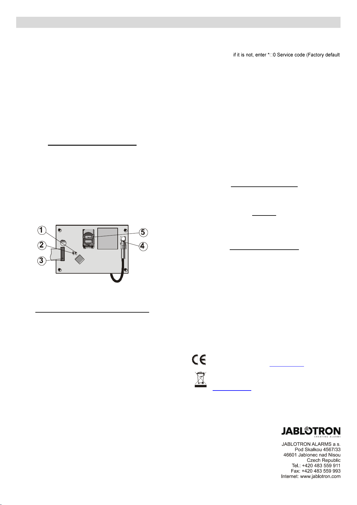
1.LED signalling connection to a GSM network; 2.LED signalling
image transmission; 3. control panel connector; 4. GSM antenna;
5.SIM card
Initial powering up of the communicator
If the communicator is installed in the control panel and its GSM
antenna is connected, then:
a) Have a suitable SIM card ready. It should be activated (see if it
works in a mobile phone first). If it requires a PIN code when
switching the phone on, then disable the PIN code request
upon the first use of the phone); e.g. Nokia: Menu / Settings /
Security settings / PIN code request / Off. The communicator can
work with a prepaid card, but we recommend using a tariff card
for more reliable functioning
b) Insert the SIM card into the communicator (to open the card
holder push its frame up a little)
c) Switch on the control panel power* (both mains and battery).
The communicator’s red LED should be lit = registering to the
GSM network; it should go off within a minute = registration
successful
d) If the red LED starts flashing after a while, switch off the control
panel power, put the SIM card into a mobile phone and check that
it registers to the network in the place where the control panel is
installed without any PIN code requests
e) Close the control panel cover, the alarm system should be in
Service mode -
setting: 8080) with the alarm system unset (disarmed)
f) Key in 98101 - to set the texts and voice messages of the
communicator to the English language
g) Key in 888 to measure the GSM signal strength (a number in the
range from 1/4 to 4/4 should be displayed). It should be at least
2/4 to ensure reliable functioning. If the signal is weak, change
the location of the control panel or try a SIM card from another
GSM provider (it is not recommended to use either a high-gain or
directional GSM antenna
h) If the GSM signal strength is sufficient, test the communicator
functions (system controlling via a mobile phone, etc), see the
installers / user manual on the supplied CD / DVD.
*) If the communicator is switched on without an inserted SIM card the
registration key for O-Link remote access is not generated. (Switch the
communicator off, insert the SIM and switch it on again).
Warning: If installed at a location near a national border where the
signal strength fluctuates, roaming to a foreign network is highly likely.
We therefore recommend blocking the roaming feature in the SIM card
to avoid unnecessarily high communication fees (contact your GSM
provider for details).
Communicator settings
Setting the communicator up is possible using Olink version 2.0 and
higher. Simple settings can also be done using the system keypad.
Manuals
Description of all functions and parameters can be found in the installer
and user manuals on the supplied CD / DVD. The CD / DVD also contains
a suitable version of Olink.
Technical specifications
Power 12V DC (from the control panel)
Stand-by consumption about 35 mA (depends on the GSM signal strength)
GSM band QUAD-BAND, 850/900/1800/1900MHz
Complies in configuration CIE OASIS system with
EN 50131-1, EN 50136-2-1 as follows ATS 4, ATS 5
if CID protocol is used and the repeating period is set to zero
(Sequence 06p0)
Operating environment –indoor general (-10°C to 40°C) Class II
Security Grade 2
Safety EN 60950-1
EMC ETSI EN 301489-1, ETSI EN 301489-7
EN 55022, EN 50130-4
Radio transmissions ETSI EN 301419-1 and EN 301511
CLIP protocol (caller ID + SMS) ETSI EN 300 089
Can be operated according to GSM Regulations
JABLOTRON ALARMS a.s. hereby declares that the JA-82Y is in
compliance with the essential requirements and other relevant
provisions of Directive 1999/5/EC. The original of the conformity
assessment can be found at www.jablotron.com - Technical Support
section
Note: Although this product does not contain any harmful materials
we suggest you return the product to the dealer or directly to the
producer after use. More detailed information can be found at
www.jablotron.com - Technical Support section


