jablotron JA-101KR User manual

User manual
MLJ57205 - EN user manual - desky.indd 1 20.9.2014 12:23:18

1
1. INTRODUCTION 3
2. OPERATING THE JABLOTRON 100 SYSTEM 3
2.1 Keypad code authorization 4
2.2 Using the system keypad 6
2.2.1 Using the segment keypads 6
2.2.1.1 Alarm Setting 9
2.2.1.2 Alarm Unsetting 9
2.2.1.3 Duress Access Control 10
2.2.1.4 Partial Alarm Setting 10
2.2.1.5 Terminating a triggered alarm 11
2.2.1.6 Section control from the keypad’s display menu 11
2.2.2 Using the JA-110E and JA-150E system keypads 12
2.2.2.1 Alarm Setting 14
2.2.2.2 Alarm Unsetting 15
2.2.2.3 Partial Alarm Setting 15
2.2.2.4 Duress Access Control 16
2.2.2.5 Terminating a triggered alarm 16
2.2.2.6 Section control by authorization 17
2.2.2.7 Section control from the keypad’s menu 17
2.3 Operating the system with a keyfob 17
2.4 Operating the system using a computer and a USB cable (J-Link) 18
2.5 Operating the system using the voice menu 18
2.6 Operating the system via the MyJABLOTRON web interface 18
2.7 Operating the system using the MyJABLOTRON smartphone app 20
2.8 Operating the system using SMS commands 20
2.9 Operating the system remotely using a computer (J-Link) 20
2.10 PG outputs control via… 21
3. BLOCKING / DISABLING THE SYSTEM 21
3.1 Blocking users 21
3.2 Blocking detectors 21
3.3 Disabling Timers 22
4. CUSTOMIZING THE SYSTEM 22
4.1 Changing a user access code 22
4.2 Changing, deleting or adding an RFID card/tag 22
4.3 Changing a username or phone number 22
4.4 Adding / deleting a user 23
4.5 Calendar events set up 23
TABLE OF CONTENTS

2
5. EVENT HISTORY 23
5.1 Using the LCD keypad 23
5.2 Using the J-Link software and a computer 23
5.3 Logging into MyJABLOTRON (web/smartphone) 23
6. WHAT IS THE MyJABLOTRON WEB INTERFACE? 24
7. PERIODICAL MAINTENANCE 24
8. TECHNICAL SPECIFICATIONS 25
9. GLOSSARY OF TERMS 26

3
1. INTRODUCTION
Thank you for choosing the JABLOTRON 100 security system. This system
is a unique flexible indoor solution for commercial and home security that offers
the use of both wired and wireless devices.
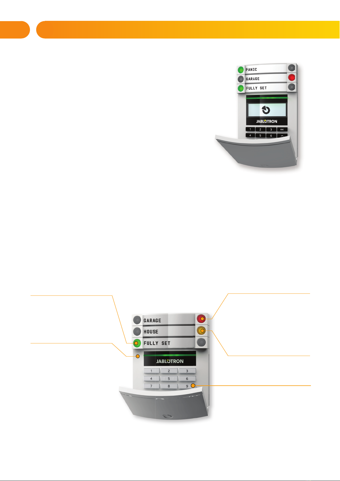
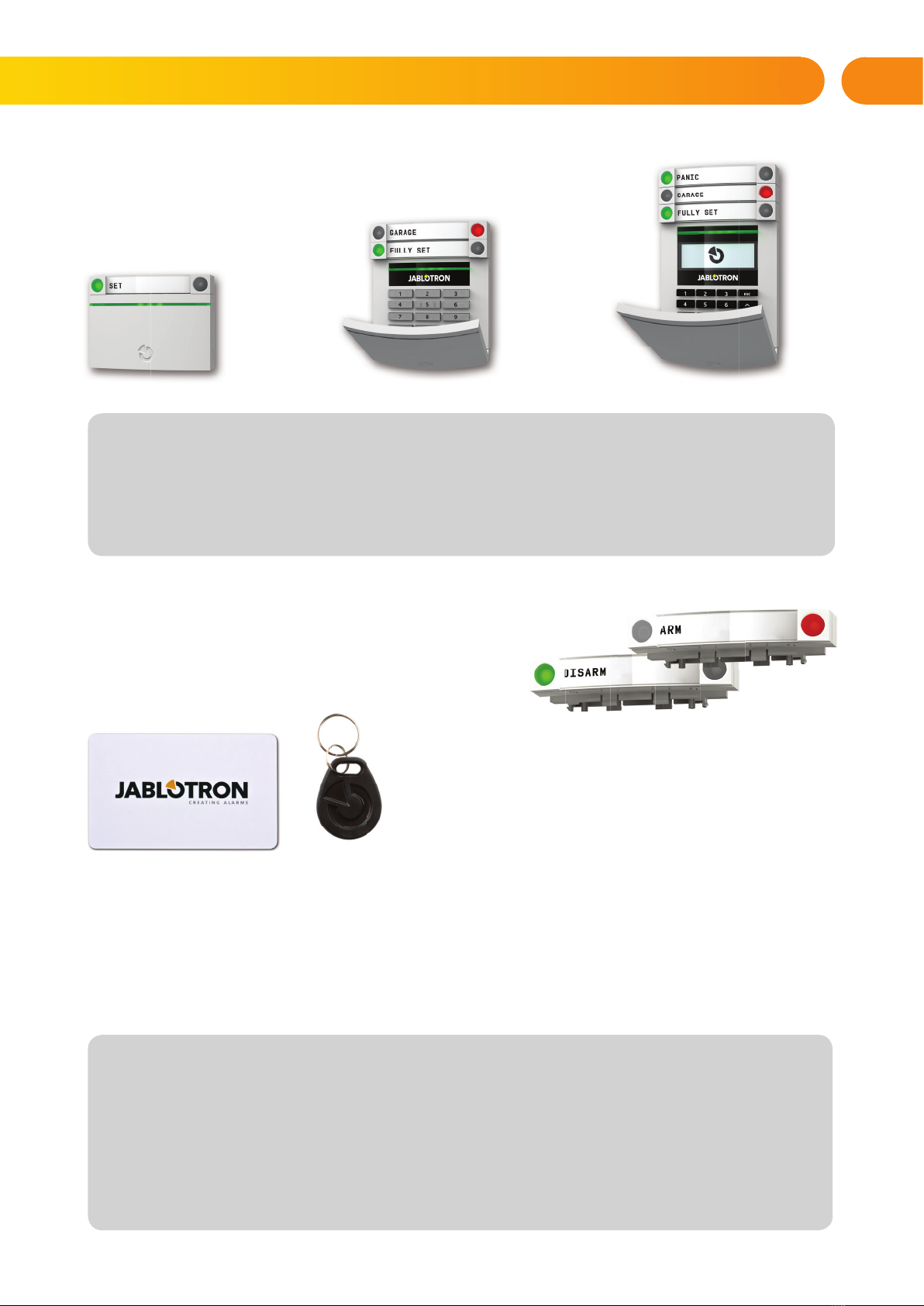
The JABLOTRON 100 is very easy to control. Simplicity of control consists
of two steps, authorization with a code or a RFID tag followed by pressing an
individual keypad segments with assigned function on a keypad. It is possible to use
a reversed method when the “Default” system profile is enabled. Press a segment
button first and then authorize. The control segments use a simple traffic light logic
which everyone can understand. The number of segments can be promptly adapted
to requirements of premises. The JABLOTRON 100 series offers a wide range of
detectors with timeless design. It can be operated from anywhere owing to complete
remote control access. The J-Link software (Windows XP and higher),
the MyJABLOTRON web interface and the MyJABLOTRON application for smart
phones allow you to control, program and monitor the system remotely.
The JABLOTRON 100 is designed for up to 300 users and it can be divided into
15 individual sections. Up to 120 detectors can be connected and the system offers
up to 32 multi-purpose programmable outputs (e.g. home automation).
The security system can be controlled in a number of different ways. To unset the alarm, authorization
in the form of user identification is always required. The system detects the identity of the users and allows them
to operate those parts of the system which they have been assigned to control. You can choose from different ways
of setting with or without authorization. When Standard authorization type is used, you don’t have to authorize
yourself because it is possible to set the system just by pressing the right segment button on a keypad.
The user name, date, and time are recorded and stored in the system‘s memory every time the system is accessed.
This information is available indefinitely. Any user can also cancel a triggered alarm (stop sirens from sounding) just
by authorization in any part of the system (depending on their access rights). However, that does not automatically
unset the system (unless the system’s default setting is changed).
Note: Depending on the configuration of the installation and system settings, some of the options described
below may not be available. Consult the configuration of the installation with your service technician.
Users and Their Access Rights
CODE
AUTHORIZATION
TYPE DESCRIPTION
ARC code This code has the highest level of authorization to configure the system’s behaviour and is exclusively
allowed to perform the system unblock after a triggered alarm. It can enter Service mode, access all tabs
with options including ARC communication to which it can deny access to a Service technician (Service
code). As long as the “Administrator-restricted Service/ARC right” parameter remains unchecked, the ARC
code can control all sections and PG outputs used in the system. This code enables to add more Administra-
tors and other users with a lower level of authorization assign them with codes, RFID tags and cards. It also
has a permission to erase alarm and tamper alarm memory. The number of ARC codes is limited only
by remaining capacity of the control panel.
Service code
(Service)
It can enter Service mode and configure the system’s behaviour. It has access to all tabs with
options including ARC communication unless the access is limited by the ARC technician. As long as
the “Administrator-restricted Service/ARC right” parameter remains unchecked, the Service code can control
all sections and PG outputs used in the system. It can create users with ARC permission, other Service
technicians, Administrators and other users with a lower level of authorization and assign them with access
codes, RFID tags and cards. The number of Service codes is limited only by remaining
capacity of the control panel. By the factory defaults, the code is 0*1010 and it cannot be erased.
Administrator
(Main)
This code has always full access to all sections and is authorized to control all PG outputs. The Administrator
can create other Administrator and other codes with a lower level of authorization and assign them with access
to sections and PG outputs, access codes, RFID chips and cards. Has permission to erase the alarm memory.
There can be only one main Administrator code which can’t be erased. When “Administrator-restricted Service
/ ARC right” is enabled, the administrator code must be authorized to confirm access for ARC and Service
technicians. By the factory defaults, the code is 1*1234.
2. OPERATING THE JABLOTRON 100 SYSTEM

4
2.1 KEYPAD CODE AUTHORIZATION
Authorization with a user code is done by typing a valid code into a keypad or with an RFID tag.
It is possible to use 4, 6 or 8-digit codes in the system.
The system can be configured to be used with or without prefix codes.
Code with a prefix: nnn*cccc
Meaning:
nnn is the prefix, which is number of the user’s position (0 to 300)
*is a separator (* key)
cccc is a 4, 6, or 8-digit code. Allowed codes… from 0000 to 99999999
Default control panel code Administrator: 1*1234; 1*123456; 1*12345678;
WARNING: The main Administrator code must start with the prefix 1,
The main Service code starts with the prefix 0
Prefix can be disabled for systems with a small number of users. Type of the code can be changed
only by an installation technician.
Code without a prefix: cccc
Meaning:
cccc cccc is a 4, 6 or 8-digit code. Allowed codes… from 0000 to 99999999
Default control panel code Administrator: 1234; 123456; 12345678;
2. OPERATING THE JABLOTRON 100 SYSTEM
CODE
AUTHORIZATION
TYPE DESCRIPTION
Administrator
(Other)
Has access to sections selected by the main Administrator to which the other Administrator can add new
users with the same or lower level of authorization to control sections and PG outputs, assign them with access
codes, RFID tags and cards. Has permission to erase the alarm memory in assigned sections.
When “Administrator-restricted Service/ARC right” is enabled, the administrator code must be authorized
as to confirm access for ARC and Service technicians. The number of Administrator codes (other) is limited
only by remaining capacity of the control panel. There is no code set by the factory defaults.
User This code has access to sections and PG control rights assigned by an Administrator. Users can add/
delete their RFID tags and access cards and change their own telephone numbers. It has permission to erase
the alarm memory in assigned sections. Users can change their codes provided that the system uses Codes with
prefixes. Selected users may have their access to sections limited by a schedule. The number of User codes
is limited only by remaining capacity of the control panel. There is no code set by the factory defaults.
Set This code is allowed only to set a designated section and is allowed to control (ON/OFF) PG outputs which
require authorization. Users with this level of authorization are not allowed to change their code and are not
allowed to erase the alarm memory. The number of Set codes is limited only by remaining capacity
of the control panel. There is no code set by the factory defaults.
PG only Allows the user to control programmable outputs with authorization only. This applies to both switching
on and off. Users with this level of authorization are not allowed to change their code and are not allowed
to erase the alarm memory. The number of PG only codes is limited only by remaining capacity of
the control panel. There is no code set by the factory defaults.
Panic This code is allowed only to trigger Panic alarm. A user of this code is not allowed to change it or erase
the alarm memory. The number of Panic codes is limited only by remaining capacity of the control panel.
There is no code set by the factory defaults.
Guard Code This is a code for a security agency. This level of authorization allows to set the whole system. However the guard
code can unset the system only during alarm or after it expired as long as the alarm memory is still active.
A user of this code is not allowed to change it or erase the alarm memory. The number of Guard codes is limited
only by remaining capacity of the control panel. There is no code set by the factory defaults.
Unblocking code This code is designated to unblock the system after System blocking by alarm. A user of this code
is not allowed to change it or erase the alarm memory. The number of Unblocking codes is limited only
by remaining capacity of the control panel. There is no code set by the factory defaults.

5
The security of access codes, contactless RFID devices and remote controls
A control panel enables each user to be assigned with one 4, 6 or 8-digit code and up to two RFID tags
for system authorization. User authorization is required during each operation via keypad, voice menu,
a computer, web or mobile apps. Code length affects number of possible combinations and therefore
code security.
The number of code combinations depends on the configuration:
Ways to improve protection against guessing the valid code:
aUsing a code with more digits (6 or 8-digit codes)
aMore advanced types of authorization, such as “Card confirmation with a code“
or “Double authorization”.
Control panel
parameters
4 DIGITS 6 DIGITS 8 DIGITS
Using
„Code with a prefix“
= 104= (10.000) = 106= (1.000.000) = 108= (100.000.000)
„Code with a prefix“
and „Duress access
control“ both disabled
= 104– (Number of users – 1) = 106– (Number of users – 1) = 108– (Number of users – 1)
„Code with a prefix“
disabled; „Duress access
control“ enabled
≤ 104– ((Number of users – 1) * 3) ≤ 106– ((Number of users – 1) * 3) ≤ 108– ((Number of users – 1) * 3)
Using only an RFID
card with a range of 14
characters (6 constant + 8
variable)
= 108= (100.000.000) = 108= (100.000.000) = 108= (100.000.000)
„Code with a prefix“ and
„Card confirmation with
a code“ both enabled
= ( 108* 104) = 1012 =
(1.000.000.000.000)
= ( 108* 106) = 1014 =
(100.000.000.000.000)
= ( 108* 108) = 1016 =
(1.000.000.000.000.000)
„Code with a prefix“
disabled; „Card con-
firmation with a code“
enabled
= 108
* (104– (Number of users – 1))
= 108
* (106– (Number of users – 1))
= 108
* (108– (Number of users – 1))
2. OPERATING THE JABLOTRON 100 SYSTEM

6 2. OPERATING THE JABLOTRON 100 SYSTEM
Continuous yellow
PARTIALLY SET
Access module
CARD READER / KEYPAD
Continuous red
SET / ON
Flashes red
ALARM /
ALARM MEMORY
Ways of operating the JABLOTRON 100
On-site:
aSystem keypad
aSystem keyfob
aComputer using a USB cable and the J-Link software
Remotely:
aTelephone using the voice menu
aComputer, via the MyJABLOTRON web interface
a MyJABLOTRON smartphone application
aMobile – via SMS
aComputer, via the internet using the J-Link software
aDialling-in from an authorized telephone number
(only for operating programmable outputs)
Flashes red
ALARM / ALARM MEMORY
Continuous green
EVERYTHING OK
Flashes green
CONTROL
Continuous yellow
FAULT
Flashes yellow
UNSUCCESSFUL
SETTING
Continuous green
UNSET / OFF
Flashes green
ENTRY DELAY
2.2 USING THE SYSTEM KEYPAD
2.2.1 USING THE SEGMENT KEYPADS
JABLOTRON 100 system may be controlled by a variety of access modules which let you not just control
but also display statuses of individual segments. The system can be operated directly (setting or unsetting
the system and other automation functions) using two-button segments on the keypad. The segment buttons are
clearly labelled and coloured (using traffic light logic) so that each segment’s status is distinctly indicated.
A segment can also be used to indicate a status (e.g. opened garage door) or to control various automated
devices (for example heating or window shutters). The maximum number of segments is 20 for one access
module. A segment can also be set up to call for help in an emergency (medical or panic alarm).

7
The various types of access modules
and their combinations:
When unsetting the alarm using the segment buttons,
user authorization is always required. When setting the alarm
and controlling automated processes using the segment
buttons, user authorization is optional for each segment.
A user can be authorized by entering their assigned code or
using their RFID card/tag. Each user can have
one code and up to two RFID chips (cards or tags).
Recommended contactless chips: JABLOTRON 100, Oasis and Azor or other third-party chips compatible
with 125 kHZ EM Unique standard. If higher security is required the alarm system can be set up to use confirmed
authorization using RFID chips and codes (optional).
If the users want to control multiple segments simultaneously, he must authorize himself and then press
segments of the particular sections subsequently. This way the user can unset for example the house
and the garage within one single authorization.
2. OPERATING THE JABLOTRON 100 SYSTEM
RFID Card reader
allows control of the system using
segments and user authorization using
contactless method (RFID card/tag).
Keypad with a card reader
the user can control the system using
segments and authorization, either by
entering a code or the contactless me-
thod (RFID card/tag), or a combination
of both for higher security.
Keypad with display and card reader
the user can control the system
using segments and authorization,
using either a code, the contactless
method (RFID card/tag), both code
and card/tag for higher security, or by
authorizing and using the options avai-
lable on the keypad’s LCD display.
The keypad authorization code can consist of up to eleven digits: a prefix (one to three digits),
an asterisk * (which separates the prefix and main code), and a 4,6 or 8-digit code depending
on configuration (for example : 123*12345678, or 1*12345678). All users can change their own codes
which follow the prefix. The code can be changed from the LCD keypad, the J-Link software
(Windows XP and higher) or MyJABLOTRON app.
The prefix can be omitted for premises with a smaller number of users. In this case only
a code is required (4,6 or 8-digit code depending on configuration). These codes can be changed
only by the system administrator or a service technician.

8
Structure and description of the internal LCD keypad menu
2. OPERATING THE JABLOTRON 100 SYSTEM
Cancel warning
indication
Section Control
Event memory
Setting
prevented
Faults in
system
Bypassed
detectors
System status
Settings
Display setting
Allows you to cancel alarm/unsuccessful setting
indication in all sections to which the user has
access rights
Allows you to control the system‘s sections to
which the user has access rights and are enabled
in the internal settings.
Displays a detailed list of the event memory.
Shows a list of triggered detectors preventing
setting the system, provided this option is
activated in the control panel configuration.
Displays a list of all detectors indicating
system faults from sections
to which the user has access rights.
Displays a list of all blocked detectors
in sections to which a user has access rights.
Shows system status
(list of triggered detectors, triggered tamper
contacts, low batteries, bypassing, etc.).
Allows editing of users and devices
(only when USB is disconnected).
Allows adjustment of keypad backlight intensity
and display contrast.
Administrator or User
authorization
by the code
or RFID tag/card

9
2.2.1.1 ALARM SETTING
While setting the alarm, if any detector is triggered (e.g. an open window) the system will react (based on the
system configuration) in one of the following ways:
aDetectors will guard automatically after they switch to standby mode (default setting)
aThe system will optically indicate triggered detectors with a segment flashing red for 8 seconds and the
system will set automatically once this period has expired.
aSetting the section with triggered detectors is also possible by pressing the segment button on the right
side repeatedly. This way a user confirms an intention to set the section with a triggered detector (e.g. an
opened window). Otherwise the system will not set.
aA triggered detector will prevent the section from being Set. This status is optically indicated by a fla
shing red segment button. The detector preventing setting will be shown on the keypad’s display menu.
Unsuccessful setting is indicated by yellow a flashing indication button.
Consult the installation with a service technician in order to program the desired behaviour of the system.
2.2.1.2 ALARM UNSETTING
Note: If the “Unset section by authorization only during entrance delay” parameter is enabled, then mere
authorization will unset such section where the entrance delayed has been triggered.
Consult the installation with a service technician in order to program the desired behaviour of the system.
1. Authorize using the keypad.
Sections which can be controlled
are lit up and the backlit indication
button will start flashing green.
2. Press the right button
(the one which isn’t lit up) to set
a particular section. It is possible
to set more sections subsequently.
The delay between sections
selection must not be longer than
2 seconds.
3. The command is executed and
the keypad acoustically indicates
the exit delay. The section is set
now, only the detectors with a
“Delayed Zone” reaction provide
time to leave the guarded area
during the Exit delay. The segment
button of the set section turns red.
1. When you enter the building
(triggering a detector with a
“Delayed zone” reaction), the
system starts indicating entrance
delay with a continuous tone and
flashing a green segment button
of the section in which the delayed
entrance has been triggered.
Authorize yourself using the
keypad – the green indication light
of the authorization panel starts
flashing.
2. Press the left segment button
of the sections you want to unset.
3. The command is executed
and the segment buttons turn
green to indicate an unset section.
2. OPERATING THE JABLOTRON 100 SYSTEM

10
2.2.1.3 DURESS ACCESS CONTROL
Provides unsetting of the system in a special mode. The system seemingly unsets, however it triggers
a silent panic alarm, which is reported to selected users (including ARC).
Unsetting under duress is executed by adding 1 to the last number in a valid code. Contact your service
technician if you want to use this feature.
Example for a code with the prefix:
Valid code: 2*9999 Code for unsetting under duress: 2*9990
Example for a code without the prefix:
Valid code: 9999 Code for unsetting under duress: 9990
2.2.1.4 PARTIAL ALARM SETTING
The system can also be configured to be partially set which allows guarding only by certain detectors
in a section. Example: At night, it is possible to set the door and window detectors only, while motion detectors
inside a house do not react to anything.
To set the entire premises in which partial setting is enabled, the button to set the system has to be pressed twice.
After the button is pressed once it flashes yellow, after it is pressed a second time it flashes red.
If the system is partially set already – showing a continuous yellow light – the entire system can be fully set
by authorization and pressing the yellow button. Once the button is pressed, the system will be fully set and
the button turns red.
Partial setting can be configured in a way that authorization is not required.
1. Authorize yourself using
the keypad (enter a code or hold
a card or a tag up to the reader).
The green backlit indication button
will start flashing.
2. Press the right segment button
of the selected section.
3. The command is executed
and the segment button turns
permanently yellow to indicate
a partially set section.
2. OPERATING THE JABLOTRON 100 SYSTEM

11
2.2.1.5 TERMINATING A TRIGGERED ALARM
A triggered alarm in progress is indicated by a rapidly flashing red segment button and a backlit
indication button. You need to authorize yourself using the keypad in order to terminate the alarm.
The section remains set, a rapidly flashing red segment button indicates the alarm memory. Indication will keep
on flashing even after the system has been unset.
If the alarm memory indication was activated during your absence, search for the cause of the alarm
in the event history and be very careful when entering and checking the premises or wait until the security agency
arrives (provided your system is connected to an Alarm Receiving Centre).
The segment alarm memory indication remains on until the system is set once again. Alternatively, it can
be cancelled by unsetting the system one more time. Alarm indication can be also cancelled from a keypad with
an LCD display in the Main menu – Cancel warning indication.
Indication of a triggered tamper alarm can be terminated only by a Service technician.
Note: When using the “Default” system profile, it is possible to first select a particular action by pressing
a segment button and then confirm it by authorization using the keypad.
Terminating an alarm using a remote control will also unset the corresponding section.
2.2.1.6 SECTION CONTROL FROM THE KEYPAD’S DISPLAY MENU
Statuses of sections are displayed in the left top part of the display.
A fully set section is shown by a number in a rectangle filled with black colour.
A partially set section is depicted by a framed number.
Control from the keypad menu:
aAuthorization by a valid code or an RFID chip
aEnter the menu by pressing ENTER
aSection Control →ENTER
aSelect the desired section using arrows
aPressing ENTER repeatedly will change between section statuses
(partially set / set / unset)
aPress ESC to exit the menu
1. Authorize yourself
using the keypad (enter
a code, hold a tag up
to the reader).
2. Press the left segment
button of the section
in which the alarm has
been triggered.
3. Unsetting is finished
and sirens are silenced.
The green flashing
button indicates un-
setting of the particu-
lar section. The red
flashing light indicates
alarm memory.
4. Authorize yourself
and press the green
button again to cancel
the alarm memory
indication.
5. The segment indicates
the unset section with
a continuously lit up
green button.
2. OPERATING THE JABLOTRON 100 SYSTEM

12
2.2.2 USING THE JA-110E AND JA-150E SYSTEM KEYPADS
Statuses of individual sections are indicated by status indicators A, B, C, D above the LCD display and by the
functions buttons. The control panel can be operated directly (setting or unsetting the alarm and other automation
functions) using function buttons on the keypad. The function buttons and the status indicators
A, B, C, D are colourfully backlit in order to clearly indicate the section status.
aGREEN – Unset
aYELLOW – Partially Unset
aRED – Set
Authorization can be done by entering an access code on the keypad or using an RFID card/tag assigned to a
particular user. Each user can have one code and one RFID chip (a card or a tag).
If the users want to control multiple sections simultaneously, they must authorize themselves and then
press function buttons of the particular sections subsequently. This way the users can unset all sections
(for example the house and the garage) within one single authorization.
di id l i i di d b i di A B C D b h LCD
Status indicators
A, B, C, D
LCD display
Function buttons
A, B, C, D
System indicator
The keypad and the
RFID reader
2. OPERATING THE JABLOTRON 100 SYSTEM

13
Cancel warning
indication
Section Control
Event memory
Setting
prevented
System status
Settings
Display setting
Allows you to cancel alarm/unsuccessful setting
indication in all sections to which the user has
access rights
Allows you to control the system‘s sections
to which the user has access rights and are
enabled in the internal settings.
Displays a detailed list of the event memory.
Shows a list of triggered detectors preventing
setting the system, provided this option
is activated in the control panel configuration.
Bypassed
detectors
Displays a list of all blocked detectors in sections
to which a user has access rights.
Faults
in system
Displays a list of all detectors indicating
system faults from sections to which
the user has access rights.
Shows system status (list of triggered detectors,
triggered tamper contacts, low batteries,
bypassing, etc.).
Allows editing of users and devices
(only when USB is disconnected).
Allows adjustment of keypad backlight intensity
and display contrast.
Administrator or
User authorization
by the code or RFID
tag/card
2. OPERATING THE JABLOTRON 100 SYSTEM
Structure and description of the internal LCD keypad menu

14
2.2.2.1 ALARM SETTING
While setting the alarm, if any detector is triggered (e.g. an open window) the system will react (based on the
system configuration) in one of the following ways:
o The control panel will set itself. Triggered detectors will be blocked automatically.*)
o The system will optically indicate triggered detectors with a function button flashing red for 8 seconds
and the control panel will set automatically once this period has expired (triggered detectors will be
blocked). *)
o Setting the section with triggered detectors is also possible by pressing the function button repea-
tedly. The user must confirm an intention to set the section with a triggered detector (e.g. an opened
window). Otherwise the system will not set.
o A triggered detector will prevent the section from being set. This status is optically indicated by a
function button flashing red. The detector preventing setting will be shown on the LCD display menu.
*) WARNING: Options a) and b) are not supported by EN 50131, gr.2
(selected control panel system profile).
If a detector with the “Instant zone alarm” reaction is triggered during an exit
delay or if a detector with the “Delayed zone alarm” reaction stays triggered after the
exit delay has expired, then the control panel will unset again. Unsuccessful setting
is indicated by a system indicator flashing yellow, reported to the ARC and indicated
by an external siren (applies to the security Grade 2).
If the control panel is configured to be set without authorization then it is not
necessary to authorize yourself. All you have to do is press a function button of a
particular section. It is also possible to configure the control panel to be set simply
by authorization.
WARNING: Setting without authorization automatically lowers the maximum security level to Grade 1.
Consider all possible risks related to using this function.
Consult the installation with a project consultant or a service technician in order to program the desired be-
haviour of the alarm system.
1. Authorize yourself using
the keypad. Function buttons
A, B, C, D will light up and the
system indicator starts flashing
green.
2. Press the function button to set
a particular section. It is
possible to set more sections
subsequently. The delay between
sections selection must not be
longer than 2 seconds.
3. The command is executed
and the keypad acoustically
indicates the exit delay. The
section is set now, only the
detectors with a “Delayed Zone”
reaction provide time to leave
the guarded area during the Exit
delay. The status indicator and
a function button of the set
section will turn red.
2. OPERATING THE JABLOTRON 100 SYSTEM

15
2.2.2.2 ALARM UNSETTING
Note: If the “Unset section by authorization only during entrance delay” parameter is enabled, then mere autho-
rization will unset a section where the entrance delayed has been triggered. This option should be used with
caution when using multiple sections.
Consult the installation with a service technician in order to program the desired behaviour of the system.
2.2.2.3 PARTIAL ALARM SETTING
WARNING: This is an additional function of the alarm system.
The system can also be configured to be partially set which allows guarding only by certain detectors
in a section.
Example: At night, it is possible to set the door and window detectors only, while selected motion detectors will
not trigger the alarm when somebody moves inside the section.
1. When you enter the building
(triggering a detector with a
“Delayed zone” reaction), the
system starts indicating an entrance
delay with a continuous tone, the
system indicator and a function
button, both flashing red, of the
section in which the delayed
entrance has been triggered.
2. Authorize yourself using the
keypad – the system indicator will
start flashing green.
3. Press the function buttons of
the sections you want to unset.
4. The command is executed.
The function buttons and the
system indicator turn green
to indicate unset sections.
1. Authorize yourself using
the keypad (enter a code or
hold an RFID card or tag up to
the reader). The system indicator
button will start flashing green.
2. Press the function button of
the selected section.
3. The command is executed
and the function button turns
permanently yellow to indicate
a partially set section.
2. OPERATING THE JABLOTRON 100 SYSTEM

16
To set the entire premises in which partial setting is enabled, hold down the button to set the control panel for
2 seconds or press it twice. After the button is pressed once it shows continuous yellow light, after it is pressed
a second time it shows continuous red light.
If the system is partially set already – the function button shows a continuous yellow light – the entire system
can be fully set by authorization and pressing the yellow button for a longer time. Once the button is pressed,
the system will be fully set and the button turns red.
Partial setting can be configured in a way that authorization is not required.
In order to unset the control panel when it is partially set, press the yellow button. The control panel will unset
and the button turns green.
2.2.2.4 DURESS ACCESS CONTROL
Provides unsetting of the control panel in a special mode. The system seemingly unsets, however it triggers
a silent panic alarm, which is reported to selected users (including ARC).
Unsetting under duress is executed by adding 1 to the last number in a valid code. Contact your service
technician if you want to use this feature.
Example:
Valid code: 9999 Code for unsetting under duress: 9990
2.2.2.5 TERMINATING A TRIGGERED ALARM
A triggered alarm in progress is indicated by the status indicator and the function button rapidly flashing
red. You need to authorize yourself using the keypad in order to terminate the alarm. The section remains set, a
rapidly flashing red function button indicates the alarm memory. Indication will continue flashing even after the
system has been unset.
WARNING: If the alarm memory indication was activated during your absence, always enter the building with
caution, search for the cause of the alarm in the event history and be very careful when checking the premises or
wait until the security agency arrives (provided your system is connected to an Alarm Receiving Centre).
The alarm memory indication remains on until the system is set once again. Alternatively, it can be also can-
celled from the keypad menu: Main menu – Cancel warning indication.
Indication of a triggered tamper alarm can be terminated only by a Service technician and Administrator.
Note: When using the “Default” system profile, it is possible to select a particular action by pressing a function
button first and then confirm it by authorization using the keypad.
Terminating an alarm using a remote control will also unset the corresponding section.
1. Authorize yourself using the
keypad (enter a code or hold a
tag up to the reader).
2. Press the function button
of the section in which the alarm
has been triggered.
3. Unsetting is finished and sirens
are silenced. Rapidly
alternately flashing function
buttons (green/red) and the status
indicators indicate the alarm
memory.
2. OPERATING THE JABLOTRON 100 SYSTEM

17
2.2.2.6 SECTION CONTROL BY AUTHORIZATION
The service technician can configure the control panel to be controlled just by authorization. This way the status
of all sections can change by authorization on a keypad (by typing an access code or using an RFID chip).
2.2.2.7 SECTION CONTROL FROM THE KEYPAD’S MENU
Control from the keypad menu:
o Authorize yourself using a valid code or an RFID chip
o Enter the menu by pressing ENTER
o Section Control →ENTER
o Select the desired section using arrows
o Pressing ENTER repeatedly will change between section statuses
(partially set / set / unset)
Partial setting:
Fully set:
o Press ESC to exit the menu.
1
1
2.3 OPERATING THE SYSTEM WITH A KEYFOB
Keyfobs must be enrolled into the system by the installer. The keyfob can be linked
to specific users, which will prevent SMS text message notification to the user who
is interacting with the system at the moment (if notification parameters are set
up in this way). The keyfob can provide either bi-directional communication,
confirming the execution of a command with a coloured indicator light,
or one-way without any confirmation. Keyfobs control and indicate battery
status and are equipped with optical and acoustic indication.
Bi-directional keyfob
The button functions are differentiated by lock icons. The closed lock icon sets
programmed sections; the opened lock icon unsets them. Correct command execution
is confirmed by an LED light; unsetting – green, setting – red. A communication fault (out
of the control panel’s range) is indicated by a yellow LED light flashing once. The buttons with symbols of full and
empty circles can control another section. Buttons of the keyfob can also be configured to control PG outputs in
different modes: the first button switches on/ the second switches off, each button can have an individual function
when impulse or change functions are used. For more functions, it is possible to press two buttons at the same time.
This way a 4-button keyfob can have up to 6 individual functions or one PG status output (e.g. turn the lights on and
off), alternatively two PG outputs (e.g. a garage door and door lock).
If the system is configured to Set after confirmation (chapter 2.2.1.1) the detector will indicate unsuccessful
setting with a green LED light if a device is triggered. It is necessary to confirm setting by pressing
the lock button again. A set section will be confirmed by a red LED light.
The keyfob buttons can be blocked to prevent accidental pressing. A command will be sent out when
a button is pressed repeatedly.
A low battery is indicated acoustically (with 3 beeps) and optically with a yellow flashing LED after
pressing a button.
For more information, consult configuration of the remote control with your service technician.
2. OPERATING THE JABLOTRON 100 SYSTEM

18
One-way keyfobs
One-way keyfobs send a signal every time a button is pressed without receiving feedback from the control
panel. Sending a signal is confirmed only by a short flash of the red LED and alternatively with a beep.
The button functions are differentiated by lock icons. The closed lock icon sets programmed sections; the
opened lock icon unsets them. The buttons with symbols of full and empty circles can control another section
or one status PG output (e.g. to turn the lights on and off) or two PG outputs (e.g. a garage door and door lock).
A low battery is indicated by a red LED and acoustically (3 fast beeps).
2.4 OPERATING THE SYSTEM USING
A COMPUTER AND A USB CABLE (J-LINK)
The JABLOTRON 100 can be operated locally or remotely (see chapter 2.9) using
a computer and installed J-Link software (Windows XP and higher), which can be used
for user management (add/remove users, change their level of authorization, phone
numbers, codes, card/tags, etc.).
The J-link software is available for local connection with a control panel.
It is located on the system’s security drive (FLEXI_CFG/j-link), which will appear after
the control panel is connected to a PC via USB.
It is possible to set / unset the system using icons on the lower bar of the
program or with the “Status” buttons in the “Section” tab. If a keypad with at least one
controllable segment is used with the system, then it is possible to set/unset
the system in the J-Link software using an on-screen virtual keypad (click on “Keypad“
in the main menu).
WARNING: When the system is controlled via PC, it doesn’t check for triggered devices while setting.
This may lead to setting with a triggered device. Be careful when you control the system this way!
2.5 OPERATING THE SYSTEM USING
THE VOICE MENU
The system can be controlled from a mobile phone or land line through a simple voice
menu, which guides the user through a series of options in the preconfigured language.
To access the voice menu, you just dial the alarm system’s phone number.
Access to the voice menu can be enabled either to all telephone numbers
without restrictions or alternatively only to authorized phone numbers stored
in the control panel. Depending on the configuration, authorization by entering
a valid code on a phone keypad may be required. When the user enters the menu,
the system will give an update of the current status of all sections assigned to the user.
The caller then can control these sections, either individually or collectively,
using phone keypad and available menu options.
The system default is set up to answer incoming calls after three rings (approximately
15 seconds).
2.6 OPERATING THE SYSTEM VIA
THE MyJABLOTRON WEB INTERFACE
The JABLOTRON 100 system can be easily and conveniently operated using your computer via the internet
and the MyJABLOTRON web interface, which is accessible from www.myjablotron.com. For more information
about this web interface please see the chapter 6.
MyJABLOTRON - PROFI version
Depending on your country or region, a web account in MyJABLOTRON can be set up by an authorized
JABLOTRON partner. The login name is the user‘s e-mail address. The password for the first log in will
be sent to this address. The password can be changed anytime in the user settings.
2. OPERATING THE JABLOTRON 100 SYSTEM

19
Once logged into the account, the system will display all active devices which can be monitored or controlled.
The “Overview“ menu includes “Section”, and “Automation (PG)” tabs.
Depending on the type of detectors used, the menu may also include tabs like
“Thermostats and thermometers”, “Meters” “History” and “Gallery”.
Tabs:
aSections – enables you to view and operate all sections in the system.
aKeypads – enables you to view all virtual keypads the way they are installed
in the premises. It is possible to control them by clicking on a segment just like
pressing a segment button on the real keypad. You will be asked you to enter
an authorization code upon the first request to control the system. While you are
logged in, subsequent actions will not require repeated authorization.
aAutomation (PG) – enables you to view all programmable system outputs.
aThermostats and thermometers – allows you to view the current temperatures
and history graphs from a list of used thermostats and thermometers. Depending on the configuration,
it is possible to regulate temperature in the building.
aMeters – an overview of all installed meters (electricity, gas and water).
aGallery – enables you to take snapshots with any installed camera verification devices, or look at past photos
and video sequences taken by these devices.
The bottom of the home page has an overview of the most recent system events.
MyJABLOTRON offers free notifications (via SMS, e-mail, or push notifications) for selected system
section events, programmable outputs, thermometers or meters. These notifications can be set up
in the “Settings“ menu.
Each system can have only one main user with Administrator rights (owner). This user has the right
to share a whole building or its selected parts (single sections, PG outputs, photo verification and
measuring devices) with other users whose MyJABLOTRON accounts will be created automatically after
the system sharing is configured. If a user already has a MyJABLOTRON account, the shared installation will
appear in the user’s dashboard as another active device. Notification of shared access will be sent, along with
the password, to the e-mail address (login name) of the new user.
MyJABLOTRON - LITE version
Depending on your country (or region) customers may be able to create an account and/or services
in the LITE version of MyJABLOTRON web app.
The LITE service is limited in functionality and minimizes demands for data transfer. LITE is based
on the PROFI version with some modifications:
The LITE version in comparison with PROFI version:
aDoesn’t maintain a constant connection with a control panel
aEstablishing connection takes approx. 1 minute
aThe current status appears after successful connection
aControlling the system (sections or PG outputs) is possible after successful connection
aThe event history is not available
aThe system doesn’t send event notifications (SMS, email, push messages)
aVirtual system keypads are not available
aA detector’s photo gallery and photos upon request are not available
aThermometers, electricity meters and other supported automation devices are not displayed
A password will be sent to the user’s e-mail address, which also serves as a login name.
The password can be changed at any time in the settings.
Once logged into the account, the system shows all active devices that can be monitored or controlled,
depending on the registered version of MyJABLOTRON (PROFI or LITE).
2. OPERATING THE JABLOTRON 100 SYSTEM
This manual suits for next models
1
Table of contents
Other jablotron Control Panel manuals

jablotron
jablotron HESTIA-915 User manual

jablotron
jablotron OASiS JA-83K User manual

jablotron
jablotron JA-80K Oasis User manual

jablotron
jablotron JA-82KRC-US User manual

jablotron
jablotron Profi JA-63K User manual

jablotron
jablotron OASiS JA-82KRC User manual

jablotron
jablotron JA-63 PROFI" User manual

jablotron
jablotron JA-63 PROFI" User manual

jablotron
jablotron Oasis JA-80 User manual

jablotron
jablotron JA-82K OASiS User manual