manuals.online logo
Brands
  1. Home
  2. •
  3. Brands
  4. •
  5. jablotron
  6. •
  7. Control Unit
  8. •
  9. jablotron JA-112M User manual

jablotron JA-112M User manual

JABLOTRON ALARMS a.s.
Pod Skalkou 4567/33 46601 Jablonec n. Nisou
Czech Republic www.jablotron.com
||
|
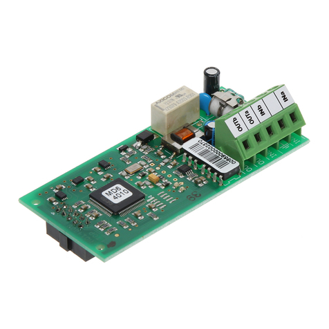
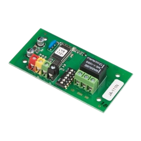
The JA-112M BUS module for magnetic contact – 2 inputs
The JA-112M BUS module for magnetic contact – 2 inputs - 1 - MLM57101
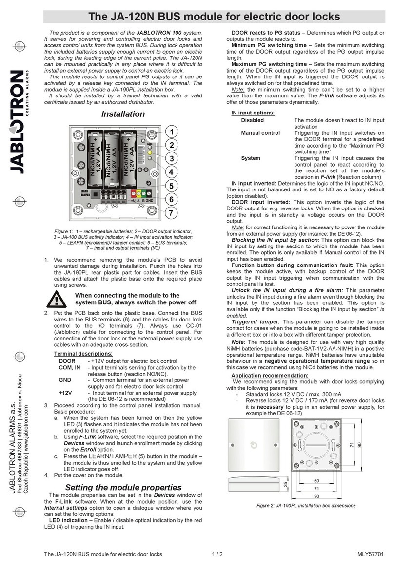
The JA-112M is a BUS device of the JABLOTRON 100+system.
It has two wire inputs that can be connected unbalanced, single
or double balanced or in a roller mode. It is primarily used to connect
magnetic contact (e.g. SA-201, SA-203, SA-211). The module has
a status reaction (reports its activation and deactivation) and takes two
positions in the system. It should be installed by a trained technician
with a valid certificate issued by an authorized distributor.
Installation
When selecting the right location for the module, bear in mind that
the wires leading to the detectors should not be longer than 100 m.
Figure 1: 1 – cover tab; 2 – LED indicator
1. Open the module cover by pressing the cover tab (1).
2. Take out the PCB from the plastic base by pressing the tab
on the left part (3).
3. Push the cables through the plastic base and attach
it to the selected place with screws. For a more comfortable
installation there are cut-out holes (4) in the plastic and also a cable
lead with fixing clips under the module board (5).
When connecting the module to the BUS,
always switch the system power off.
4. Insert the PCB back and connect the cables to the terminals (9, 10).
Figure 2: 3 – PCB tab; 4 – cut-out holes; 5 – fixing clips for cables coming from the top
cut-out holes; 6 – red and yellow LED indicator; 7 – production code; 8 – tamper sensor;
9 – magnetic contact terminal; 10 – BUS terminal;
5. If you want to use a balanced loop for better protection
of a magnetic contact connection use a 1 kΩresistor in series with
the detector (see the following figure). The balance function must
be enabled in the module settings.
Figure 3: Loop balancing
6. Proceed by following the control panel installation manual. Basic
instructions:
a. When the module is switched on, the yellow LED lights up.
With flashing it indicates that the module has not been enrolled
into the system.
b. Open the F-Link software, select an unused position
in the Devices tab and click on the Enroll button to enter
the Enrollment mode.
c. Click on the option Scan/add new BUS devices, select
the JA-112M module and double-click to confirm selection.
The yellow LED goes off.
7. Close the module cover and test the module’s function.
Notes:
−The module can also be enrolled into the system by entering its
production code in the F-Link software. You can find the production
code on the sticker (7) placed on the module board. All numbers
under the bar code must be entered (1400-00-0000-0001).
−The module can also be enrolled into the system by pressing
the tamper sensor (8).
−The number of modules is limited only by the current consumption
from the control panel and by the number of positions in the control
panel.
−It can take up to 1 minute to load the initial input states after
the system boot.
−Warning!The module occupies two consecutive positions (each
input has its own position). Should the second position be occupied,
it will be automatically overwritten.
−If only the first input is used, the second input can be deleted
by selecting it in the F-Link software and pressing “Delete”
to release the position for another device.
−By deleting the first input, the module will always be deleted
completely.
−To meet the EN 50131-3 standard it is necessary to secure
the cover tab (1) with a supplied screw.
Setting the module properties
Open the F-Link software, go to the Devices Tab. Click
on the Internal settings button at any of the module’s positions to open
a dialogue window with internal settings for the input (according
to the clicked position) where you can set the following options,
(* indicates default settings):
To set the module to comply with
Grade 2 classification, use the System
profiles function in the Parameters tab
in the F-Link software.
Inputs 1 and 2: tabs with complete input settings. Each input can
be set differently.
Input function: Enabled*
Disabled – no reaction (the input is disabled).
Enabled – reacts to a change of connected detector (standby NC),
see the figure in F-Link software.
Single balanced – there has to be an RACT resistor put in series with
an ACT activation contact (see the figure in the F-Link software). To set
its value use the Balancing resistor parameter that is visible when you
select this function. The input is activated when the resistance
of the loop changes by 30 %.
Double balanced – there has to be an RTMP resistor put in series with
a TMP tamper contact and the activation contact has to be bridged
by an RACT resistor (see the figure in the F-Link software). To set its
value, use the Balancing resistor parameter. The values of the RTMP and
RACT balancing resistors can be different, see the Balancing resistor
parameter.
The loop can have up to 3 states: Standby – the value of measured
loop resistance equals RTMP; Activation – the value of measured loop
resistance equals RTMP + RACT (if multiplicity is used – RTMP + n * RACT);
Tamper – the value of measured loop resistance is different than
previous values. To ensure reliable detection the device assumes
a variability of values (±30%).
Roller – reacts to short repeated disconnection pulses with
an adjustable sensitivity to two levels: Impulse1 – activation after
3 pulses within 2 minutes; Impulse2 – activation after 5 pulses within
2 minutes. When the input is opened for more than 3 s a tamper alarm
is triggered. After activation the module is in idle status for 10 s.
LED indication: Enabled*The red LED indicates a change of state
of any input with a short flash.
Impulse behaviour: Disabled* can be used for all functions except
the roller. The default option is disabled, the input works in a status
mode. It means the input reacts to disconnection/connection (activation
The JA-112M BUS module for magnetic contact – 2 inputs
The JA-112M BUS module for magnetic contact – 2 inputs - 1 - MLM57101
and deactivation) of the loop. If enabled the input will only react
to activation and after 2 s it will go to standby automatically.
Inverted input reaction: (valid for an Enabled or Balanced input only)
the default setting for the input reaction is NC (normally closed).
Enabling this option sets the reaction to NO (normally open).
Balancing resistor: can be used for a Single balanced input and for
a Double balanced input. The default value is 1k0*.
For a Single balanced input select the RACT value of balancing resistor
from the pre-set values.
For a Double balanced input select the RTMP and RACT value of resistor
for the detection of tampering and activation from the pre-set values
(the selected value applies to both resistors)
Delayed input reaction: time filter to increase the immunity to false
activation 0.5 s* (setting 0.1 s … 300 s). It determines for how long
the input has to be triggered for the control panel to record (react to)
the activation. For a Double balanced input the setting can be 0.5 s …
300 s).
Copy of input settings: this button allows you to copy the settings
of the other input to a currently programmed input.
Test input measuring:this tab shows the currently measured
resistance at a specific input (loop). The graphical representation fully
respects the input settings (function, balancing and its value).
It visualizes the current status of the measured value. Due
to the recording of measured values over time it shows a visible curve
with all changes and you can test all detectors this way.
Technical specification
Power From control panel BUS 12 V (9 … 15 V)
Current consumption in standby mode 7 mA
Current consumption for cable choice (maximum) 12 mA
Maximum length of cable to the magnetic contact 100 m
Dimensions 110 x 44 x 26 mm
Weight 51 g
Classification Grade 2/II. indoor general (According to EN 50131-1)
Operational environment Indoor general
Operational temperature range -10 °C to +40 °C
Average operational humidity 75 % RH, non-condensing
Certification body Trezor Test s.r.o. (no. 3025)
Also complies with EN 50131-1 ed. 2+A1+A2, EN 50131-3,
EN 50130-4 ed. 2+A1, EN 55032, EN 50581
JABLOTRON ALARMS a.s. hereby declares that the JA-112M
is in compliance with the relevant European Union
harmonisation legislation: Directives No: 2014/35/EU,
2014/30/EU, 2011/65/EU, when used as intended. The original
of the conformity assessment can be found
at www.jablotron.com – the Downloads section.
Note:
Although this product does not contain any harmful
materials we suggest you return the product to the dealer
or directly to the producer after use.

Other jablotron Control Unit manuals

jablotron JA-113E User manual

jablotron

jablotron JA-113E User manual

jablotron JA-154E User manual

jablotron

jablotron JA-154E User manual

jablotron JA-120N User manual

jablotron

jablotron JA-120N User manual

jablotron JA-120N User manual

jablotron

jablotron JA-120N User manual

jablotron UC-82 User manual

jablotron

jablotron UC-82 User manual

jablotron JA-190X User manual

jablotron

jablotron JA-190X User manual

jablotron JA-154E User manual

jablotron

jablotron JA-154E User manual

jablotron JB-111N User manual

jablotron

jablotron JB-111N User manual

jablotron JA-120N Instruction manual

jablotron

jablotron JA-120N Instruction manual

jablotron JA-101K User manual

jablotron

jablotron JA-101K User manual

jablotron JA-120N User manual

jablotron

jablotron JA-120N User manual

jablotron JA-120N User manual

jablotron

jablotron JA-120N User manual

jablotron AC-82 User manual

jablotron

jablotron AC-82 User manual

jablotron JA-153E User manual

jablotron

jablotron JA-153E User manual

jablotron JA-153E User manual

jablotron

jablotron JA-153E User manual

jablotron AC-82 User manual

jablotron

jablotron AC-82 User manual

jablotron JA-113E User manual

jablotron

jablotron JA-113E User manual

jablotron JA-152E User manual

jablotron

jablotron JA-152E User manual

jablotron JA-114E User manual

jablotron

jablotron JA-114E User manual

jablotron JA-101K User manual

jablotron

jablotron JA-101K User manual

Popular Control Unit manuals by other brands

Aqua Medic T controller twin Operation manual

Aqua Medic

Aqua Medic T controller twin Operation manual

Plast-O-Matic True Blue RVDT Series Assembly/Installation/Operating Instructions

Plast-O-Matic

Plast-O-Matic True Blue RVDT Series Assembly/Installation/Operating Instructions

Contro l4 C4-AM15-120-Z-B installation guide

Contro l4

Contro l4 C4-AM15-120-Z-B installation guide

red lion DA 4G LTE CAT4 installation guide

red lion

red lion DA 4G LTE CAT4 installation guide

Icom UR-FR5100 instructions

Icom

Icom UR-FR5100 instructions

BIG TREE TECH U2C user manual

BIG TREE TECH

BIG TREE TECH U2C user manual

Sel 651R installation instructions

Sel

Sel 651R installation instructions

red lion ITMA product manual

red lion

red lion ITMA product manual

Krom Schroder VAS Series operating instructions

Krom Schroder

Krom Schroder VAS Series operating instructions

FEB 856 Maintenance manual

FEB

FEB 856 Maintenance manual

Keyautomation CT-724 Series Instructions and warnings for installation and use

Keyautomation

Keyautomation CT-724 Series Instructions and warnings for installation and use

FOR-A HVS-AUX16B Operation manual

FOR-A

FOR-A HVS-AUX16B Operation manual

SPX FLOW APV DELTA DKR2 instruction manual

SPX FLOW

SPX FLOW APV DELTA DKR2 instruction manual

Edgetech P.A.C.S. USER HARDWARE MANUAL

Edgetech

Edgetech P.A.C.S. USER HARDWARE MANUAL

Redline RDL-3000-RMD product manual

Redline

Redline RDL-3000-RMD product manual

BOSSCO Ecomaxx Supplemental manual

BOSSCO

BOSSCO Ecomaxx Supplemental manual

FrontRow JUNO ITR-01 Installer's guide

FrontRow

FrontRow JUNO ITR-01 Installer's guide

SPX FLOW Power Team A operating instructions

SPX FLOW

SPX FLOW Power Team A operating instructions

manuals.online logo
manuals.online logoBrands
  • About & Mission
  • Contact us
  • Privacy Policy
  • Terms and Conditions

Copyright 2025 Manuals.Online. All Rights Reserved.