manuals.online logo
Brands
  1. Home
  2. •
  3. Brands
  4. •
  5. jablotron
  6. •
  7. Control Unit
  8. •
  9. jablotron JB-111N User manual

jablotron JB-111N User manual

JABLOTRON ALARMS a.s.
Pod Skalkou 4567/33 46601 Jablonec n. Nisou
Czech Republic www.jablotron.com
||
|
The JB-111N BUS signal PG output module
The JB-111N BUS signal PG output module 1 / 2 MLY22101
The JB-111N is a component of the JABLOTRON 100+ system.
It provides an output relay switch. It can be used for
switching on/off the lights, ventilators, etc. The relay can
be controlled with a programmable control panel (PG) output
or according to the status of a section (set = relay on) or when
there is an alarm in a chosen section (alarm = relay on). The device
should be installed by a trained technician with a valid certificate
issued by an authorized distributor.
Installation
The module can be installed into the JA-19xPL mounting box
(by Jablotron) or into the control panel box. In order to comply with
the security grade 2 classification, the module must be installed into
the JA-194PL or JA-195PL mounting box together with the JA-111H
TRB module.
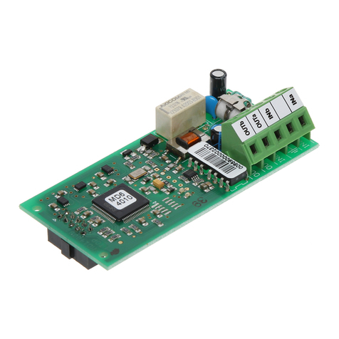
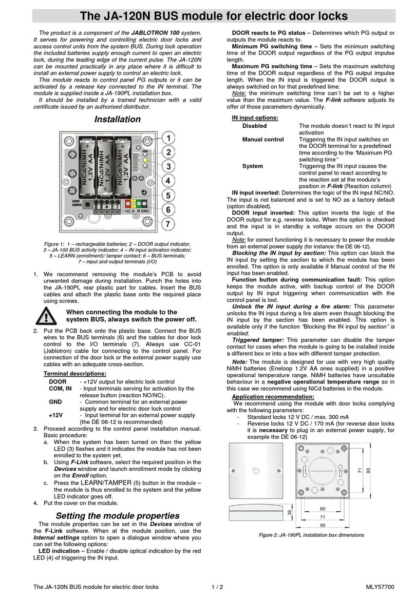
Figure: 1 – BUS terminals; 2 – red relay switching indicator;
3 – configuration switch; 4 – output relay; 5 – relay terminals
1. Use the switch (3) to set the required number of the PG output
or the number of the section to which the relay should react
(see tables).
2. Connect BUS wires to the terminals (1).
When connecting the module to the system
BUS, always switch the power off.
If the module is installed outside the protected
area, the JA-110T BUS insulator should be used
for the external section of the wiring.
The output contact does not contain
an overload protection.
3. Switch on the system and test its functioning
4. Check the supply voltage at the BUS terminals (red, black)
when the relay is activated. The voltage must be at least 9V.
5. Connect the controlled device to the relay output terminals (5).
Notes:
 The module does not occupy any position in the control panel
(it is not enrolled into the system).
 If you enroll multiple modules with identical settings
to the system, they will have the same reaction.
 The number of modules is only limited by the power
consumption from the BUS.
 The setting of individual programmable outputs is done
in the PG outputs window in the F-Link software. A detailed
description of the setting is available in the control panel
installation manual.
 If the output reacts to a setting of a section, it is triggered when
the selected section is fully set.
 If the output reacts to an alarm, it is triggered when there
is external or internal warning (EW or IW).
Table 1: The output reacts to the PG output state.
NONONON
1 234567 8 1234 5678 1 234567 8 1234 5678
ON ON ON ON
1 234567 8 1234 5678 1 234567 8 1234 5678
ON ON ON ON
1 234567 8 1234 5678 1 234567 8 1234 5678
ON ON ON ON
1 234567 8 1234 5678 1 234567 8 1234 5678
ON ON ON ON
1 234567 8 1234 5678 1 234567 8 1234 5678
ON ON ON ON
1 234567 8 1234 5678 1 234567 8 1234 5678
ON ON ON ON
1 234567 8 1234 5678 1 234567 8 1234 5678
ON ON ON ON
1 234567 8 1234 5678 1 234567 8 1234 5678
PG
2
PG
10
PG
1
14
PG
15
PG
16
PG
8
PG
7
PG
PG
6
9
PG
5
PG
13
PG
4
PG
12
PG
3
17
PG
18
PG
19
PG
20
PG
PG
PG
11
PG
29
PG
30
PG
31
24
PG
25
PG
26
PG
27
PG
28
21
PG
22
PG
23
PG
PG
PG
32
NONONON
1 234567 8 1234 5678 1 234567 8 1234 5678
ON ON ON ON
1 234567 8 1234 5678 1 234567 8 1234 5678
ON ON ON ON
1 234567 8 1234 5678 1 234567 8 1234 5678
ON ON ON ON
1 234567 8 1234 5678 1 234567 8 1234 5678
ON ON ON ON
1 234567 8 1234 5678 1 234567 8 1234 5678
ON ON ON ON
1 234567 8 1234 5678 1 234567 8 1234 5678
ON ON ON ON
1 234567 8 1234 5678 1 234567 8 1234 5678
ON ON ON ON
1 234567 8 1234 5678 1 234567 8 1234 5678
41 4 9 57
PG PG PG PG
PG PG PG PG
33
3 5 43 5 1 59
PG PG PG PG
3 4 42 5 0 58
PG PG PG PG
3 7 45 5 3 61
PG PG PG PG
3 6 44 5 2 60
PG PG PG PG
3 9 47 5 5 63
PG PG PG PG
3 8 46 5 4 62
PG PG PG PG
4 0 48 5 6 64
NONONON
1 234567 8 1234 5678 1 234567 8 1234 5678
ON ON ON ON
1 234567 8 1234 5678 1 234567 8 1234 5678
ON ON ON ON
1 234567 8 1234 5678 1 234567 8 1234 5678
ON ON ON ON
1 234567 8 1234 5678 1 234567 8 1234 5678
ON ON ON ON
1 234567 8 1234 5678 1 234567 8 1234 5678
ON ON ON ON
1 234567 8 1234 5678 1 234567 8 1234 5678
ON ON ON ON
1 234567 8 1234 5678 1 234567 8 1234 5678
ON ON ON ON
1 234567 8 1234 5678 1 234567 8 1234 5678
PG PG PG PG
6 5 73 8 1 89
PG PG PG PG
6 7 75 8 3 91
PG PG PG PG
6 6 74 8 2 90
PG PG PG PG
6 9 77 8 5 93
PG PG PG PG
6 8 76 8 4 92
PG PG PG PG
7 1 79 8 7 95
PG PG PG PG
7 0 78 8 6 94
PG PG PG PG
7 2 80 8 8 96
NONONON
1 234567 8 1234 5678 1 234567 8 1234 5678
ON ON ON ON
1 234567 8 1234 5678 1 234567 8 1234 5678
ON ON ON ON
1 234567 8 1234 5678 1 234567 8 1234 5678
ON ON ON ON
1 234567 8 1234 5678 1 234567 8 1234 5678
ON ON ON ON
1 234567 8 1234 5678 1 234567 8 1234 5678
ON ON ON ON
1 234567 8 1234 5678 1 234567 8 1234 5678
ON ON ON ON
1 234567 8 1234 5678 1 234567 8 1234 5678
ON ON ON ON
1 234567 8 1234 5678 1 234567 8 1234 5678
PG P G PG
9 8 10 6 1 1 4 12 2
PG PG PG PG
PG
9 7 10 5 1 1 3 12 1
PG PG PG PG
100 108 116 124
PG PG PG PG
9 9 10 7 1 1 5 12 3
PG PG PG PG
102 110 118 126
PG PG PG PG
101 109 117 125
PG PG PG PG
104 112 120 128
103 111 119 127
PG PG PG PG
The JB-111N BUS signal PG output module
The JB-111N BUS signal PG output module 2 / 2 MLY22101
Table 2: The output reacts
to setting the chosen section
Table 3: The relay reacts
to an alarm in the chosen section
Technical specifications
Power from control panel BUS 12 V DC (9 …15 V)
Current consumption (relay off/on) 5 mA/25 mA
Current consumption for cable selection 25 mA
Relay contact rating:
Maximum switched voltage 50 V AC/24 V DC
Maximum switched current 2 A
Minimum switched current 10 mA
Dimensions 78 x 40 x 15 mm
Weight 23 g
Classification Security grade 2/Environmental class II
(according to EN 50131-1)
Only when installed into the JA-194PL or JA-195PL mounting box
together with the JA-111H TRB module!
Operational environment indoor general
Operational temperature range -10 °C to +40 °C
Average operational humidity 75 % RH, non-condensing
Certification body Trezor Test s.r.o. (no. 3025)
Complies with EN 50131-1 ed. 2+A1+A2, EN 50131-3,
EN 50130-4 ed. 2+A1, EN 55032, EN 50581
JABLOTRON ALARMS a.s. hereby declares that the JB-111N
is in a compliance with the relevant Union harmonisation
legislation: Directives No: 2014/30/EU, 2011/65/EU, when used
as intended. The original of the conformity assessment can
be found at www.jablotron.com – Section Downloads.
Note: Although this product does not contain any harmful
materials we suggest you return the product to the dealer
or directly to the producer after use. For more detailed
information visit www.jablotron.com.
NONONON
1 234567 8 1234 5678 1 234567 8 1234 5678
ON ON ON ON
1 234567 8 1234 5678 1 234567 8 1234 5678
ON ON ON ON
1 234567 8 1234 5678 1 234567 8 1234 5678
ON ON ON ON
1 234567 8 1234 5678 1 234567 8 1234 5678
ON ON ON ON
1 234567 8 1234 5678 1 234567 8 1234 5678
ON ON ON ON
1 234567 8 1234 5678 1 234567 8 1234 5678
ON ON ON ON
1 234567 8 1234 5678 1 234567 8 1234 5678
ON ON
1 234567 8 1 234567 8
SC SC
SC SC
513
SC SC
8
210
S C SC AL AL
311311
AL AL
412412
S C SC AL AL
AL AL
19 19
S C SC AL AL
210
513
S C SC AL AL
614614
8
SECTION:
SET
SECTION:
A
L
A
R
M
AL AL
715715
SC AL

Other jablotron Control Unit manuals

jablotron AC-82 User manual

jablotron

jablotron AC-82 User manual

jablotron JA-120N Instruction manual

jablotron

jablotron JA-120N Instruction manual

jablotron JA-113E User manual

jablotron

jablotron JA-113E User manual

jablotron JA-190X User manual

jablotron

jablotron JA-190X User manual

jablotron UC-82 User manual

jablotron

jablotron UC-82 User manual

jablotron JA-120N User manual

jablotron

jablotron JA-120N User manual

jablotron JA-153E User manual

jablotron

jablotron JA-153E User manual

jablotron JA-153E User manual

jablotron

jablotron JA-153E User manual

jablotron JA-152E User manual

jablotron

jablotron JA-152E User manual

jablotron AC-82 User manual

jablotron

jablotron AC-82 User manual

jablotron JA-120N User manual

jablotron

jablotron JA-120N User manual

jablotron JA-120N User manual

jablotron

jablotron JA-120N User manual

jablotron JA-112M User manual

jablotron

jablotron JA-112M User manual

jablotron JA-113E User manual

jablotron

jablotron JA-113E User manual

jablotron JA-101K User manual

jablotron

jablotron JA-101K User manual

jablotron JA-120N User manual

jablotron

jablotron JA-120N User manual

jablotron JA-114E User manual

jablotron

jablotron JA-114E User manual

jablotron JA-101K User manual

jablotron

jablotron JA-101K User manual

jablotron JA-154E User manual

jablotron

jablotron JA-154E User manual

jablotron JA-154E User manual

jablotron

jablotron JA-154E User manual

Popular Control Unit manuals by other brands

Honeywell T7560A installation instructions

Honeywell

Honeywell T7560A installation instructions

GEM 8253 operating instructions

GEM

GEM 8253 operating instructions

Kemper PROTECT RPZ operating instructions

Kemper

Kemper PROTECT RPZ operating instructions

CAME Z Series manual

CAME

CAME Z Series manual

Beninca CP.J3-SW manual

Beninca

Beninca CP.J3-SW manual

MFB DRUM-07 operating manual

MFB

MFB DRUM-07 operating manual

Seitron RYK01M manual

Seitron

Seitron RYK01M manual

Velleman VMA402 user manual

Velleman

Velleman VMA402 user manual

Tomoe 304YA instruction manual

Tomoe

Tomoe 304YA instruction manual

Tyco CCU/IO-485 Install instructions

Tyco

Tyco CCU/IO-485 Install instructions

Victaulic 317 Series Installation and maintenance instructions

Victaulic

Victaulic 317 Series Installation and maintenance instructions

Drews HCC 11 Description and operating manual

Drews

Drews HCC 11 Description and operating manual

Harvia XAFIR CS170 Instructions for installation and use

Harvia

Harvia XAFIR CS170 Instructions for installation and use

ARTERY AT32F421 Series Reference manual

ARTERY

ARTERY AT32F421 Series Reference manual

GMI D1045Y instruction manual

GMI

GMI D1045Y instruction manual

Watts Tekmar 305V installation manual

Watts

Watts Tekmar 305V installation manual

Pepperl+Fuchs VAA-2E-KE1-S Original instructions

Pepperl+Fuchs

Pepperl+Fuchs VAA-2E-KE1-S Original instructions

Kobelt 2544 Owner's Operation, Installation & Maintenance Manual

Kobelt

Kobelt 2544 Owner's Operation, Installation & Maintenance Manual

manuals.online logo
manuals.online logoBrands
  • About & Mission
  • Contact us
  • Privacy Policy
  • Terms and Conditions

Copyright 2025 Manuals.Online. All Rights Reserved.