JABSCO 37010 Series User manual

1
Model 37010-Series
ELECTRIC MARINE TOILET
Push Button Operation
FEATURES
• WhiteVitreousChinaBowlAvailableinTwoSizes
• BakedEnamelSeat&CoverinCompactor
HouseholdSize
• FlexibleImpellerFlushPump
• PermanentMagnetTypeMotor,FullyEnclosed,with
StainlessSteelShaft
• HighCapacityMaceratorandBowlScavengerPump
• Built-inBackFlowPreventer
• AllCorrosionResistantMaterialforMarineUse
VARIATIONS
VOLTAGE COMPACT SIZE HOUSEHOLD SIZE
12VdcEMC 37010-0090 37010-1090
24VdcEMC 37010-0096 37010-1096
INSTALLATION
TheJabscoelectrictoiletmaybeinstalledaboveorbelow
thewaterline.Flushpumpisself-primingwithaverticallift
up to 4 feet; discharge macerator pump can operate
againstaverticalheadupto4feet.
Inletandoutletseacocksshouldbeeasilyaccessibleand
be positive shut off valves. If seacocks cannot be
convenientlyoperatedfromtoiletlocation,installsuitable
shutoffvalvesforinletanddischargeconnections.
Base assembly may be moved 90° to accommodate
connectionsandprovideaccessibilityforservicing.
Surfacewheretoiletismountedshouldbeflattoprevent
distortionoftoiletbase.
PLUMBINGCONNECTIONS-Connectinlethoseusing
either5/8"or3/4"IDhose(asleeveisincludedtoadapt
pumpinletfrom5/8"to3/4").Makesureallinletconnections
areairtightandfreeofsharpbendsorrestrictions.
Connect 1" or 1-1/2" hose to discharge port (Adaptor
98023-0080 is included to convert discharge port to
1-1/2"IDhose),andmakesuitableconnectiontoholding
tank or other discharge system. Avoid sharp bends or
restrictions.
Forabovewaterlineinstallations,acheckvalvemayhave
tobeinstalledintheflushwaterintakelinetoensurerapid
pumppriming.Toretainwaterinbowl,makealoopinthe
dischargelineabout8inchesabovebaseofbowl.
DANGER
!
CAUTION
!
WARNING
!
WARNING Floodhazard.Anytoiletinstalledbelowthewaterline
orwhichmaybebelowthewaterlineatanyangleof
heelortrimmustbeintalledwithproperlypositioned
ventedloops.Failuretodosocanresultinflooding
whichcancauselossofpropertyandlife.
Do not connect the toilet to the vessels
potablewaterforitssourceofsupply.Todosocanresult
incontaminationofpotablewatersupply.Iffreshwateris
preferredforflushing,provideaseparatefreshwatertank
tosupplywatertothetoiletonly.
DONOTCONNECTINLETHOSETOAPRESSURIZED
WATERSYSTEM.
Ifthetoiletis,orcanbe,belowwaterlineatanynormal
(includingstatic)attitudeofvesselheeland/ortrim,a3/4"
VentedLoopFittingmustbeinstalledinthelengthofhose
connecting the flushing pump to the inlet seacock. The
VentedLoopFittingmustbepositionedsoitremainsslightly*
abovethewaterlineatallanglesofheelandtrim.
Insomeinstallationswhenaventedloopisinstalledinthe
intake hose, the flushing pump primeability and flow
characteristics are reduced and may adversely affect
toilet function.Torestore pump performance,connect a
solenoid valve (Jabsco No. 37068-2000) to the vent air
inlet to interrupt the air supply during the flush cycle.
Screwthe¼”brassconnectorontotheventedloopand
wire the solenoid in parallel with the toilet motor. See
Diagram1forinstallationandwiringillustration.
*Recommendedminimumheightabovewaterlineis6".
ELECTRICAL CONNECTIONS - Select a location for
theswitchandinstructionplate,makingsurewireleads
fromboththetoiletandpowersourcecanberoutedto
theswitch.Ensurethepanelwhereinstallingswitchis
no more than 1" thick. Drill a 5/8" mounting hole and
installswitchandinstructionplate.Usestrandedcopper
wireofthecorrectsize(determinedfromtheelectrical
specificationschart)toconnectonesideoftheswitchto
thepositivepowersource.Anappropriatesizefuseor
CAUTION

2
equivalent circuit breaker (determined from electrical
specifications chart) must be installed in the positive
power lead within seven inches of the power source.
Connect the other side of the switch to the orange
(positive) motor lead. Connect the black (negative)
motor lead to the negative side of the battery or
groundedbussbar.
NOTICE: Correct motor polarity (orange to positive,
black to negative) is important. Reverse polarity can
damage motor and void warranty. Full voltage at the
motorisrequiredtoproperlyoperatetheElectricToilet.
Thetoiletmustbewiredinacircuitindependentofall
otheraccessories.
ELECTRICAL SPECIFICATIONS
AMP FUSE WIRE SIZE PER FEET OF RUN*
VOLTAGE DRAW SIZE 0'-10' 10'-15' 15'-25' 25'-40' 40'-60'
12Vdc 16 25 #12 #10 #10 #8 #6
24Vdc 8 15 #16 #14 #12 #10 #10
*Lengthofrunistotaldistancefrompowersourcetoproductandbacktoground.
OPERATING INSTRUCTIONS
Make sure inlet and outlet seacocks are all open; push
button
tooperate.Operateuntilbowliscompletelyflushed
anddischargepumphasscavengedwaterfrombottomof
bowl.
The Jabsco electric marine toilet will provide years of
troublefreeserviceifproperlyused. Itwillhandle waste
andtoilettissue.ItwillNOThandlerags,sanitarynapkins
orhardsolidobjects.
Ifbowldoesnotpumpoutandbeginstofill,partiallyclose
inletvalveuntil bowlisclearedandcompletelypumped
out.Thenoperateforafewsecondswithbothvalvesopen
toclearentiretoiletanddischargesystem.Formaximum
safety,whentoiletisnotinuseorvesselisunattended,
closeboththeinletanddischargeseacocks.
Todrainforwinterlay-up,closeinletvalveandoperatefor
afewsecondsuntilallwaterispumpedout.
After long periods of non-use, toilet and pump may dry
out.Toeaseinitialstart-up,putaboutonequartofwater
inbowlandletstandawhilebeforeinitialuse.
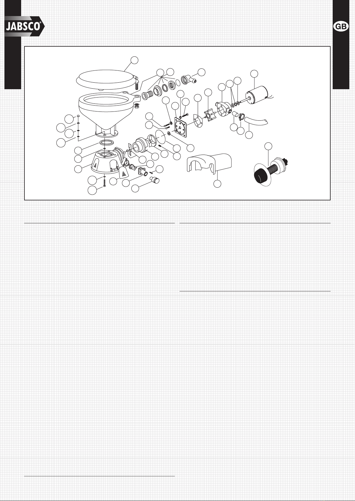
DISASSEMBLY
DANGER
!
CAUTION
!
WARNING
!
WARNING Floodhazard.Closeinletandoutletseacockspriorto
disassembling toilet. Failure to do so can result in
floodingwhichcancauselossofpropertyandlife.
Disconnectpumpinginletanddischargehoses.Remove
fourscrews,KeyNo.25,pullout complete motor,pump
andmaceratorassembly.Ifassemblydoesnotslideout
easily,pushforwardandpullbacksharplyseveraltimes
tofreemaceratorhousingfrombase.
Remove discharge port, Key No. 12, and joker valve.
Unscrewchopperplate,Key No.14,byturningcounter-
clockwise, facing plate. Prevent shaft from turning by
placing screwdriver in discharge port and locking
centrifugal impeller blade. Remove macerator housing.
Loosen impeller set screw and slide impeller off motor
shaft.
Removefourflatheadscrewsandtwowashers,KeyNos.
20,21,&22.Removetheplasticwearplate,KeyNo.23,
withsealingsleeve,KeyNo.19,andgasket,KeyNo.26.
Slidepumpassemblyoffmotorshaft.Replaceallwornor
damagedparts,cleanremainingparts.
ASSEMBLY
Presssealintobodywithlipfacingimpeller;becareful
nottococksealinbore.Installpumpbodyonmotorand
positiononregister.Lubricateimpellerborewithpump
greaseandinstallimpeller.Positionthegasketagainst
the body and install the wearplate ensuring the two
plasticsealingwashersareundertheheadsofthetop
andbottomscrews.NOTE:Thecurrentplasticwearplate
supercedestheearlierbrasswearplateandwithitthe
stainless steel wearplate is no longer used. Slide the
rubber sealing sleeve on the motor shaft and push it
into its recess in the wearplate. Relocate centrifugal
impeller on shaft, about 1/8" from the wearplate, and
tightenset screw.Place maceratorhousing overshaft
andcentrifugalimpeller,putlockwasheronendofshaft
and screw chopper plate on shaft and tighten. Install
O-ring in O-ring groove in wearplate surface, a little
grease will help hold in place, make sure inside body
surfaces are clean, line up slot in base with key on
maceratorhousing,slidepumpassemblyintobaseand
tighten with the four screws.Turn motor on for one or
twosecondstobesurecentrifugalimpellerisfree.
NOTE:Theswitchonthesideof
the solenoid is inactive and will
notaffectoperation.
-
+
-
DISCHARGE
TO
NEGATIVE
TO
POSITIVE
TO
NEGATIVE VENTED LOOP
Heeled
Waterline
Static
VIEW A
SWITCH
INLET
VIEW A
VENT TO
ATMOSPHERE
1/4" BSP
BRASS
CONNECTOR
(Screws on to
Vented Loop) Use PTFE tape
to seal
connector
onto Vented
Loop
ELECTRICAL
CONNECTIONS
Diagram1

3
PARTS LIST
Key Description Qty. Part Number
1 Seat,LidandHingeSet 1
CompactToilet 29097-1000
RegularToilet 29127-1000
1A HingeSet(1Pair) 1
CompactToilet 29098-1000
RegularToilet 29098-2000
2 Bowl,CompactSize 1 29096-0000
Bowl,RegularSize 1 29126-0000
3&4 BowlSpud&Intake 1 29048-0000
Elbow&O-ring
5 Clamp 1 18753-0044
6 Hose 1 29035-1001
7 BowlInstallationHardware 1 18753-0637
7A PhillipsHeadScrew** 4
7B Washer,Starlock** 4
7C HexNut**(twoplaces) 4
7D Washer,Plastic** 4
7E WasherStainlesssteel** 8
7F NutCap** 4
8 O-RingBowl/Seal 1 44101-1000
9 BaseAssembly** 1 37004-1000
10 1-1/2"Adaptor,DischargePort 1 98023-0080
11 JokerValve*** 1 44106-1000
12 1"DischargePort** 1 44107-1000
13 Screw** 3 96050-0568
14 ChopperPlate†withLockNut 1 37056-1000
15 MaceratorHousing† 1 37014-0000
16 CentrifugalImpeller† 1 37006-0000
17 SetScrew† 1 18753-0492
18 O-ring*† 1 43990-0066
19 SealingSleeve† 1 37036-1000
20 Screw† 2 91009-0096
21 Screw† 2 91010-0130
22 Washer,Fiber*† 2 35445-0000
23 WearplateKit‡† 1 37018-0000
24 LockWasher#10,StainlessKit† 4
25 Screw† 4 91027-0011
26 Gasket*† 1 12558-0000
27 FlexibleImpeller*† 1 6303-0003
28 Body† 1 12554-0000
29 Seal&Retainer*† 1 1040-0000
Key Description Qty. Part Number
30 Slinger† 1 6342-0000
31 Motors:
Motor-12VoltEMC† 1 37064-0000
Motor-24VoltEMC† 1 37065-0000
32 Adaptor 2 93003-0240
33 Switch&Plate 1 37020-0000
34 MotorCover† 1 43990-0051
35 ScrewCover(3each) 1 37003-1000
ServiceKit 37040-0000
Motor/PumpAssy.12VEMC† 37041-0010
Motor/PumpAssy.24VEMC† 37041-0011
* PartsSuppliedwithServiceKit37040-0000.
** Partsincludedwithbase37004-1000.
‡ Wearplate#23includesSealingSleeve#19andPump/
BaseO-ring#18.
† PartsincludedinMotor-PumpAssembly.
O
T
H
S
U
P
F
L
U
S
H
T
R
I
C
C
E
L
E
T
O
I
L
E
T
8
9
10
11
14
12
13
21
20
4
15 16 17
18
22
23
24
25
26
27
28 29 30
31
32 5
6
3
2
7F
7C
7E
7D
7A
34
33
19
1
7B 35
7C
EXPLODED VIEW
TO
BOWL
ELBOW

4
DIMENSIONAL DRAWING
INCHES(MILLIMETRES)
A B C D E F G
COMPACTSIZEBOWL 19-3/4(493) 4-13/16(123) 13-13/16(351) 13-7/8(352) 17-3/4(451) 9-7/8(251) 7-5/8(194)
HOUSEHOLDSIZEBOWL 21-3/4(543) 5-11/16(148) 14-5/8(372) 14-3/4(375) 19-3/4(502) 11-1/4(286) 8-1/2(216)
D Overall Width
1 (25)
Dia
4
(102)
6 (152)
B
5/16
(8) 3-1/8
(79)
5/8 (16) Dia
2 Places
C
FG
E
2 Leads - 11 (279) Long
12-15/16
10-7/8
A
3-1/2
(89)
7-3/8
(187)
2-1/2
(64)
3-7/8
(98)
4
(102) 5+3/8
(137)
5/8
(16)
MOTORCOVER
Form: 43000-0612 Rev. 01/2009
USA
ITTCorporation
CapeAnnIndustrialPark
Gloucester,MA01930
Tel:(978)281-0440
Fax:(978)283-2619
UK
ITTIndustries
BingleyRoad,Hoddesdon
HertfordshireEN110BU
Tel:+44(0)1992450145
Fax:+44(0)1992467132
JAPAN
NHKJabscoCompanyLtd.
3-21-10,Shin-Yokohama
Kohoku-Ku,Yokohama,222-0033
Tel:+81-045-475-8906
Fax:+81-045-477-1162
ITALY
JabscoMarineItalia
ViaTommaseo,6
20059Vimercate,Milano
Tel:+390396852323
Fax:+39039666307
GERMANY
JabscoGmbH
Oststrasse28
22844Norderstedt
Tel:+49-40-535373-0
Fax:+49-40-535373-11
Warranty:Allproductsofthecompanyaresold,andallservicesofthecompanyareofferedsubjecttothecompany’swarrantyandtermsofsale,copiesofwhichwillbefurnisheduponrequest.
Detailscorrectattimeofprinting.Wereservetherighttochangespecicationswithoutpriornotice.
©Copyright2009ITTIndustries,RegisteredEnglandNo.81415,registeredofce:JaysCloseViablesEstate,Basingstoke,Hants,RG224BA
www.jabsco.com
This manual suits for next models
4
Other JABSCO Toilet manuals

JABSCO
JABSCO 37045 Series User manual

JABSCO
JABSCO 37010 Series User manual

JABSCO
JABSCO 37245-3092 User manual

JABSCO
JABSCO 37255-Series User manual

JABSCO
JABSCO 37245 Series User manual

JABSCO
JABSCO 37010-3092 User manual

JABSCO
JABSCO 37010 Seriers User manual

JABSCO
JABSCO 37010 Series User manual

JABSCO
JABSCO 58500 Series User manual

JABSCO
JABSCO 37010-0003 User manual