manuals.online logo
Brands
  1. Home
  2. •
  3. Brands
  4. •
  5. Jacuzzi
  6. •
  7. Swimming Pool Filter
  8. •
  9. Jacuzzi SHER80 Programming manual

Jacuzzi SHER80 Programming manual

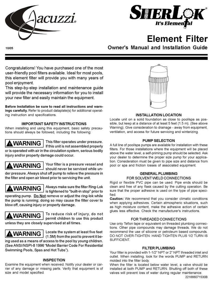
Element Filter System
Owner’s Manual and Installation Guide
221666071685B
Congratulations! You have purchased one
of the most user-friendly pool filter sys-
tems available. Ideal for above-ground
pools or in-ground vinyl liner pools, this
element filter system will provide you with
many years of pool enjoyment.
This step-by-step installation and mainte-
nance guide will provide the necessary in-
formation for you to install your new pool
system and easily maintain the equipment.
Risk of hair and/or body
entrapment! This system can
create high suction vacuum and should be installed with appropriate
vacuum release skimmers or multiple suction fittings or both.
Always make sure the filter Ring-
Lok is tightened to “built-in stop”
prior to operating pump. Do Not remove or adjust the Ring-Lok while
the pump is running; doing so may cause the filter cover to blow off,
causing injury or property damage.
To reduce risk of injury, do not
permit children to use this prod-
uct unless they are closely supervised at all times.
(For cord & plug connected units)
Risk of Electric Shock. Connect
only to a grounding type receptacle protected by a ground-fault cir-
cuit-interrupter (GFCI). Contact a qualified electrician if you cannot
verify that the receptacle is protected by a GFCI.
(For cord & plug connected units)
Do not bury cord. Locate cord
to minimize abuse from lawn mowers, hedge trimmers and other
equipment.
(For cord & plug connected units)
To reduce the risk of electric
shock, replace damaged cord immediately.
(For cord & plug connected units)
To reduce the risk of electric
shock, do not use an extension cord to connect unit to electric
supply; provide a properly located outlet.
Locate the system at least five
feet (1.5M) from the pool to pre-
vent it being used as a means of access to the pool by young chil-
dren. (See ANSI/NSPI-8 1996 “Model Barrier Code For Residential
Swimming Pools, Spas and Hot Tubs”).
This pump is for use with
permanently installed pools and
may also be used with hot tubs and spas if so marked. Do not use
with storable pools. A permanently installed pool is constructed in or
on the ground or in a building such that it cannot be readily disas-
sembled for storage. A storable pool is constructed so that it may be
readily disassembled for storage and reassembled to its original in-
tegrity.
To guard against low voltage
which can damage the pump mo-
tor, use minimum wire gauge. Shown below:
SAVE THESE INSTRUCTIONS.
WARNING
!
WARNING
!
WARNING
!
WARNING
!
WARNING
!
WARNING
!
WARNING
!
WARNING
!
CAUTION
!
CAUTION
!
6/05
Warns about hazards that CAN cause
serious personal injury and property
damage if ignored.
WARNING
!
Wire Length
HP 50 ft. 100 ft.
3/4 #14G #12G
1 #12G #10G
A) OPTIONAL SHUT-OFF VALVE B) BARBED ADAPTER
C) HOSE D) CLAMP
PUMP INLET
LOCATION OF SYSTEM:
1) Locate system on solid, level
foundation. 2) To reduce the risk
of electrical shock, install the
system at least 5 feet (1.5M)
from the pool. Give consider-
ation to any other local codes
that may apply. 3) System
should have adequate access
for future servicing and winter-
izing. 4) Provide for adequate
water drainage away from
equipment. 5) If you cover your
system, be certain to provide
adequate ventilation.
Step 1
Although optional, we recom-
mend shut-off valves (A) be in-
stalled in the pump inlet and
pool inlet fitting for easy servicing when the system is installed below the water level of the pool.
Step 2
Prepare hose adapters by wrapping threads with teflon tape. Install two hose adapters
(B) in the following locations: Pump Inlet (or optional shut-off valve) and Filter Outlet.
Step 3
Attach hose (C) using hose clamps (D) to male adapters (B) according to the diagram shown above.
Note: Refer to pool manufacturer’s installation instructions for more detail.
You are now ready to fill your pool and begin system start-up procedures.
AC
D
B
D
FILTER
OUTLET
SKIMMER
POOL
INLET
FITTING
D
C
D
BA
Standard 3-prong
plug
Refer to information on motor nameplate for electrical service data.
If the pump on your system is supplied with a 3-prong twist lock
115V plug, then the appropriate female receptacle should be in-
stalled. For systems with a standard 3-prong 115V plug, we
recommend a grounded receptacle be installed with a built-in
Ground Fault Circuit Interrupter (GFCI). Motors should have fused
disconnect switch or circuit breaker and wire size large enough for
pump horsepower and distance from power source. Wiring should
be done in accordance with applicable codes by a competent elec-
trician.
Electrical Data:
3-prong
twist-lock plug
Typical above-ground pool connection:
2
Parts For Models SHER80 and 120:
FIG. NO. PART NO. DESCRIPTION
1
2
3
4
5
6
7
8
9
10
11
12
42-3671-02-R
42-3677-06-R
42-3677-06-R10
39-2547-01-R
39-2547-01-R50
47-0106-08-R
9193-4182-R
42-2852-05-R
42-2998-00-R
47-0380-47-R
42-3674-09-R
42-3675-08-R
42-3674-19-R
42-3675-18-R
42-2946-03-R
42-2947-02-R
42-3662-00-R
47-0228-01-R
43-3092-02-R
43-3091-03-R
Ring-Lok™
Cover latch
Cover latch (10 per bag)
Air bleed valve knob w/ O-ring
(50 per bag)
O-ring 3/16 x 3/8 x 3/32
Pressure gauge 0-60# 1/4 CBM
Cover - 80 sq. ft.
Cover - 120 sq. ft.
O-ring 11-1/2 x 11-7/8 x 3/16
Element assy. 80 sq. ft. 14.59 LG
Element assy. 120 sq. ft. 20.90 LG
Microban Element assy. 80 sq. ft.
Microban Element assy. 120 sq. ft.
Dirt catcher 80 sq. ft.
Dirt catcher 120 sq. ft.
SherLok 1-1/2 filter body
O-ring
Plug 2” w/ O-ring
Plug 1-1/2” w/ O-ring
What you should have - Filter system parts breakdown:
Tools you will need:
For most installations all you will
need are (a) screwdriver (b) wide
mouth pliers and (c) adjustable
wrench.
(a) (b) (c)
System to Pool 6’ Hose Kit (Included in
Systems with HK6 in Model Number).
Parts for System
Components: 9422-4052-R
9422-4060-R
12-1152-00-R
14-4340-96-R3
14-4020-02-R2
14-4273-06-R
47-0328-00-R
42-3632-00-R
47-0228-68-R
9402-2955
9402-2960
1
2
3
4
6
7
8
9
10
Element 80 Filter
Element 120 Filter
Base
P.L. Hex Capscrew 12-14 x 3/4” (3 per bag)
P.L. Hex Capscrew 14-10 x 3/4” (2 per bag)
Interconnect Nut
O-Ring 1-7/8 IC x 3/16 TK
Interconnect Pipe
O-Ring 1-7/8 ID x 3/16 TK
S1BU9-6 Pump
S15BU9-6 Pump
FIG NO. PART NO. DESCRIPTION
O-Ring
Step 1
Install threaded end of interconnect pipe
into the filter “INLET.” Tighten until O-ring
seals against filter.
NOTE: Be sure union nut is placed on
interconnect pipe before it is threaded
into filter. Threads on union nut should
face away from the filter.
Step 2
Note that there are three (3) “notches”
cut out of the bottom of the filter. Note
also that there are three (3) raised
“blocks” on the inner circle of the base.
Place the filter onto the base with the in-
terconnect pipe facing towards the pump
mount “pedestals”. Press down and ro-
tate as necessary until the “notches” on
the bottom of the filter engage with the
“blocks” on the base. The filter will drop
Notches Blocks
Interconnect
pipe
Cutout
Setting up your system:
down and lock into place. Locate the three (3) large “cutouts” around the perimeter
of the base where the filter inserts into the base. Look into the “cutouts” and locate
the 1” slots molded into the base. The pre-drilled holes at the bottom of the filter
should line up with the 1” slots in the base. Attach filter to base with the three (3)
12-14 x 3/4” screws provided.
Step 4
Position the pump on the base “pedes-
tals” with the pump strainer basket over
the strainer support pedestal as shown.
Connect the union nut on the intercon-
nect pipe to the pump discharge and
hand-tighten only.
Using the two (2) 14-10 x 3/4” screws
supplied, locate the predrilled holes on
the “pedestals” and secure pump to the
base.
Step 5
Be certain that the filter cover is pushed
completely down and the Ring-Lok nut is
tightened to the “built-in stops” and yel-
low safety latch is engaged.
Step 6
Carefully install the pressure gauge into
the filter cover after wrapping the brass
threads with 4 wraps of teflon tape
Note: Some gauges have teflon tape fac-
tory installed.TIP: Install pressure gauge
only hand-tight plus 1/4 turn.
O-Ring
Motor Mount
Pedestals
Strainer Support
Pedestal
If the Ring-Lok nut is not
tightened so yellow
safety latch is engaged,
the filter cover may blow
off causing injury or
property damage.
FILTER
Nut
Step 3
Be sure that the O-ring is firmly seated in
the O-ring groove in the end of the inter-
connect pipe.
System start-up:
CAUTION: Water acts as a coolant for the seal. Do not operate your pump until it has been filled with water (primed).
For above-ground pools with system below the pool water level:
Step 1
Open the air bleed valve on top of the
filter to allow captured air to escape.
When a steady stream of water appears,
close valve. NOTE: If optional shut-off
valves are installed, be sure that both
valves are fully opened.
Step 2
Turn the motor on by plugging
the unit into a grounded electri-
cal receptacle.
DO NOT USE AN
EXTENSION CORD.
Step 3
Open air bleed valve to release any ad-
ditional trapped air. When a steady
stream of water appears, close the valve.
Step 4
The filter is equipped with a pressure
gauge to assist in determining when the
filter element should be cleaned. Note
gauge reading when filter is started up,
“CLEAN.” As the filter becomes dirty, the
needle will move to the right. When the
needle has moved 6-8 psi above the
“CLEAN” reading, the filter element
Air bleed
valve
Air bleed
valve
Place the cover on the filter body and
press firmly downward until the cover
comes to a stop against the filter body.
TIP: It is easier to replace the filter cover
if the air bleed valve is open.
Step 7
Remove the cover by inserting Ring-Lok
tab into slot and rotating Ring-Lok until
cover is separated from filter body. You
may also remove it by pulling upward on
handles while rocking cover.
Step 8
Grasp the handle and lift element out of
the filter tank, leaving the support tube in
the filter tank. If support tube comes out
with element, remove it from element and
press it back into filter tank ensuring that
it is pressed all the way in. Also, wash
Step 9
Clean the element with a high pressure
nozzle on a garden hose. Place the
nozzle inside the element and spray out-
ward pushing any trapped debris out of
the element.
Step 10
Clean the O-ring on the filter body and
relubricate with petroleum jelly. Also,
clean all surfaces that come in contact
with the O-ring to assure a good seal.
Install O-ring on filter body.
Step 6
Press down on filter yellow safety tab lock
and rotate the large Ring-Lok nut
counter-clockwise. Using both hands
continue to unscrew Ring-Lok nut and
remove. Ring-Lok nut has tabs located
around its perimeter that may be used to
help separate cover from the body.
Step 11
Place the element back into the filter tank,
making sure that it is seated securely
onto support tube.
Step 3
Unscrew the strainer Ring-Lok nut and
remove the clear strainer cover.
CAUTION: Some remaining water may
spill out of the strainer body when the
clear strainer cover is removed.
Lift the basket out of the strainer and re-
move the debris. Reinstall the basket.
Step 4
Clean the O-ring on the clear strainer lid
and re-lubricate with petroleum jelly. Also,
clean all surfaces that come in contact
with the O-ring to assure a good seal.
Step 5
Replace the clear cover and strainer
Ring-Lok HAND-TIGHTEN ONLY. Open
the optional valves if installed.
If you do not want to clean the filter ele-
ment, skip to the end of this section.
To avoid electrical shock, unplug the pump
before performing any service or maintenance.
If filter Ring-Lok is removed or adjusted under pressure, the filter cover may
blow off, causing injury or major property damage.
Step 2
Drain filter tank by first removing the drain
cap and then opening air bleed valve. Re-
place the drain cap once filter is drained.
If you do not want to clean the strainer,
skip to Step 6.
Open air bleed
valve second
Remove drain
cap first
WARNING
!
out any debris remaining in the filter tank and replace drain cap. TIP: For optimum
cleaning, allow your element to dry. Brush off the remaining dirt and chemicals that
will not wash off with the hose. An additional element will allow you uninterrupted
enjoyment of your pool during this cleaning procedure.
Step 12
Clean the threads of Ring-Lok nut and
the threads on filter body with water or
a cloth. Place Ring-Lok nut on filter and tighten to the
“built-in stops.” Be sure yellow safety latch is engaged.
Unplug the pump cord.
Step 1
For above-ground pools with the filter system located below the pool
water level: Your system is full of water. If you remove the pump strainer
cover, water will run out freely from your pool. You must close the
shut-off valves, if installed, or make provisions to stop the flow of
water from your pool.
STOP
Cleaning the pump strainer or filter element:
If the Ring-Lok nut is not tightened so yellow safety latch is engaged, the
filter cover may blow off causing injury or property damage.
3
You are now ready to perform the system start-up.
should be removed and cleaned. See “Cleaning the pump strainer or filter ele-
ment.”
Remove strainer
cover
Clean strainer
basket
Inside surface
O-Ring
O-Ring groove
Place element into
filter tank
Place cover on
filter body
OR CONSEQUENTIAL DAMAGES. Some US states or Canadian provinces do not allow the
exclusion or limitation of incidental or consequential damages, so the above may not apply to you.
This warranty applies to products used in swimming pool, spa, & aquaculture applications only and does
not apply to any product which has been subjected to negligence, alteration, accident, abuse, misuse,
improper installation, abrasives, corrosion and/or electrolysis, improper voltage supply, vandalism, civil
disturbances, or acts of God (including but not limited to freeze damage, lightening strikes, and other
damage caused by catastrophic events). The only warranties authorized by CPP are those set forth herein.
CPP does not authorize other persons to extend any warranties with respect to its products, nor will CPP
assume liability for any unauthorized warranties made in connection with the sale of its products. The
Company will not be responsible for any statements that are made or published, written or oral, which are
misleading or inconsistent with the facts as published in the literature or specifications furnished by the
Company.
WARRANTY CLAIM PROCEDURE
Warranty claims shall be made by contacting the installing/selling, builder, dealer, or retailer (point of
purchase) or the Jacuzzi pool products distributor in your area. All equipment must be inspected by a local
Company representative or at the factory before warranty is authorized. All charges or expenses for freight
to and from the factory, removal and reinstallation of the products, or installation of a replacement product
are the responsibility of the purchaser unless otherwise expressly authorized by Cantar Pool Products.The
Company, at its discretion, may repair or replace free of charge (F.O.B. factory in Toronto, Ontario) any
product that proves defective within the warranty period, or it may issue credit in the amount of the invoice
of the defective equipment in lieu of repair or replacement. The Company reserves the right to substitute
new or improved equipment on any replacements. The provisions of this additional written warranty are
in addition to and not a modification of or subtraction from the statutory warranties and other rights and
remedies provided by any US state or Canadian provincial law.
JACUZZI POOL PRODUCTS - Limited Warranty
Cantar Pool Products (the Company or CPP) warrants Jacuzzi pool products to be free of defects in
material and workmanship for a period of 36 months from the date of purchase or 48 months from the date
of manufacture, whichever comes first, with the following exceptions:
Shaft Seals - For all pumps with Jacuzzi’s patented “dry-run” heat sink, the shaft seal carries an
unconditional warranty against damage or failure for 2 years from date of purchase/installation.
Light Bulbs - FullMoon Watercolor LED light bulbs are warranted for 1 year from date of purchase;
incandescent bulbs are warranted for 90 days from date of purchase.
Misc. - Filter elements, DE grids, white-goods, strainer baskets, strainer basket “flap” and “priming tube”,
pressure gauges, square rings, o-rings, gaskets, and all replacement parts are warranted for 1 year from
the date of purchase.
In order to activate this 3-year warranty, Jacuzzi products may be registered with Cantar Pool
Products by either of the following methods:
•Mail-in Warranty Registration Card •Online at www.cantar.com
This warranty extends only to the original retail purchaser and only during the time in which the original retail
purchaser occupies the site where the product was originally installed. CPP’s warranty obligation with
regard to equipment not of its own manufacture is limited to the warranty actually extended to CPP by its
suppliers.
THIS WARRANTY IS EFFECTIVE January 1, 2005. ANY IMPLIED WARRANTIES WHICH THE
PURCHASER MAY HAVE, INCLUDING MERCHANTABILITY AND FITNESS FOR A PARTICULAR
PURPOSE, SHALL NOT EXTEND BEYOND THE APPLICABLE WARRANTY PERIOD. Some US
states or Canadian provinces do not allow limitations on how long an implied warranty lasts, so
the above limitation may not apply to you. IN NO EVENT SHALL CPP BE LIABLE FOR INCIDENTAL
Manufacturer’s Warranty:
4
WARNING
!Disconnect power to motor main circuit
breaker to avoid electrical shock. If filter Ring-
Lok is removed or adjusted under pressure, the filter cover may blow off, caus-
ing injury or major property damage.
EXCESSIVE NOISE COMING FROM PUMP OR MOTOR.
The basket in the skimmer or the lint strainer may be clogged; The motor bearing may be worn out;
Valve in suction line may be partly closed; Suction line may be partly plugged; The vacuum hose may
be plugged or too small; The pump may not be supported properly.
WATER LEAKS FROM SHAFT.
Shaft seal requires replacement.
FILTER TANK LEAKS WATER.
Split in tank due to freeze or other damage. Replace; Lid O-ring damaged, twisted, or not lubricated.
Inspect; Lock ring to lid not tight. Inspect and tighten down to engage lock tabs; Air bleed valve loose or
O-ring missing. Inspect; Inlet/outlet fittings loose or not sealed. Inspect.
DEBRIS BACK TO POOL.
Dirty filter. Clean element in filter cleaner or replace; Cracked dirt catcher. Inspect and replace if neces-
sary; Filter collapsing. By-pass through top of dirt catcher. Inspect or replace; Holes in filter. Replace;
Filter isn’t sealed in dirt catcher. Inspect; Filter is installed upside down. Install top-side up. Inspect.
FILTER DOESN’T KEEP WATER CLEAN.
Fitler collapsing. By-pass through top of dirt catcher. Inspect or replace; Holes in filter. Inspect or replace;
Filter installed upside down. Inspect or install top-side up; Filter isn’t seated in dirt catcher. Inspect;
Water started out dirty. Continue to filter and clean as necessary; Heavy swimmer load. Clean filter as
necessary; Flow rate too low. Increase flow to turn water more often.
PRESSURE DOESN’T DROP IN FILTER AFTER CLEANING.
Dirty filter. Clean element in filter cleaner or replace; Gate valve closed in return line. Inspect; Return line
partially clogged. Inspect; Return fitting clogged. Inspect.
TANK WILL NOT ALIGN WITH BASE MOUNTING HOSES.
Check position of tank; Rotate; Loosen pump from base to allow filter to move and align.
FILTER LID LEAKING.
Inspect O-ring, cracks, twisted. Replace; Lid cracked. Replace; Tank cracked. Replace.
SERVICE & REPAIR PARTS
Refer all sevice to your local dealer. Order all repair parts through your dealer. Give the following informa-
tion when ordering repair parts: Unit nameplate information and description of part. If the recommenda-
tions in the “Trouble Shooting” portion of this manual do not solve your particular problem please contact
your local dealer for service.
THE MOTOR DOES NOT START WHEN YOU PLUG IT IN.
The disconnect switch or the circut breaker is in the OFF position; Fuses may be blown or the thermal
overload is open; Motor shaft is locked; Motor windings are burned out; A defective starting switch
inside the single-phase motor; Wiring may be disconnected or defective; Low voltage in outlet.
THE MOTOR DOES NOT REACH ITS FULL SPEED.
Low voltage; Two-speed model set on low speed; Motor windings connected for wrong voltage on dual
voltage model.
THE MOTOR OVERHEATS AND THE PROTECTOR TRIPS.
Low voltage; Inadequate ventilation; Motor windings connected for wrong voltage on dual voltage model.
NO WATER IS DELIVERED BY PUMP.
Pump is not primed; Closed valve in suction or discharge line; Leakage of air into the suction system;
Impeller clogged.
AIR BUBBLES APPEAR AT INLET FITTINGS.
Air may be leaking into the suction line at the connections or valve stem; Cover gasket or lint strainer
may need cleaning; Restriction in suction line or low water level in pool.
LOW CAPACITY WHEN PUMP IS TURNED ON.
Valve in suction or discharge line is partly closed; Suction or discharge line is partly plugged; Suction or
discharge line is too small; The basket in the skimmer or the lint strainer may be clogged; The filter may
be dirty or the impeller may be clogged.
LOW PRESSURE WHEN PUMP IS TURNED ON.
The discharge valve or inlet fittings may be open too wide.
HIGH PRESSURE WHEN PUMP IS TURNED ON.
The discharge valve or inlet fittings may be closed too much.
Step 3
Drain pump strainer and pump case by loosening the
plugs shown. The pump will drain without completely
removing the plugs from the pump. NOTE: If tempera-
tures in the winter are severe, you may choose to dis-
connect your filter system from the pool and move it to
a protected area.
Drain
plugs
Winterizing the filter system and water maintenance:
To avoid electrical shock, unplug the pump before performing any service or maintenance. If filter Ring-Lok is removed
or adjusted under pressure, the filter cover may blow off, causing injury or major property damage.
WARNING
!
Water maintenance:
A proper and consistent use of chemicals is necessary
to maintain clean, sanitary water, to prevent a spread
of germ infection and control the growth of algae which
can spoil the appearance and enjoyment of your pool
or spa. See your pool professional for proper chemical
maintenance.
Trouble Shooting:
Unplug the pump cord.
Step 2
Drain the filter tank by first removing the
drain cap and then opening the air bleed
valve. Replace the drain cap once filter is
drained.
Step 1
For above-ground pools with the filter system located below the pool
water level: You must drain the water in the pool below the skimmer
and inlet fitting. Follow pool manufacturer’s recommendations for
winterizing the pool. Your system is full of water.
STOP
Open air bleed
valve second
Remove drain
cap first
In Canada 325 Humber College Blvd. Toronto, ON, M9W 7C3 Phone: 800.836.1210 Fax: 416.798.2801
In USA 1515 S. Bowman Rd., Suite A Little Rock, AR 72211 Phone: 866.370.2664 Fax: 800.447.3181
CANTARCANTAR
CANTARCANTAR
CANTAR Pool Products Ltd.Pool Products Ltd.
Pool Products Ltd.Pool Products Ltd.
Pool Products Ltd.
Produits de Piscine Ltée.Produits de Piscine Ltée.
Produits de Piscine Ltée.
Jacuzzi is a registered trademark of Jacuzzi Inc. and used under license.
R
This manual suits for next models

1

Other Jacuzzi Swimming Pool Filter manuals

Jacuzzi L160C Programming manual

Jacuzzi

Jacuzzi L160C Programming manual

Jacuzzi JMC16 User manual

Jacuzzi

Jacuzzi JMC16 User manual

Jacuzzi COMMANDER III JC13 User manual

Jacuzzi

Jacuzzi COMMANDER III JC13 User manual

Jacuzzi COMMANDER III JC7 User manual

Jacuzzi

Jacuzzi COMMANDER III JC7 User manual

Jacuzzi SHER80 Programming manual

Jacuzzi

Jacuzzi SHER80 Programming manual

Jacuzzi SHER80 Programming manual

Jacuzzi

Jacuzzi SHER80 Programming manual

Jacuzzi L140C User manual

Jacuzzi

Jacuzzi L140C User manual

Jacuzzi COMMANDER II JC5 User manual

Jacuzzi

Jacuzzi COMMANDER II JC5 User manual

Jacuzzi Avalanche Programming manual

Jacuzzi

Jacuzzi Avalanche Programming manual

Popular Swimming Pool Filter manuals by other brands

STA-RITE System 2 owner's manual

STA-RITE

STA-RITE System 2 owner's manual

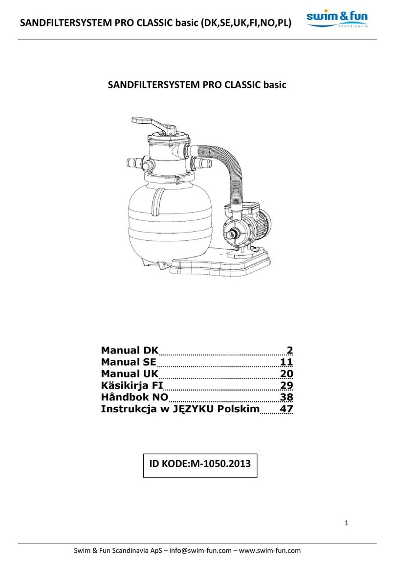
Swim & Fun PRO CLASSIC basic manual

Swim & Fun

Swim & Fun PRO CLASSIC basic manual

Behncke B075 instruction manual

Behncke

Behncke B075 instruction manual

JNS Aquaria VS-1.5 installation guide

JNS Aquaria

JNS Aquaria VS-1.5 installation guide

ChlorKing NEXGEN40 Installation, operation and maintenance manual

ChlorKing

ChlorKing NEXGEN40 Installation, operation and maintenance manual

BSV BS POOL PRO Series user manual

BSV

BSV BS POOL PRO Series user manual

Pool Technologie Minisalt NPS 4 Instructions for use

Pool Technologie

Pool Technologie Minisalt NPS 4 Instructions for use

ChlorKing NEXGEN60 Installation, operation and maintenance manual

ChlorKing

ChlorKing NEXGEN60 Installation, operation and maintenance manual

MARIMEX ProStar 2 manual

MARIMEX

MARIMEX ProStar 2 manual

Evolution Aqua NEXUS 220 Installation and instruction manual

Evolution Aqua

Evolution Aqua NEXUS 220 Installation and instruction manual

Jandy DEL Series Filters Installation and operation manual

Jandy

Jandy DEL Series Filters Installation and operation manual

JNS Aquaria Sigma-1 quick start guide

JNS Aquaria

JNS Aquaria Sigma-1 quick start guide

Lomart Deluxe Thru-Wall Skimmer 1-4113-006 owner's guide

Lomart

Lomart Deluxe Thru-Wall Skimmer 1-4113-006 owner's guide

Majestic UNO Instructions for use

Majestic

Majestic UNO Instructions for use

HEISSNER F540-00 Instructions for use

HEISSNER

HEISSNER F540-00 Instructions for use

Pentair STA-RITE PLM100 owner's manual

Pentair

Pentair STA-RITE PLM100 owner's manual

Hayward SandMaster SM1700T Series owner's manual

Hayward

Hayward SandMaster SM1700T Series owner's manual

TeichTip SUNSUN CSP-250 Operation manual

TeichTip

TeichTip SUNSUN CSP-250 Operation manual

manuals.online logo
manuals.online logoBrands
  • About & Mission
  • Contact us
  • Privacy Policy
  • Terms and Conditions

Copyright 2025 Manuals.Online. All Rights Reserved.