Jands JLX-LITE-MkII User manual

Modular Lighting Bar System
JLX-LITE-MkII
USER GUIDE

COMPLIANCE
This product is approved for use in Australia/New Zealand
and conforms to the following standards.
Standards
AS/NZ 3100-2002 - Approval and test specification - General requirements for
electrical equipment
Disclaimer
Information contained in this user guide is subject to change without notice and
does not represent a commitment on the part of the vendor. JANDS Pty Ltd
shall not be liable for any loss or damage whatsoever arising from the use of
information or any error contained in this manual.
It is recommended that all service and repairs on this product be carried out by
JANDS Pty Ltd or its authorised service agents.
JANDS Theatre equipment must only be used for the purpose they were
intended by the manufacturer and in conjunction with this user guide.
JANDS Pty Ltd will not accept any liability whatsoever for any loss or damage
caused by service, maintenance or repair by unauthorised personnel, or by use
other than that intended by the manufacturer.
Manufactured in Australia by
JANDS PTY LTD ABN 45 001 187 837
Head Office: 40 Kent Road, Mascot NSW 2020. Sydney, Australia.
Postal Address: Locked Bag 15, Mascot NSW 1460. Sydney, Australia.
P: (+61) 2 9582 0909 F: (+61) 2 9582 0999
W: www.jands.com.au E: [email protected]
JANDS PTY LTD 2015 All rights reserved.
Revision 1.0
3 March 2015

USG-00000-JLXLITEMKII [1.0]
JLX LITE MKII
1
TABLE OF CONTENTS
1INTRODUCTION..........................................................................2
1.1 Mounting Options .................................................................................2
1.2 Layout...................................................................................................2
2INSTALLATION............................................................................3
2.1 Initial Inspection....................................................................................3
2.2 Planning - Mechanical..........................................................................3
2.3 Planning - Electrical..............................................................................4
2.4 Installation............................................................................................4
2.5 Perch Bar (Vertical) Installation............................................................6
2.6 Installation Record................................................................................8
3INSPECTION & MAINTENANCE.................................................9
3.1 Annual Equipment Inspection/Maintenance Log ................................10
4TECHNICAL DATA AND SPECIFICATIONS.............................. 11
4.1 Rated Capacity...................................................................................12
4.1.1 Definitions of Load.................................................................. 12
4.1.2 Maximum Point Load.............................................................. 12
4.1.3 Maximum Uniformly Distributed Load (UDL)........................... 12
4.2 Mounting Hole Detail..........................................................................13

USG-00000-JLXLITEMKII [1.0]
JLX LITE MKII
2
1INTRODUCTION
The Jands JLX-LITE-MkII is a universal modular wired bar system intended for fixed installations where
a lighting bar with associated fixed wiring is required.
1.1 Mounting Options
The JLX-LITE-MkII includes many mounting holes on its top surface and is intended to be mounted is
number of different ways, including:
Surface mounted to ceiling
On a surface mounted frame
Suspended from threaded rods
Vertical mounting as a Perch Bar
The Jands JLX-LITE-MkII is suitable for fixed indoor applications only, and is not protected against the
ingress of moisture.
The JLX-LITE-MkII is not rated as a lifting bar under AS4991.
The JLX-LITE-MkII is supplied unwired and the wiring should be installed by a licensed electrician.
1.2 Layout
Figure 1 –Component identification
Multiple fixing keyholes
Cable knock-outs in the top and end faces
Removable dress covers
Base
Bar
Bar Hangers

USG-00000-JLXLITEMKII [1.0]
JLX LITE MKII
3
2INSTALLATION
2.1 Initial Inspection
The Jands JLX-LITE-MkII Lighting bar should be inspected prior to installation. Any dents, cracks or
damage that appears to have been suffered in transit should be photographed and the freight company
notified before proceeding.
2.2 Planning - Mechanical
The Jands JLX-LITE-MkII should be installed by persons familiar with the installation of load bearing
structures.
WARNING
Failure to correctly install the JLX-LITE-MkII may
result in injury or death
The JLX-LITE-MkII has been designed to be mounted in various ways depending on the building struc-
ture it is being mounted to. Fixing methods include, but are not limited to:
Direct to a concrete slab using chemical or expanding anchors.
Direct into ceiling joists using timber screws, possibly through an intermediate layer of plaster-
board.
Suspended using droppers.
Into another supporting structure using nuts and bolts. Note mounting to suspended ceiling is
not recommended as these are generally not strong enough to support the required load. If the
JLX-LITE-MkII must be mounted against a suspended ceiling it should be mounted to the struc-
ture above the ceiling using droppers.
Fixed using standard strut or other additional dedicated structure mounted either along the bar
or preferably perpendicular to the bar. for example surface mounted standard strut.
Do not mount the JLX-LITE-MkII using plasterboard fasteners of any kind - the JLX-LITE-MkII must be
fixed to a solid structure.
When locating the fixings, plan the layout so that:
there is at least one substantial fixing for example masonry anchor, per bar support i.e. for a
2.4m JLX-LITE-MkII use at least 4 substantial fixings; for a 1.6 m JLX-LITE-MkII use at least 3
substantial fixings. When using less substantial fixings, for example wood screws, use at least
twice the number of fixings and distribute them as evenly across the base as possible.
the fixings are located as close as practical to the bar supports.
if mounting the JLX-LITE-MkII to strut, ensure that the strut is fixed to the structure on either
side of the JLX-LITE-MkII i.e. the strut is not cantilevered.
when installed the mounting face of the duct will be within about 6 degrees of horizontal in both
lengthwise and crosswise directions. If this cannot be achieved in the lengthwise direction, use

USG-00000-JLXLITEMKII [1.0]
JLX LITE MKII
4
a Perch Bar option. If this cannot be achieved in the crosswise direction, consider a different
layout or using packing pieces to ensure the specification can be met.
During assembly:
If necessary drill holes into the base of the JLX-LITE-MkII as required.
Use 20mm (minimum diameter) mud washers under the head of each fixing.
If using Nylocks ensure the thread is fully engaged in the nylon. If Nylocks are not used, use
lock washers under each nut.
Wall plugs should not be used.
The mains outlets are available on one side of the base only. It is recommended the mains out-
let side of the bar face away from the audience view if possible.
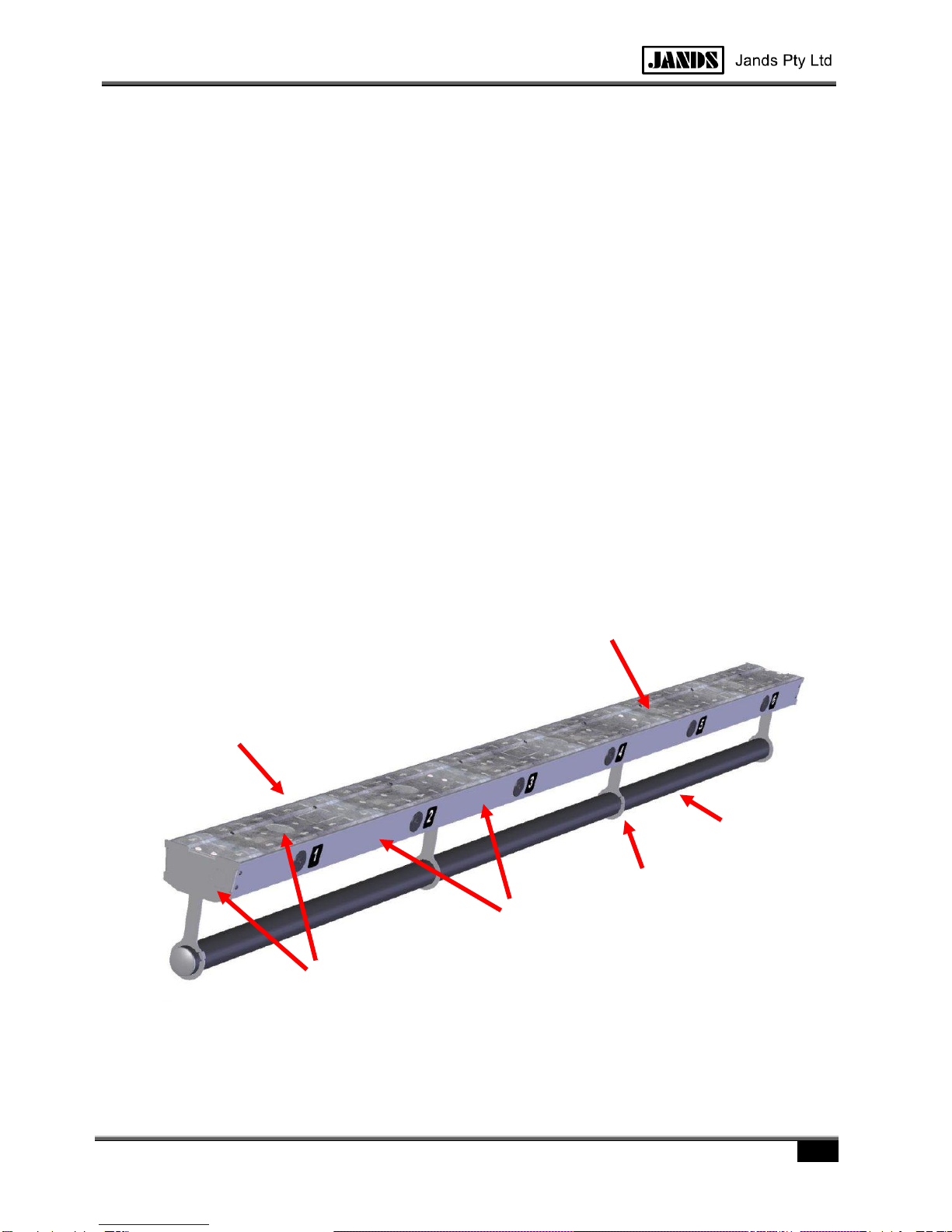
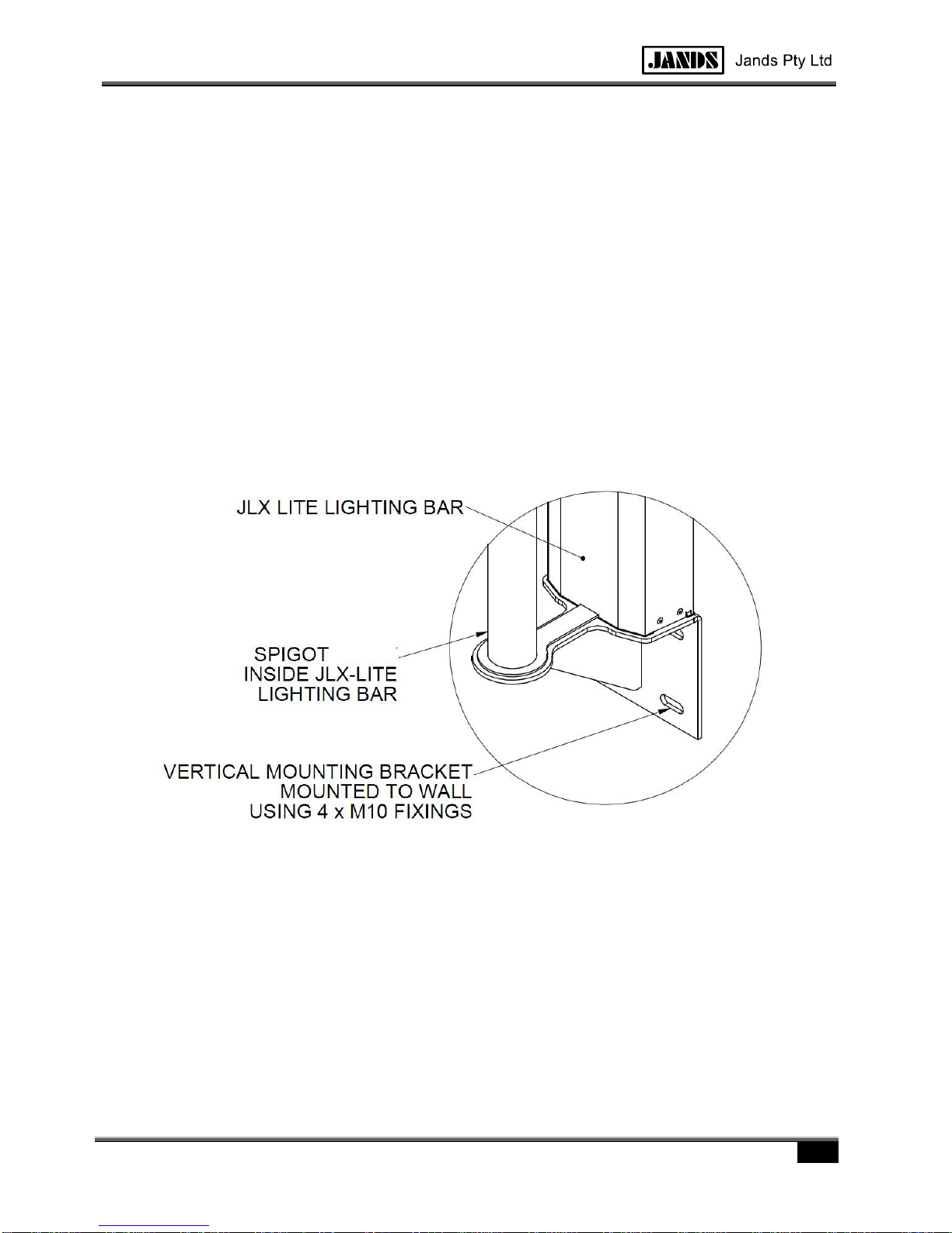
Two or more JLX-LITE-MkIIs may be mounted end to end to create one longer bar. A single joining
spigot is supplied with each JLX-LITE-MkII to end-align these bars. The spigot is not intended to carry
any significant load and should not be used in lieu of fixings in the base.
2.3 Planning - Electrical
The JLX-LITE-MkII is supplied with unwired/loose mains sockets that can be configured during installa-
tion. Some options include:
One circuit for all outlets. This is more suited to small installations or where no dimming is re-
quired - the outlets are used to power non-dim equipment such as LED fixtures and moving
lights.
Each supply circuit feeding a small number of outlets - for example one circuit feeding two out-
lets. Circuits may run direct to a switchboard or to a patch panel if dimming may be required.
This is suited to intermediate installations.
Individual circuits wired to a patch panel. This is the most flexible arrangement allows circuits to
be used as dimmers or direct power at will.
The mains outlets are available on one side of the base only. It is recommended the mains outlet side of
the bar face away from the audience view.
The JLX-LITE-MkII includes a number of knockouts and holes in the mounting face and ends of the
base. If the wiring can be planned before mounting it will be easier to remove the required knockouts
while the JLX-LITE-MkIIs are on the floor, prior to mounting. If the wiring hasn't been planned or there is
doubt about the how it will be done, they should be left in place for removal by the Electrician during in-
stallation.
2.4 Installation
The following is the installation procedure for horizontal bars. If mounting the JLX-LITE-MkII at an angle
greater than about 6 degrees lengthwise, use the Perch Bar option. Refer to section 2.5. It is intended
that the JLX-LITE-MkII be installed with the bar in place.
1. Install the supporting structure. See the available options and notes in section 2.2.
2. Remove the dress covers by removing the screw and sliding the cover along the bar enough so
it can be angled out of the available gap between the bar supports. Put the covers and screws
to the side with the other supplied accessories

USG-00000-JLXLITEMKII [1.0]
JLX LITE MKII
5
3. Depending on the required configuration it may be possible to install some of the wiring before
the bar has been hung. If this is the case, install any wiring that can be installed now.
4. Orient the bar as it is intended to be hung, checking the mains outlets are on the required side.
5. If two or more bars are to be mounted end to end, the supplied joining spigot is used to ensure
the bars align. Place the spigot against the end of the bar and rotate it so that the slots align
with the hanger screws as shown in Figure 2. When it's aligned, lightly tap the spigot into the
end of the bar with a mallet until it stops, about half way in.
Figure 2 Showing spigot slot aligned with hanger screw prior to insertion
6. Fix the first JLX-LITE-MkII base to the supporting structure, checking the orientation of the
mains outlets.
7. Install the remaining bases. If two or more bars are to be mounted end to end, ensure the join-
ing spigots are properly engaged before inserting the fixings. As each base is installed check
the mains outlets are on the correct side.
8. Run and terminate the mains wiring. The Jands JLX-LITE-MkII is supplied as a wiring enclosure
for installation by a licensed electrician to AS/NZS 3000 - wire links are supplied to earth the
socket outlets to a nearby tab on the chassis. Bend the tabs inwards before fitting the earth link
wire.
9. If using the ELV compartment, run and terminate the low voltage wiring, then fit / wire the con-
nectors.
10. Check the Earth continuity of all external parts and the socket outlet Earths.
11. Test the wiring as required by AS/NZS 3000.
12. Load test the bar.
13. Check the fixings are all in-tact and none have significantly deformed as a result of the load
test. At the same time double check all fasteners are secure and are using load spreading
washers. Also check there is an adequate quantity of fasteners (minimum one per bar hanger)
and the distribution of the fixings is even across the base/s. If necessary, add more fixings.
14. Cable tie the mains cable to the anchor points provided.
15. Cover any unused low voltage ELV connector knockouts with the supplied blank stick-on labels,
and similarly apply the numerical labels next to the mains sockets. Apply the numbers so they'll
be able to be seen through the cut-out in the dress cover when fitted - use the earth tab next to
Spigot Slot
Hanger Screw

USG-00000-JLXLITEMKII [1.0]
JLX LITE MKII
6
the socket as a locating guide. Unused mains socket holes must be protected with a metal
cover.
16. Remove the clear protective coating from the covers.
17. Fit the covers. The covers must be secured using the screws provided.
18. Fit the supplied end plugs to any open ends of the bar.
19. Fill out the installation record.
2.5 Perch Bar (Vertical) Installation
The JLX-LITE-MKII is not designed to resist significant end loads. A Perch Bar option allows the JLX-
LITE-MkII to be mounted so the bar is on its end (90 degrees from horizontal) for Perch or Box Boom
locations, but may also be used where the bars are at other angles. The Perch Bar option should be
used any time the bar is more than a few degrees off horizontal as shown by a spirit level. Always
mount the Perch Bar option at the low end of the bar.
When correctly installed the Perch Bar option allows the JLX-LITE-MkII bar to be used at the rated
working load limit. Note at high bar angles the bar will transfer the bulk of the load to the supporting
structure via the Perch Bar mount at the bottom. Hence this mount must be well fixed to the supporting
structure using multiple solid anchors that include a high shear strength.
1. Install the supporting structure. See the available options and notes in section 2.2.
2. Install the lower Perch Bar mount. Use a minimum of 4 substantial fixings. Do not mount to plas-
terboard or use wall plugs.
3. Remove the JLX-LITE-MkII dress covers by removing the screw and sliding the cover along the
bar enough so it can be angled out of the available gap between the bar supports. Put the cov-
ers and screws to the side with the other supplied accessories.
4. Orient the bar as it is intended to be hung, checking the mains outlets are on the required side.
DUCT

USG-00000-JLXLITEMKII [1.0]
JLX LITE MKII
7
5. Depending on the required configuration it may be possible to install some of the wiring before
the bar has been hung. If this is the case, install any wiring that can be installed now.
6. Fit the JLX-LITE-MkII to the Perch Bar mount so that the bar slides over the integral spigot on
the mount. Ensure the bar slides all the way down and is resting against the mount. If the bar
does not rest against the mount, rectify the problem.
7. Fix the first JLX-LITE-MkII base to the supporting structure, checking the orientation of the
mains outlets.
8. If desired a second Perch Bar mount can be installed at the top of the bar to provide greater
stability.
9. Run and terminate the mains wiring. The Jands JLX-LITE-MkII is supplied as a wiring enclosure
for installation by a licensed electrician to AS/NZS 3000 - wire links are supplied to earth the
socket outlets to a nearby tab on the chassis. Bend the tabs inwards.
10. If using the ELV compartment, run and terminate the low voltage wiring, then fit / wire the con-
nectors.
11. Check the Earth continuity of all external parts and the socket outlet Earths.
12. Test the wiring as required by AS/NZS 3000.
13. Load test the bar.
14. Check the fixings are all in-tact and none have significantly deformed as a result of the load
test. At the same time double check all fasteners are secure and are using load spreading
washers. Also check there is an adequate quantity of fasteners (minimum one per bar hanger)
and the distribution of the fixings is even across the base/s. If necessary, add more fixings.
15. Cable tie the mains cable to the anchor points provided.
16. Cover any unused low voltage ELV connector knockouts with the supplied blank stick-on labels,
and similarly apply the numerical labels next to the mains sockets. Apply the numbers so they'll
be able to be seen through the cut-out in the dress cover when fitted - use the earth tab next to
the socket as a locating guide. Unused mains socket holes must be protected with a metal
cover.
17. Remove the clear protective coating from the covers.
18. Fit the covers. The covers must be secured using the screws provided.
19. Fit the supplied end plugs to any open ends of the bar.
20. Fill out the installation record.

USG-00000-JLXLITEMKII [1.0]
JLX LITE MKII
8
2.6 Installation Record
This installation record should be filled out and signed by the person installing the lighting bar(s).
Where more than one person has installed the lighting bar(s), the foreman, supervisor or similar person
responsible for the works should fill out and sign this record.
Product
JANDS JLX-LITE-MkII
Number of Bars
Serial Number(s)
Project Name
Job No.
Installed By (Company)
Comments
Name
Signature
Date

USG-00000-JLXLITEMKII [1.0]
JLX LITE MKII
9
3INSPECTION & MAINTENANCE
The following page contains records for annual Inspection/maintenance. Inspection/Maintenance should
be carried out annually on both the mechanical structure and the electrical wiring etc by appropriately
qualified persons. Fill out the serial numbers for the inspection/maintenance logs, then copy the pages
for future use.
All the records should be kept for future reference.
WARNING
The JLX-LITE-MkII should be regularly inspected by an ap-
propriately qualified person/s

USG-00000-JLXLITEMKII [1.0]
JLX LITE MKII
10
3.1 Annual Equipment Inspection/Maintenance Log
Product
JLX-LITE-MkII
Serial Number (s)
Pass
Fail
Action
Inspect the chassis for evidence of impact damage or physical abuse
Inspect electrical outlets for evidence of wear and damage
Inspect mains cable and plugs for evidence of wear and damage
Inspect all screws, nuts, bolts for correct tightness and physical integrity
Inspect the visible portions of the central extrusion for distortion or cracks
Inspect attachment clamps, brackets and standoffs for distortion or damage
Perform safety tests (test & tag) to AS3760
Comments
Name
Signature
Test & Tag
Permit Number
Inspection Date

USG-00000-JLXLITEMKII [1.0]
JLX LITE MKII
11
4TECHNICAL DATA AND SPECIFICATIONS
PARAMETER
16M4
24M6
Number of Socket Outlets
4
6
Voltage
230V
Current
10A per outlet
Frequency
50Hz
ELV Connector hole
Suits Amphenol & Neutrik “D“ series
Maximum Point Load
50kg
Maximum Distributed Load (in-
cluding any point loads in a given
span) *
50kg/m
Working Load Limit *
100kg
150kg
Total Torsional Load on bar *
10Nm
15Nm
Bar Length
1600mm
2400mm
Depth
147mm
Height
207mm
Net Weight
9kg
12kg
Ingress Protection
IP2X
* Specification only valid when the top face of the duct is horizontal in both the crosswise and longitudinal directions. This specifi-
cation is reduced when the JLX-LITE-MKII is mounted at other angles.
Table 4.1 –Mechanical Specifications

USG-00000-JLXLITEMKII [1.0]
JLX LITE MKII
12
4.1 Rated Capacity
The load limitations of the JLX-LITE-MkII is outlined in the following sections. Note that the limits indi-
cated apply to JLX-LITE-MkII that has been installed as per the instructions in this guide.
WARNING
NEVER exceed the specified load rating
4.1.1 Definitions of Load
The "Working Load Limit" is the maximum overall load that the bar is permitted to carry. It is made up of
a combination of point loads and distributed loads.
4.1.2 Maximum Point Load
This is the maximum individual load that can be applied to a JLX-LITE-MkII. An example would be a
single light attached to the Bar.
Figure 4.1 –Point Load
In addition, the sum of all point loads between two bar hangers must not exceed the specified maxi-
mum.
4.1.3 Maximum Uniformly Distributed Load (UDL)
This is the maximum load that can be supported across a span of Bar. Include any point loads in the
calculation.
Figure 4.2 –Uniform Distributed Load (UDL)
1 metre

USG-00000-JLXLITEMKII [1.0]
JLX LITE MKII
13
4.2 Mounting Hole Detail
Table of contents
Other Jands Lighting Equipment manuals
Popular Lighting Equipment manuals by other brands

Stoane Lighting
Stoane Lighting inter-lux Niche Installation and maintenance instructions

GE
GE Evolve EWLS Series installation guide

Gama Sonic
Gama Sonic GS-4A instruction manual

Piscines Magiline
Piscines Magiline FX30 installation manual

THORLABS
THORLABS MCWHF2 quick start guide

LMI Technologies
LMI Technologies Gocator 2375 user manual

Hayward
Hayward OmniLogic installation manual

Confer Plastics
Confer Plastics ROLLGUARD 7200 ASSEMBLY, INSTALLATION AND USE MANUAL

BADU
BADU Genio Translation of the original operation manual

Chauvet
Chauvet Ovation F-145WW user manual

Telco
Telco SG 10 Series user manual

Lumi
Lumi WEDDING CAKE II Installation