Jands HP Series User manual

HP Series
Digitally Controlled Dimmer Rack
OOPERATING MANUAL

Contents i
Revision 2 - 20 March, 1997 HP SERIES DIMMER OPERATING MANUAL
EMC COMPLIANCE
This product is approved for use in Europe and Australia/New Zealand and conforms to the following standards:
European Norms Australian / New Zealand
Standards
EN 50081-1 AS/NZS 4252.1
EN 50082-1 AS/NZS 4251.1
EN 60950 AS/NZS 3260
To ensure continued compliance with EMC Directive 89/336 and the Australian Radiocommunications Act 1992, use
only high quality data cables with continuous shield, and connectors with conductive backshells. Examples of such
cables are:
DMX: Belden 8102 100% Aluminium foil screen, 65% Copper braid.
JANDS ELECTRONICS PTY LTD 1997
All rights reserved
DISCLAIMER
Information contained in this manual is subject to change without notice and does
not represent a commitment on the part of the vendor. JANDS ELECTRONICS P/L
shall not be liable for any loss or damage whatsoever arising from the use of
information or any error contained in this manual.
It is recommended that all service and repairs on this product be carried out by
JANDS ELECTRONICS P/L or its authorised service agents.
JANDS HP Series dimmers must only be used for the purpose they were intended by
the manufacturer and in conjunction with this operating manual.
JANDS ELECTRONICS P/L cannot accept any liability whatsoever for any loss or
damage caused by service, maintenance or repair by unauthorised personnel, or by
use other than that intended by the manufacturer.
Manufactured in Australia by:
JANDS ELECTRONICS PTY LTD ACN 001 187 837
40 KENT RD
Locked Bag 15
MASCOT NSW 2020
AUSTRALIA
PHONE: +61-2-9582-0909
FAX: +61-2-9582-0999
EMAIL: [email protected]

Contents ii
Revision 2 - 20 March, 1997 HP SERIES DIMMER OPERATING MANUAL
Table of Contents
Table of Contents
1.0 Introduction
2.0 Equipment Description
2.1 Front panel layout...................................................................................................2-0
3.0 Getting Started
3.1 Connecting power...................................................................................................3-0
3.2 Connecting loads....................................................................................................3-1
3.3 Connecting DMX-512 input ...................................................................................3-1
3.4 Power-up sequence.................................................................................................3-2
4.0 Dimmer Operation
4.1 Menu structure .......................................................................................................4-0
4.1.1 ENTER....................................................................................................4-0
4.1.2 NORMAL................................................................................................4-0
4.1.3 CLEAR....................................................................................................4-0
4.1.4 MODE menu............................................................................................4-0
4.1.5 DMX CHannel menu ...............................................................................4-5
4.1.6 DMX BANK menu..................................................................................4-6
4.1.7 BUILD menu ...........................................................................................4-6
4.1.8 RUN menu...............................................................................................4-7
4.1.9 TEST function..........................................................................................4-9
4.2 Deep clear ..............................................................................................................4-9
4.3 Channel disable ....................................................................................................4-10
4.4 Software update....................................................................................................4-10

Contents iii
Revision 2 - 20 March, 1997 HP SERIES DIMMER OPERATING MANUAL
5.0 Fault Diagnosis
5.1 Protection...............................................................................................................5-0
5.1.1 Output protection .....................................................................................5-0
5.1.2 Thermal protection...................................................................................5-1
5.1.3 Supply Power fault protection ..................................................................5-1
5.2 Output faults...........................................................................................................5-2
5.3 Operating faults......................................................................................................5-2
5.4 DMX faults.............................................................................................................5-3
5.5 Phase fault indication..............................................................................................5-3
5.6 Cold lamp filaments................................................................................................5-3
5.7 Output Loads..........................................................................................................5-3
5.8 Fault finding guide..................................................................................................5-4
6.0 Installation
6.1 Rack mounting .......................................................................................................6-0
6.1.2 Mounting in racks 465mm deep ...............................................................6-0
6.1.2 Mounting in deep racks using the Extender brackets.................................6-1
6.1.3 Rack Mounting - Ventilation....................................................................6-2
6.2 Wall Mounting .......................................................................................................6-2
6.2.1 Wall Mounting Dimmers - In Racks.........................................................6-3
6.2.2 Wall Mounting Dimmers - Flush to Wall..................................................6-4
6.2.3 Wall Mounting Dimmers - Straddling Cable Trays...................................6-5
6.2.4 Wall Mounting Dimmers - Conduited Cable Entry...................................6-6
6.2.5 Wall Mounting Dimmers - Hung from Bar Hooks....................................6-7
6.2.6 Wall Mounting Dimmers - Patch Lead Option..........................................6-8
6.3 Mounting the dimmer to the bracket.......................................................................6-9
6.4 Wall Mounting Dimmers - Ventilation..................................................................6-10
7.0 Maintenance

Contents iv
Revision 2 - 20 March, 1997 HP SERIES DIMMER OPERATING MANUAL
8.0 Technical Data and Specifications
8.1 Multipin output connector pin-outs.........................................................................8-2
8.2 DMX connector pin-outs........................................................................................8-5
8.3 DMX bank allocations............................................................................................8-5
8.4 Mains wiring colour codes......................................................................................8-6
8.5 Internal Mains Wiring.............................................................................................8-6
8.5.1 Normal Three Phase plus Neutral Operation.............................................8-6
8.5.2 Single Phase Operation ............................................................................8-6
8.5.3 Delta Supply Operation............................................................................8-7
8.5.4 Operation in Europe.................................................................................8-7

Introduction 1-0
Revision 2 - 20 March, 1997 HP SERIES DIMMER OPERATING MANUAL
1.0 Introduction
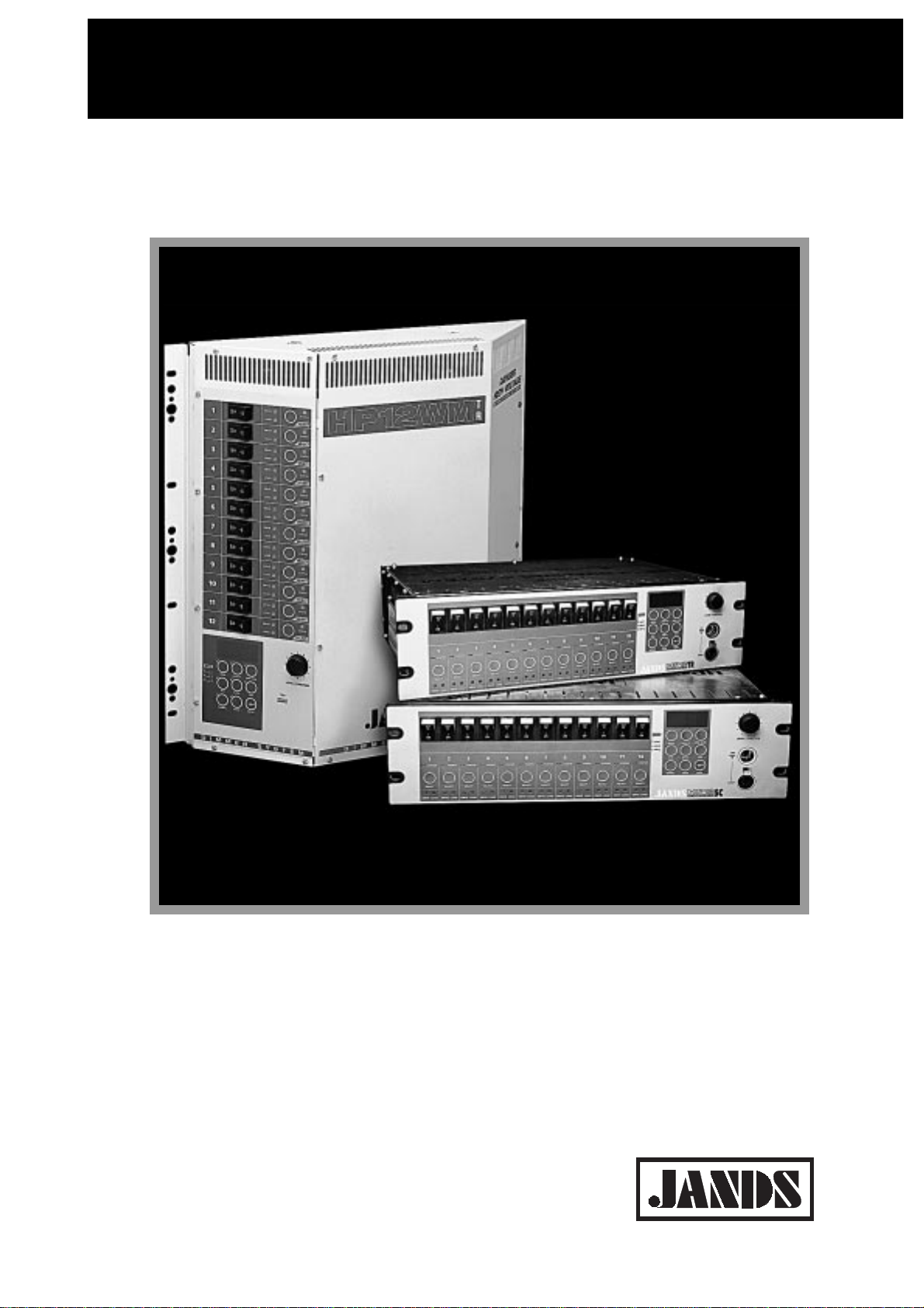
The JANDS HP12 series dimmers are rugged, high quality, 12 channel, 2.5kVA per
channel dimmers specifically designed for demanding touring and theatre
applications.
The HP12-TR features opto-controlled Triacs and medium risetime chokes; the HP12-
SC features DC-fired SCR pairs and high risetime chokes.
Complementing the HP12-TR / HP12-SC are the HP12-WMTR (wall-mounted Triac
dimmer) and the HP12-WMSC (wall-mounted SCR dimmer).
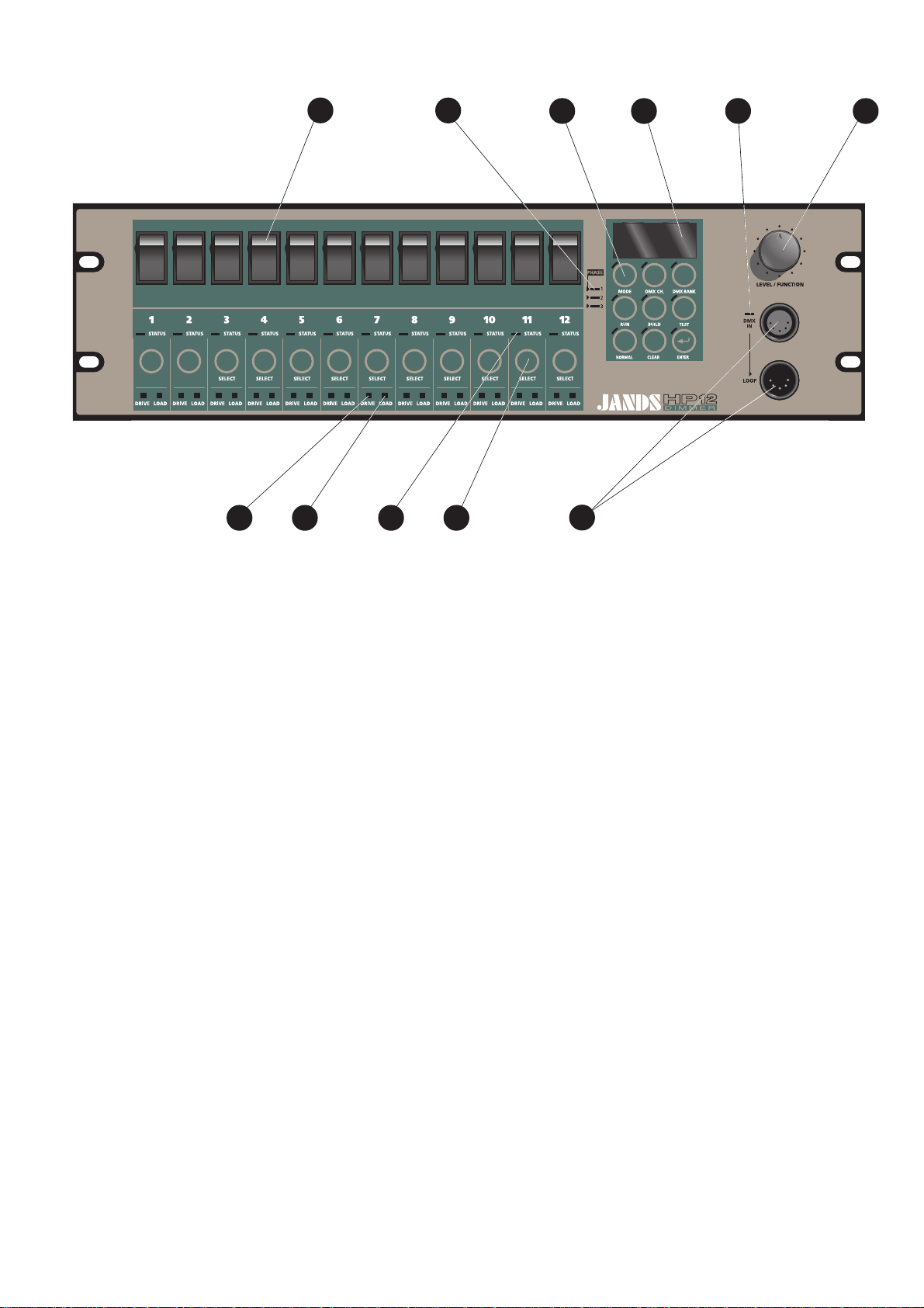
The HP12 series of dimmers feature microprocessor-based digital control. A keypad,
rotary encoder, channel switches, LED indicators and a large alphanumeric display
enable the user to monitor and select the built-in functions.
The user has the ability to select the DMX start number either by channel number or
in banks of 12 channels, test selected channels while the remainder of the dimmer
stays “on line”, select output voltage (eg. 120V) or ramp curves for designated
channels, capture up to three non-volatile DMX “snapshots”, build two user-definable
non-volatile scenes with the ability to import/select/set individual channel levels, and
to select from six “factory” built-in scenes including chases/random/crossfades. Other
functions also provided include dimmer “soft” start, channel-by-channel preheat
function, the ability to monitor the status of the dimmer rack in relation to supply
voltage, a bad (soft) neutral connection, over-temperature and other working
parameters of the unit.
The dimmer will “wake-up” in the mode it was last programmed to run - an ideal
function for stand alone applications. If no particular mode has been previously
defined, the dimmer rack looks for DMX control. If the rack loses DMX control at
any time while running, it defaults to the last received DMX command.
HP dimmers feature JANDS’ Ferrodipchokes. These chokes provide high rise time
along with excellent high frequency noise suppression and low acoustic noise.
The HP range of dimmers has been designed to allow for future optional upgrades to
the operating system.
Control signal to rack-mount dimmers is via a standard DMX-512 socket at either the
front panel or rear panel, while the dimmed outlets and three phase power entry are
located on the rear panel.
Control signal and three phase power entry to wall-mount dimmers are on internal
screw terminal blocks, while the dimmed outlets are on either internal screw terminal
blocks or front outlets (GPO's).
Bracket systems for the wall-mounted dimmers allow a wide variety of mounting
options - flush to the wall with rear wire entry, straddling cable trays, conduited
wiring from all four sides or mounted in standard rack frames and strips.

Introduction 1-1
Revision 2 - 20 March, 1997 HP SERIES DIMMER OPERATING MANUAL
Some key features of the dimmer range include:
FEATURE HP12-TR HP12-SC HP12-
WMTR HP12-
WMSC
3RU rack chassis (mounting front and rear) • •
Wall-mounted chassis • •
Circuit breaker protection of output devices ••••
Factory-wired and tested three phase tail and
connector (export versions may vary) • •
Front panel indication of three phase supply ••••
Selectable missing or failed neutral detection and
shut-down ••••
Temperature-controlled cooling fan ••••
Temperature monitor and thermal cut-out ••••
DMX address selection by Channel or 12 channel
Bank ••••
Output voltage selection on a channel-by-channel
basis ••••
Dimming curve selectable between “linear power”
and “switched output” on a channel-by-channel basis ••••
Channel level test from zero to full ••••
LED mimic of channel status, control and output ••••
Selectable lamp preheat function for extended lamp
life and to avoid circuit breaker nuisance tripping ••••
Preset “Snap”, “Scene” and “Chase” settings to
facilitate setup and stand-alone dimming
applications
••••
Conforms to C-Tick (Australian) and CE (European)
standards ••••
Regulation of dimmer output voltage against
variations in mains supply voltages ••••
Internal wiring options allow supply from three
phase star supply or three independent supplies ••••
Operating software updatable without removing the
lid. ••••
"Bulletproof" SCR pairs for extreme reliability • •
Continuous DC gate firing, allowing accurate
control of "difficult" loads and loads down to 5 watts • •
High risetime chokes for low acoustic lamp filament
noise and low wiring noise • •
Single 80mm speed-controlled fan • •
Dual 80mm speed-controlled fans • •

SELECTSELECT
TR
176 2 53
4
891110
Figure 2.1

Equipment Description 2-0
Revision 2 - 20 March, 1997 HP SERIES DIMMER OPERATING MANUAL
2.0 Equipment Description
2.1 Front panel layout
EFigure 2.1 (Rack-mount)
1. Channel output circuit breakers: The circuit breakers are rated at 11.5 amps
continuous, however Jands recommend the maximum load connected to a channel be
limited to 10A. If nuisance tripping occurs, enable the Preheat option (see section
4.1.4.5). See also section 5.6 for a full explanation of nuisance tripping.
2. Display: A red four digit alpha-numeric display is used to show dimmer status and
option menus.
3. LEVEL/FUNCTION encoder wheel: This detent action control knob is used to
select items from the menus, and to select the channel levels or chase rate (depending
on the operating mode).
4. DMX IN/LOOP connectors (Rack-mount only): A standard five pin AXR
connector inputs control desk DMX-512 signals and a second “Loop” connector
outputs them to other dimmers. See section 8.2 for wiring details.
5. DMX IN LED: A green LED indicates the presence of DMX signals.
6. Keypad: These switches are used to select different options and operating modes.
A red LED is associated with each switch to indicate activation of selected function.
7. PHASE LEDs: Three green LEDs (one for each phase) indicate that the three
mains supply phases are available.
8. Channel SELECT switch: These select or deselect options for each channel, or
switch a channel between “on-line” and “off-line”. If a channel is “off-line”, it will not
respond to the DMX input signals.
9. Channel STATUS LED: A bi-colour LED indicates channel status, ie.
Red = channel set for 60 or 120V output
Green = channel set for 240V output
Off = channel disabled
Orange = voltage change selected but not yet confirmed
Flashing = channel selected for changes to be made
10. DRIVE LED: This green LED indicates a control signal is being applied to that
channel.

Equipment Description 2-1
Revision 2 - 20 March, 1997 HP SERIES DIMMER OPERATING MANUAL
11. LOAD LED: This red LED serves two functions. In normal operation, it acts as
an output mimic. When the channel drive is at zero, it indicates whether that channel’s
load is disconnected (or open-circuit).
To check a load, set the channel drive to zero. The LOAD LED will turn ON if there
is no load.
For levels above zero, the LOAD LED will mimic the channel output whenever a load
is connected.
Note that the channel circuit breaker must be ON for the LOAD LED circuitry to
work.
BREAKER LOAD CHANNEL DRIVE LOAD LED STATUS
on not connected off ON
on connected off OFF
on connected on OUTPUT MIMIC
off doesn’t matter doesn’t matter OFF

Getting Started 3-0
Revision 2 - 20 March, 1997 HP SERIES DIMMER OPERATING MANUAL
3.0 Getting Started
In this manual references to individual front panel controls and LEDs will be in
uppercase bold text, eg. MODE, while references to display messages will be in
quotation marks, eg. “OK”.
3.1 Connecting power
The mains supply to the HP12-WMTR and HP12-WMSC dimmers must be protected
by upstream circuit breakers or fuses rated at 50 amps or less. Refer to section 8.5.
RACK MOUNTED:
The power plug should be connected to an appropriately rated socket outlet. The
plug’s retaining lock ring (if present) must be screwed home.
WARNING
DAMAGE TO THE PLUG MAY OCCUR IF THE RETAINING LOCK RING
IS NOT PROPERLY SECURED.
WALL MOUNTED:
The power cable is terminated within the dimmer at a labelled six-way terminal block
and a separate earthing block. The supply neutral conductor must be the same size as
the active conductors. The six-way terminal block has three poles for the three live
mains phases (labelled A1, A2, A3), and three poles for the mains neutral (N1, N2,
N3). The three neutral poles are bridged by a copper link, with the incoming mains
neutral connected to terminal A2.
WARNING
CONFIRM THE COLOUR OF THE MAINS NEUTRAL CONDUCTOR AT
THE SUPPLY SOURCE.
ISOLATE POWER AT THE SOURCE BEFORE PERFORMING
CONNECTION.
ALL UNITS:
Turn on the power and check that the three PHASE indicator LEDs and the alpha-
numeric display on the front panel are on before connecting any loads. If the PHASE
LEDs or the display indicate a fault condition, power down and remedy the fault
before trying again. See section 5.5 regarding phase faults.
After initialisation, the display will scroll a message “DMX START CHANNEL
xxx”, where xxx is the last programmed DMX Start Channel (between 1 and 512).
After this the display will show whatever it was showing before turning off the power.
If all is well, power down and proceed to the next section.

Getting Started 3-1
Revision 2 - 20 March, 1997 HP SERIES DIMMER OPERATING MANUAL
3.2 Connecting loads
See section 8.1 for details of load pin connections. Export models may differ from
these configurations. Connections should be made with the supply switched off.
RACK MOUNTED:
The HP12-TR / HP12-SC output options are:
•Twelve Clipsal 415P 10 amp three pin sockets
•Two 19 pin Socapex sockets
•Four 19 pin Socapex sockets (series-wired)
•Three 10 pin Wieland sockets
•Rear DIN-rail mounted terminal blocks
WALL MOUNTED:
The HP12-WMTR / HP12-WMSC output options are:
•Twelve Clipsal 415P 10 amp three pin sockets
•Wieland 3-pin sockets
•Internal DIN-rail mounted terminal blocks
Export models may differ from these configurations.
3.3 Connecting DMX-512 input
The dimmer input signal should conform to the USITT DMX-512 (1990)
specification. The green DMX IN LED indicates the presence of DMX signals. See
section 8.2 for connector wiring details.
RACK MOUNTED:
The DMX input to the HP12-TR / HP12-SC dimmers connects to the DMX IN socket
on the front panel. The DMX signal may be daisy-chained to the next dimmer via the
LOOP socket.
WALL MOUNTED:
The DMX input to the HP12-WMTR / HP12-WMSC dimmers connects to a circuit
card using a labelled screw terminal block. The DMX “thru” signal may be daisy-
chained to the next dimmer via the LOOP terminal block.

Getting Started 3-2
Revision 2 - 20 March, 1997 HP SERIES DIMMER OPERATING MANUAL
3.4 Power-up sequence
When powering up, the following sequence should be used:
1 Power up the control desk.
2 Power up any softpatches and/or DMX receivers.
3 Power up the dimmers last, preferably one at a time starting from the first
dimmer rack in the DMX loop.
This procedure minimises the risk of lamps and fixtures responding to any false DMX
data produced by control desks or ancillary equipment at turn-on (producing the
lighting equivalent of an audio “thump”) and prevents damage to lamps, dimmers, and
other controlled devices.
Use the reverse procedure when powering down.

[1] DISPLAY = "Select channels for
60V"
[2]
[4]
[5]
[6]
[7] DISPLAY = "Select chans for
Preheat off"
DISPLAY = "Select channels for
120V"
Status LED red = 60V or 120V
Status LED green = 240V
Status LED orange = Channel
selected for output voltage change
DISPLAY = "Select chans for
Linear-Power"
DISPLAY = "Select chans for
Switched Output"
DISPLAY = "Select chans for
Preheat on"
ENTER
ENTER
ENTER
ENTER ENTER
NORMAL
ENTER
ENTER
ENTER ENTER
[2]
ENTER
[3]
ENTER ENTER ENTER ENTER
Voltage Temperature
Current core temperature
[Voltage choice for selected channel Voltage choice for selected channel
ENTER
ENTER
SELECT
STATUS
SELECT
STATUS
SELECT
STATUS
120V selection applied 240V selection applied
SELECT
STATUS
SELECT
STATUS
SELECT
STATUS
MODE
MODE
[START]
ENTER
ENTER
ENTER
Power Fault
Neutral detect "On"
ENTER
ENTER
Neutral detect "Off"
Neutral detect "On" selection applied Neutral detect "Off" selection applied
Law
Linear-Power Switched Output
[4] [5]
Linear-Power selection applied Switched output selection applied
Preheat
Preheat "On" Preheat "Off"
[6] [7]
Preheat "On" selection applied Preheat "Off" selection applied
ENTER
SELECT
STATUS
Preheat "Level"
[8]
Preheat level set
ENTER
[9]
To "TERM"
[8] DISPLAY = "Press select and hold
while changing channel preheat"
[9] DISPLAY = "A"
(a letter between A and E)
ENTER
ENTER
[1]
Voltage choice for selected channel
60V selection applied
SELECT
STATUS
[3] DISPLAY = "Select channels for
240V"
[Hold while
setting level]
MODE 1: VOLTAGE, TEMPERATURE, LAW, PREHEAT, VOLTAGE FLUCTUATION
(Termination, Check, Voltage Compensation & Lock to be continued next page)
Figure 4.1 A

Dimmer Operation 4-0
Revision 2 - 20 March, 1997 HP SERIES DIMMER OPERATING MANUAL
4.0 Dimmer Operation
This section assumes the dimmer has been correctly connected to three phase power
and a source of DMX input signals as described in section 3.0.
4.1 Menu structure
The HP12-TR dimmers feature a “tree” menu structure. This means that an option is
chosen from the display with the LEVEL/FUNCTION encoder wheel, and the
ENTER keypad button is then pressed to confirm the selection.
The encoder wheel is then used to select the next level of options, the ENTER button
is pressed to confirm the selection, and so on.
After all the options have been selected, the display reverts to “OK” to indicate the
dimmer is now back in normal operating mode.
The display will flash if there are more menu levels above the current one.
4.1.1 ENTER
The ENTER keypad button is always pressed to confirm a menu or channel selection.
4.1.2 NORMAL
The NORMAL keypad button cancels the current menu selection and allows the
operator to start again in the event of an error. The display shows “OK”.
Pressing NORMAL while “OK” is displayed shows the dimmer software version.
4.1.3 CLEAR
The CLEAR keypad button is used to go back one menu level if an option is
incorrectly selected.
4.1.4 MODE menu
EFigure 4.1A
Select the MODE button on the keypad. The display will then “flash” showing one
of the MODE options, which are:
•“VOLT” - output voltage selection
•“TEMP” - heatsink temperature monitor
•“LAW” - dimmer law
•“PREH” - filament preheat
•“P.FLT” - mains input voltage fault (power fault) test enable
•“TERM” - DMX input termination
•“CHEK” - display dimmer operating parameters
•“V.COM”- enable/calibrate voltage compensation
•“LOCK” - lock dimmer functions

Dimmer Operation 4-1
Revision 2 - 20 March, 1997 HP SERIES DIMMER OPERATING MANUAL
To select an option, rotate the FUNCTION encoder wheel until the desired option is
displayed, then press the ENTER keypad button to confirm the selection.
4.1.4.1 “VOLT” - Voltage selection
EFigure 4.1A
Any or all of the dimmer channels may be customised to give either 240, 120, or
60 volt output. This feature is useful for controlling individual 120 volt loads,
such as single PAR 64 (120) lamps, Leko (FEL) or other 120 volt lamps (120V),
or series pairs of ACLs (60V).
•Once the VOLT option has been selected, use the FUNCTION encoder
wheel to select either “240V”, “120V”, or “60” and press ENTER.
•If “240V” is selected, the display will stop flashing and will scroll the
following message: “SELECT CHANNELS FOR 240V”.
•If “120V” is selected, the display will stop flashing and will scroll the
following message: “SELECT CHANNELS FOR 120V”.
•If “60V” is selected, the display will stop flashing and will scroll the
following message: “SELECT CHANNELS FOR 60V”.
•Press the SELECT button on the channel to be changed. The STATUS LED
of the channel(s) selected will change colour to orange.
•Once all the required channels are selected, press ENTER to make the
changes. The channel STATUS LED(s) will show green for those channel(s)
set to 240 volt output, and red for those channel(s) set to 60 or 120 volt
output.
•The display will then show “OK” to indicate the dimmer is now in normal
operating mode with the selected changes implemented.
CAUTION
SELECTING A 60 or 120 VOLT LAMP TO 240 VOLT
OPERATION CAN CAUSE SERIOUS DAMAGE TO THE LAMP !
4.1.4.2 “TEMP” - Temperature monitor
EFigure 4.1A
The internal heatsink temperature may be monitored by selecting “TEMP”. The
display shows the temperature in degrees Celsius, eg “24ºC”. Normal DMX
operation of the dimmer is unaffected by selecting this function. Pressing the
NORMAL button on the keypad will clear the display to “OK”.
Note
The HP12-TR / HP12-SC dimmers are designed to be installed in standard
19-inch wide racks. These racks should have adequate ventilation allowing
for the side-to-side airflow of the dimmers. Fully enclosed racks that obstruct
side-to-side ventilation may cause overheating problems.

Dimmer Operation 4-2
Revision 2 - 20 March, 1997 HP SERIES DIMMER OPERATING MANUAL
4.1.4.3 “LAW” - Dimmer law
EFigure 4.1A
Selecting “LAW” gives the option of either a linear power curve - “Lin P” - or a
switch curve - “Swch”. The linear power curve gives even fade characteristics for
lamps, while the switch curve may be used for switching other devices (eg. fans,
strobes, motors, etc) on or off, with the switching points set at 55% for upfades
and 45% for downfades.
•Use the FUNCTION encoder wheel to change the law, and press ENTER to
select.
•Next press the channel SELECT buttons to select the channels to be changed.
The channel STATUS LEDs will flash. Press ENTER to make the changes.
•The display will change to “OK” to indicate the dimmer is now in normal
operating mode with the selected changes implemented.
4.1.4.4 “PREH” - Filament preheat
EFigure 4.1A
If a channel is fully loaded, there is a possibility that cold filament inrush current
may cause nuisance tripping of the circuit breakers. If this is a problem, the
preheat - “PREH” - option may be used to reduce the inrush. When preheated,
the filaments may show a barely perceptible dull orange glow.
Preheat has no effect when the lamp is being driven above the preheat level or for
channels set to switched output. See section 5.6 for an explanation of cold
filament inrush current.
•Selecting “PREH” gives the options of “ON”, “OFF”, and “LEVL”. Use
the FUNCTION encoder wheel to choose the option and press ENTER to
confirm selection. Selecting “LEVL” allows the control of the preheat level
for each channel regardless of whether preheat is turned on or off for that
channel.
When “ON” or “OFF” has been selected:
•Press the channel SELECT button(s) to select preheat for the desired
channel(s).
•The channel STATUS LED(s) will “flash” when that channel is selected.
Press ENTER to make the change(s).
•The display will change to “OK” to indicate the dimmer is now in normal
operating mode with the selected change implemented.
When “LEVEL” has been selected:
•Press and hold the channel SELECT button for the desired channel. While
holding SELECT button adjust the encoder wheel to set the desired preheat
level. Preheat is adjustable in 5 levels from A(lowest) to E(highest).
•Press ENTER to make the change(s) permanent.
•The display will change to “OK” to indicate the dimmer is now in normal
operating mode with the selected change implemented.
Normal DMX operation of the dimmer is unaffected by selecting this function.

MODE 2: TERMINATION, CHECK, VOLTAGE COMPENSATION & LOCK
[10] DISPLAY = "CH1*DMX-1*Level-
19*Volt-240*Law-Linear power*
Preheat-Off*Preheat value-
E*Status-Enabled"
ENTER ENTER
ENTER ENTER
ENTER
ENTER ENTER
Voltage compensation applied Voltage compensation not applied
DMX Termination
Term "On" Term "Off"
DMX terminated DMX not terminated
From
"P.FLT"
[10]
ENTER
ENTER
ENTER
ENTER
Dimmer Parameter Readout Mains Voltage Compensation
ENTER
ENTER
Dimmer locked
ENTER
ENTER
Dimmer unlocked
Turn left for
1 step
Turn right for
1 step
Turn right for
1 step
Dimmer user lock
NORMAL
Adjust to scroll
through channel
Figure 4.1 B

Dimmer Operation 4-3
Revision 2 - 20 March, 1997 HP SERIES DIMMER OPERATING MANUAL
4.1.4.5 “P. FLT” - Mains Power Fault
EFigure 4.1A
The HP12-TR / HP12-SC dimmers will detect three types of mains supply
problems:
•Mains overvoltages
•Mains undervoltages
•Neutral-to-earth overvoltage
In some venues the three phase power supply may be less than ideal, and one or
more of the above fault conditions may occur without the wiring being truly
“faulty”. For this reason it is possible (BUT NOT RECOMMENDED) to use the
P.FLT option to turn off the power fault detect ("the show must go on").
ALWAYS check first that the problem is not a dropped neutral in either of the
three phase connectors, or a missing earth connection.
WARNING
IF THE NEUTRAL DETECT FACILITY IS DISABLED, IT IS POSSIBLE
THAT UNSAFE MAINS SUPPLY WIRING MAY NOT BE DETECTED.
The HP12-TR / HP12-SC dimmers will tolerate and even correct for mains
supply problems of sufficient magnitude to damage less tolerant equipment
connected to the same supply. The HP12-TR / HP12-SC detection facilities may
be used to provide "early warning" protection for ancillary equipment. Section
5.1.3 gives a more in-depth explanation of this facility.
•Selecting “P.FLT” gives the options of “ON” or “OFF”. Use the
FUNCTION encoder wheel to choose the option and press ENTER to
confirm selection.
•The display will change to “OK” to indicate the dimmer is now in normal
operating mode with the selected change implemented.
Normal DMX operation of the dimmer is unaffected by selecting this function.
4.1.4.6 “TERM” DMX Signal Terminate
EFigure 4.1B
Selecting “TERM” allows the DMX signal to be correctly terminated, as is
required for the last dimmer in a DMX line. Note that when set to “ON” the
DMX Loop connector in unused.
Pressing the NORMAL button on the keypad will change the display to “OK” to
indicate the dimmer is now in normal operating mode.
4.1.4.7 “CHEK” dimmer operating parameter display
EFigure 4.1B
Selecting “CHEK” displays the dimmer’s operating parameters on a channel by
channel basis. This is useful for checking that a dimmer has been setup correctly.
Select the channel to be checked by turning the FUNCTION encoder wheel (the
STATUS LED of the channel being checked will flash). Stop the scrolling of the

Dimmer Operation 4-4
Revision 2 - 20 March, 1997 HP SERIES DIMMER OPERATING MANUAL
display at any time by pressing ENTER. Press ENTER and turn the encoder
wheel at the same time to display information “vertically”, ie. display the same
information for different channels.
Pressing the NORMAL button on the keypad will change the display to “OK” to
indicate the dimmer is now in normal operating mode.
Normal DMX operation of the dimmer is unaffected by selecting this function.
4.1.4.8 “V.COM” Output voltage Compensation
EFigure 4.1B
An HP dimmer can be setup so that it will compensate for variations in the mains
input voltage. Selecting “V.COM” allows the internal voltage compensation to
be turned on or off, or calibrated.
•Selecting “V.COM” gives the options of “ON”, “OFF”, “LINE” and
“MAX”. Use the FUNCTION encoder wheel to choose the desired option
and press ENTER to confirm selection. Selecting “LINE” allows calibration
for the voltage compensation, while selecting “MAX” allows setting of the
maximum output voltage the dimmer regulates to.
When “ON” or “OFF” has been selected:
The display will change to “OK” to indicate the dimmer is now in normal operating
mode with the selected change implemented.
When “LINE” has been selected:
•Note that an external voltmeter is necessary to complete this procedure.
This parameter should not need to be adjusted during normal operation.
Adjust the displayed voltage using the FUNCTION encoder wheel until it
reads the same as the current input voltage, as displayed on the voltmeter. It is
recommended that all phases be driven from a single phase source eg. via a
single to three phase adaptor, to eliminate phase voltage variations.
•Press ENTER to calibrate the dimmer.
•The display will change to “OK” to indicate the dimmer is now in normal
operating mode with the selected change implemented.
When “MAX” has been selected:
•Adjust the displayed voltage using the FUNCTION encoder wheel until it is
equal to the desired maximum output voltage from the dimmer when driven to
full. eg to avoid running 220 volt lamps above their rated voltage set this
parameter to 220V.
•Press ENTER to set the maximum output voltage from the dimmer.
•The display will change to “OK” to indicate the dimmer is now in normal
operating mode with the selected change implemented
Note that the voltage compensation system works within the following
limitations:
1 The output cannot be driven above the input voltage. eg if the MAX value is
set to 240, and the mains input voltage is 220, the maximum voltage available
at the output is 220 volts.
2 The compensation system does not operate on switched outputs (ie. channels
This manual suits for next models
5
Table of contents
Other Jands Lighting Equipment manuals
Popular Lighting Equipment manuals by other brands

LIVARNO home
LIVARNO home 1115-S manual

Storch
Storch LED Tower 100 W operating manual

Iwata
Iwata Master E MA-02 quick start guide

Foxfury Lighting Solutions
Foxfury Lighting Solutions SIDESLIDE SERIES product manual

Mirabella International
Mirabella International Mirabella Genio quick start guide

American DJ
American DJ Krypto Sync User instructions