JB-Lighting VARYSCAN 4 COMPACT PLUS 575 HMI User manual

JB-lighting Lichtanlagentechnik GmbH
Sallersteigweg 15 D-89134 Blaustein-Wippingen
Telefon ++49(0)7304/9617-0
Telefax ++49(0)7304/9617-99
http://www.jb-lighting.de
english
Bedienungsanleitung
User Manual
Deutsch

23
VARYSCAN 4 COMPACT PLUS 575 HMI
User Manual
Index
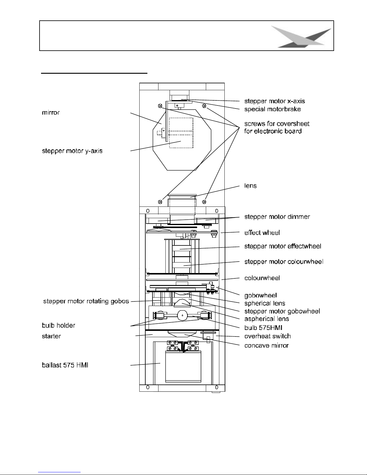
Illustration of VS 4 1200HMI...................................................................................................................24
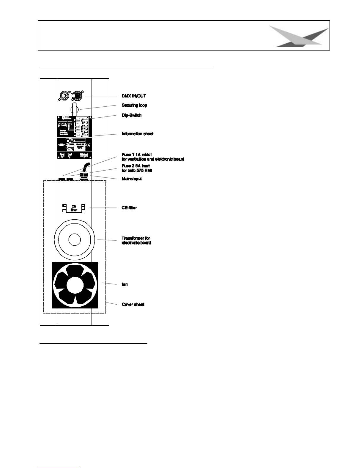
Back view and position of operating sections .....................................................................................25
Occupation of DMX-sockets..............................................................................................................25
Unpacking of the Varyscan®equipment ...............................................................................................26
Put in/ Exchange of the Bulb ..................................................................................................................26
Mounting of Mirror ...................................................................................................................................26
Starting the Equipment...........................................................................................................................26
Initialisation Mode ...............................................................................................................................27
Test Mode............................................................................................................................................27
Adjustments at DIP -Switch No.2 .......................................................................................................27
2. 6 channel drive mode (Clay Paky - Goldenscan 3 compatible).................................................27
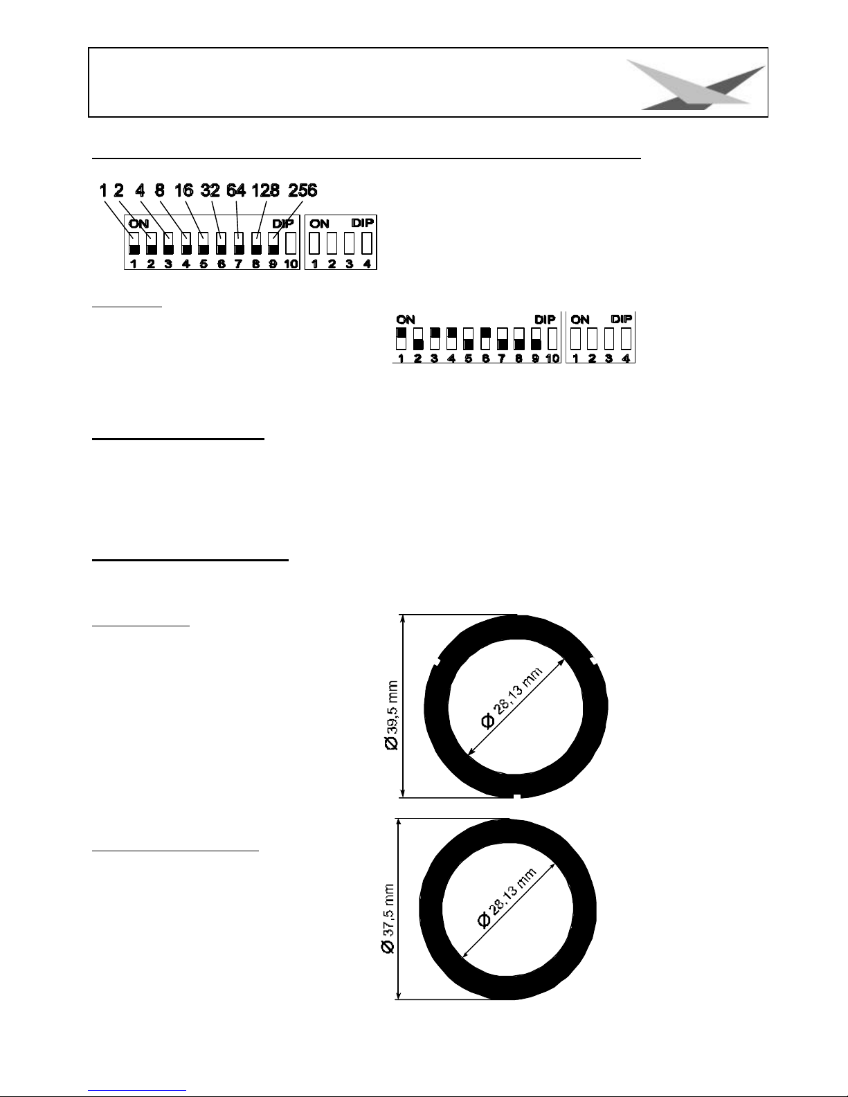
Definition of DIP -switch positions for defined DMX-addresses ........................................................29
Changing of gobos .............................................................................................................................29
GOBO measurements........................................................................................................................29
B Service instructions .............................................................................................................................30
Repair of defects.................................................................................................................................30
Adjustment of mirror stop ...................................................................................................................30
Adjustment of the motor brake...........................................................................................................30
Regular Maintenance Performances ................................................................................................30
1. Cleaning of all Optical Parts ......................................................................................................31
2. Cleaning of Ventilation...............................................................................................................31
3 Oiling of Rotating Gobos.............................................................................................................31
General Informations on DMX512 Record...........................................................................................31
Occupation of Channels for Varyscan®4 Compact Plus 575 HMI.....................................................32
JB lighting 8 channels .........................................................................................................................32
6 channels (Clay Paky Goldenscan 3 compatible)..........................................................................33
JB lighting 6 channel...........................................................................................................................34
Occupation DMX-In / DMX-Out .............................................................................................................36
Technical data .........................................................................................................................................36
Change of Eprom/ Software Update ....................................................................................................36
Plan of current circuits for Varyscan®4 Compact Plus 575 HMI........................................................37
Occupation of connectors and Jumper.................................................................................................38
List of parts for electronic board of Varyscan®4 Compact Plus 575 HMI ........................................38
Plan of electronic parts for electronic board of VS 4 Compact Plus 575 HMI .................................40

24
VARYSCAN 4 COMPACT PLUS 575 HMI
Illustration of VS 4 1200HMI

25
VARYSCAN 4 COMPACT PLUS 575 HMI
Back view and position of operating sections
Occupation of DMX-sockets
DMX-in DMX-out
Pin No. signal Colour of wire Pin No. Signal Colour of wire
1 Ground black 1 Ground black
2 DMX - white 2 DMX - white
3 DMX + red 3 DMX + red
4 free 4 not connected
5 free green/black 5 not connected

26
VARYSCAN 4 COMPACT PLUS 575 HMI
Unpacking of the Varyscan®equipment
Varyscan®4 Compact Plus 575 HMI
operating instructions
Check, if the delivery contains all parts.
Should you notice a damage through transportation, please inform immediately the carriers respectively your dealer.
Also in case of noticing missing parts.
Put in/ Exchange of the Bulb
Warning: Before opening pull out mains plug!
Loosen the screws at the lid of your Varyscan®with a suitable screw-driver and lift the lid (label Varyscan®4 Compact
Plus 575 HMI). You can see the bulb holder in the back third of your Varyscan®
(see sketch page 4). Now detach nuts No.1 and No.2 and remove the bulb from
it's holder. Put the new HMI bulb into the holder and tighten nuts No.1 and No.2
by hand. The point on the glass of the bulb should on no account point to the
concave mirror, respectively to the lenses (sketch page 4), it should point to
the base sheet or to the lid. Take care that the bulb is tightened in the holder.
Warning:Never touch the glass of bulb of the 575 HMI bulb itself !
An adjustment of the bulb is not necessary.
Mounting of Mirror
Take the mirror with the metalsheet, put it on the y-motor and close the screws.
Starting the Equipment
1. Hang up of Varyscan®
To scoop the optimal functioning of your Varyscan®, you should hang up the spots as high as possible.
2. Adjustment of Varyscan®
All spots should hang in the same angle, i.e. the imagined angle between perpendicular and Varyscan®should be the
same among all Varyscans*.
3. Cabling of Varyscan®
Power supply:
A specialist should attach a plug to the open end of the connecting cable, or have the cable connected to 230 Volt 50
Hertz.
DMX-cabling:
Connect the output of your DMX-controller with the first Varyscan®(controller DMX-out; Varyscan®DMX-in) with the
aid of a 5pole XLR-cabel. Now establish the connection between the Varyscans®with the aid of further 5pole XLR-
cables. Make sure that in DMX-out of the last Varyscan®there is a resistor (XLR-plug with a resistance of 100 Ohm
between pin 2 and pin 3) plugged into.
4. Adjustment at DIP-switches
At DIP-switch No.1 and No.2 you have the following possibilities of adjustment:

27
VARYSCAN 4 COMPACT PLUS 575 HMI
?initialisation mode
?test mode
?infinitely variable colour changing
?optional channels of Varyscan®
?reset on DMX
?DMX-address
Initialisation Mode
This mode serves for adjustment and basic initialisation of the Varyscan®(carrying-
out by producer).
Test Mode
To see the variety of functions of your Varyscan®easily, start the test mode by
turning switch 3 off and switch 2 on at DIP-switch No.2. Now plug in your scanner
and you will largely see it's functions.
Adjustments at DIP-Switch No.2
Before adjusting DMX-addresses, you have to choose a certain drive mode and then make the right choice of
addresses.
At DIP-switch No.2 you find 4 switches for choosing the following functions.
Infinitely Variable Colour Changing:
DIP-switch No.2 switch 1
i.e. the moment this function is turned on, every DMX-factor between 0 and 128
corresponds to an adjustment of the colour wheel. You can produce not only half
colours but 1/3- 2/3 colours or 1/4- 3/4 colours etc. To choose this function, turn
switch 1 at DIP-switch No.2 on.
Is switch 1 on position off, you get only full colours, respectively half colours.
Optional Drive Modes:
DIP-switch No.2 switch 2 and 3
You have 3 DMX-channel formats to your disposal, which are explained precisely in the following text.
1. JB lighting 8 channel drive mode
channel 1 x-axis
channel 2 y-axis
channel 3 gobo
channel 4 colour
channel 5 shutter/dimmer
channel 6 iris
channel 7 rotating gobos; positioning and rotation
channel 8 effect wheel
DIP-switch position: DIP-switch No.2 switch 2 and 3 off
2. 6 channel drive mode (Clay Paky - Goldenscan 3 compatible)
channel 1 iris and gobo rotation
channel 2 colour
channel 3 gobo and effect wheel

28
VARYSCAN 4 COMPACT PLUS 575 HMI
channel 4 dimmer/shutter
channel 5 x-axis
channel 6 y-axis
DIP-switch position: DIP-switch No.2 switch 2 off, switch 3 on
3. JB-lighting 6 channel drive mode
channel 1 x-motor
channel 2 y-motor
channel 3 gobo
channel 4 colour
channel 5 dimmer/shutter
channel 6 iris/gobo rotation
DIP-switch position: DIP-switch No.2 switch 2 and 3 on
Reset on DMX:
DIP-switch No.2 switch 4
If you would like to reset your Varyscan®from your DMX-desk, turn switch 4 on at DIP-switch No.2. Now you have
the possibility to reset your Varyscan®, if you transmit DMX-factor 255 via gobo channel.
If switch 4 at DIP-switch No.2 is turned off, reset on
DMX is not possible.
Adjustment of DMX-Addresses:DIP-switch No.1 switch 1-9
Depending on the optional drive mode, you have to adjust DMX-addresses as follows. The addressing works by a
binary numeral system and in 6 channel drive mode it has to follow in six steps.
In 8 channel drive mode addresses have to be adjusted in 8 steps.

29
VARYSCAN 4 COMPACT PLUS 575 HMI
Definition of DIP-switch positions for defined DMX-addresses
Every single DIP-switch responds to the above designated
figures. If you would like to adjust a defined DMX-address, you
have to add up the single figures to get it.
For example: DMX-address "45"
32 + 8 + 4 + 1 = 45
SW6 SW4 SW3 SW1
on on on on
All remaining DIP-switches SW9 SW8 SW7 SW5 SW2 stay in position "OFF".
Changing of gobos
Open the lid with the label Varyscan®4 Compact Plus 575 HMI, by screwing off the four screws. After opening you
should unscrew the silver screws on the side of the Varyscan®to put out the slides. Now you are able to press the
gobos at the gobo wheel out of their holder and then put in other gobos. Take care that the gobo engages exactly
with it's slits in the holder. If the gobo is put in correctly, it moves easily inside the holder. Now you can close the lid.
GOBO measurements
With your Varyscan®, you have the chance of using two different gobo sizes.
1. Gobos JB-size
Outside diameter: 39,5 mm
Use diameter: 28,13 mm
The three slits are placed in an angle of
120° and they are 3,2mm long and 1mm
deep
2. Standard size (E-size)
Outside diameter: 37,5 mm
Use diameter: 28,13 mm

30
VARYSCAN 4 COMPACT PLUS 575 HMI
B Service instructions
Repair of defects
Defect Reparation
The appliance does not work at all (you can not
see any light inside your Varyscan®)
Exchange 8 Ampere fuse of the appliance
The bulb of the appliance does not shine, but
electronics are working, i.e. motors are working,
fan is working
1. The bulb is defect, you have to change it
2. The temperature switch of the appliance is
released. Plug out your Varyscan®and after
approximately 15 minutes plug it in again. Check
now, if the ventilator is working and if it is clean. If
the ventilator is defect, have it exchanged by a
specialist or the producer. If the scanner turns off
again and again, please contact your dealer.
DMX-input does not work Control DIP-switch position
Adjustment of mirror stop
To adjust the mirror of your Varyscan®1200 HMI, proceed as
follows:
Adjust the initialisation mode at DIP- switch No.1 (DIP-switch
position see page 7) and start your Varyscan®. Now wait until
the initialisation of the scan is ran through and all motors
stopped. Then loosen screw No.1 Now turn the holder for the y-
motor towards the stop up to a distance of 0,5 mm. Tighten
screw No.1 now. During tightening the screw pay attention to
the correct adjustment of the motor brake (see sketch below).
Loosen screw No.2 and turn the y-motor towards the holder for
the y-motor and adjust hereby a distance of 0,5 mm between
the stop and the holder for the y-motor.
Adjustment of the motor brake
The motor brake is similar at each of the stepping-motor of the scan. There are three special parts (part no. 2,3 and
4) which must be installed in the following succession:
Part no. 1. motor
Part no. 2. Tellerfedern
Part no. 3. Stahllaserteil
Part no. 4. Kunststoffscheibe
Part no. 5. zu montierendes Teil
Part no. 5 has to be pushed on the axis of the stepping-motor until the parts no.
2 can not be compressed anymore. After remove the part no. 5 about 0,5 mm.
After turn the fastening screws. The "motor-brake" is now optimum adjusted .
Regular Maintenance Performances
Warning: Before opening the appliance pull out mains plug!

31
VARYSCAN 4 COMPACT PLUS 575 HMI
Open the casing by turning out the screws at the top of the Varyscan®.
To be able to take out the slide-in modules of your Varyscan®, you have to screw off two screws of silver at the side-
piece, up to the mark of the slide-in modules. Now you are able to take out the slide-in modules (sketch page 4).
Direction: Do not forget to lock in the slide-in modules after having completed
your maintenance performances, by screwing in the screws of silver carefully!
1. Cleaning of all Optical Parts
You should clean the optical parts of your Varyscan®periodically to restore maximum brightness of the scan. After
having opened the casing as explained above, take out the effect / colour wheel slide-in (see sketch page 4) and put
it on an underlay before you. Take a fuzz-free rag and a detergent for windows and clean the effect / colour filters.
Subsequently clean both lenses (sketch page 4). In order to clean the lens easily, loosen the screw which fixes the
lens and remove the lens. Now it is easy to clean from the outside and the inside. Put in the lens and the effect
colour wheel slide-in. Do not forget to tighten the screw which fixes the lens and the screws which fixes the slide-in’s
2. Cleaning of Ventilation
You should check the function of ventilators regularly. Above all take care that ventilation inlets and the interior of the
Varyscan®are free from fuzzes and other dust. Open both lids of your Varyscan®, by screwing off the screws from the
lids. Now clean your Varyscan®carefully with a vacuum cleaner. Screw down the lid now. Take care that you use the
sheet metal screws for closing the smaller lid.
Attention: Take care that you do not twist or damage any parts while cleaning your scanner!
3 Oiling of Rotating Gobos
Procure a syringe with a thin needle, customary in trade (grind off the tip, so it will be blunt - no risk of injury!!), and fill
it with our special oil. On no account use another kind of oil, because our oil is a special mixture. Now syringe
the oil between the brass gear wheels and the brass plate and turn the rotating gobos by hand.
Attention: Do not use too much oil!
General Informations on DMX512 Record
DMX 512 record is devided in 512 addresses. You have 512 addresses to your disposal. To be able to connect
different appliances with a DMX-controller, it is necessary to determine the number of DMX-channels for every
appliance. The occupation of channels of a scanner could be like that for example:
channel 1 x-movement
channel 2 y-movement
channel 3 gobo/effect wheel
channel 4 colour
channel 5 shutter/dimmer
channel 6 iris/gobo positioning/gobo rotation
In order that not every connected DMX-appliance performs same functions, the appliances are addressed in series;
i.e. for the first appliance the first 6 addresses are used (be right for an appliance with six channels), for the second

32
VARYSCAN 4 COMPACT PLUS 575 HMI
one (appliance with six channels) the next 6 addresses of all the DMX-addresses are used (see for example
Varyscan®page 10).
Occupation of Channels for Varyscan®4 Compact Plus 575 HMI
JB lighting 8 channels
Channel 1 X-movement
Channel 2 Y-movment
Channel 3 gobo
Channel 4 color
Channel 5 shutter / dimmer
Channel 6 iris
Channel 7 rotating gobos (positioning and rotating)
Channel 8 effect wheel
channel 1 Pan movement 170°
channel 2 Tilt movement 90°
channel 3 gobo
gobo 0 (Beam) DMX 000 - 031
gobo 1 DMX 032 - 063
gobo 2 DMX 064 - 095
gobo 3 DMX 096 - 127
gobo 4 DMX 128 - 159
gobo 5 DMX 160 - 255
if at DIP-switch No.2 switch 4 is "ON"
gobo 5 DMX 160 - 254
Reset DMX 255
channel 4 colour
colour 0 (white) DMX 000 - 007
colour 1 DMX 008 - 015
colour 2 (red) DMX 016 - 023
colour 3 DMX 024 - 031
colour 4 (yellow) DMX 032 - 039
colour 5 DMX 040 - 047
colour 6 (pink) DMX 048 - 055
colour 7 DMX 056 - 063
colour 8 (green) DMX 064 - 071
colour 9 DMX 072 - 079
colour 10 (orange) DMX 080 - 087
colour 11 DMX 088 - 095
colour 12 (blue) DMX 096 - 103
colour 13 DMX 104 - 111
colour 14 (dark-green) DMX 112 - 119
colour 15 DMX 120 - 127
colour wheel rotation speed 1 (slow) DMX 128 -
colour wheel rotation speed 7 (fast) DMX 255
channel 5 dimmer / shutter
dimmer shutter closed --> blackout (BO) DMX 000
Dimmer 0 – 99% DMX 020 - 127
dimmer open DMX 128 - 137
dimmer shutter immediatelly DMX 138 - 139
shutter sequence 1,00 flashes/sec DMX 140 -
shutter sequence 11,00 flashes/sec DMX 243

33
VARYSCAN 4 COMPACT PLUS 575 HMI
shutter open DMX 244 - 255
channel 6 iris
iris (linear) DMX 000 -
255
channnel 7 rotating gobos (positioning and rotation)
0° DMX 000
180° DMX 063
360° DMX 126
540° DMX 191
rotation left (fast) DMX 192
rotation left (slow) DMX 222
rotation stop DMX 223 - 224
rotation right (slow) DMX 225
rotation right (fast) DMX 255
channel 8 effect wheel
open DMX 000 - 031
artificial light filter DMX 032 - 063
daylight filter DMX 064 - 095
prism DMX 096 - 111
movable prism (slow) DMX 112 -
movable prism (fast) DMX 127
floodfilter DMX 128 - 159
infinitely variable from flood to open DMX 160 - 255
6 channels (Clay Paky Goldenscan 3 compatible)
channel 1 iris and gobo rotation
channel 2 colour
channel 3 gobo and effect wheel
channel 4 dimmer / shutter
channel 5 pan movement
channel 6 tilt movement
channel 1 iris and gobo rotation
iris closed / gobo first position DMX 000
iris open / gobo first position DMX - 064
second gobo position DMX 065
third gobo position DMX 066
locked into position 180° DMX 106
locked into position 360° DMX 148
locked into position 540° DMX 191
rotation left fast DMX 192
rotation left slow DMX 222
rotation stop DMX 223 - 224
rotation right slow DMX 225
rotation right highest speed DMX 255
channel 2 colour
colour 0 (white) DMX 000 - 007
colour 1 DMX 008 - 015
colour 2 DMX 016 - 023
colour 3 DMX 024 - 031
colour 4 DMX 032 - 039
colour 5 DMX 040 - 047
colour 6 DMX 048 - 055
colour 7 DMX 056 - 063

34
VARYSCAN 4 COMPACT PLUS 575 HMI
colour 8 DMX 064 - 071
colour 9 DMX 072 - 079
colour 10 DMX 080 - 087
colour 11 DMX 088 - 095
colour 12 DMX 096 - 103
colour 13 DMX 104 - 111
colour 14 DMX 112 - 119
colour 15 DMX 120 - 127
colour wheel rotation speed (slow) DMX 128 -
colour wheel rotation speed (fast) DMX 255
channel 3 gobo and effect wheel
white DMX 000 - 008
artificial light filter DMX 009 - 017
daylight filter DMX 018 - 026
prism DMX 027 - 035
floodfilter DMX 036 - 044
gobo 1 white DMX 045 - 053
gobo 1 artificial light filter DMX 054 - 062
gobo 1 daylight filter DMX 063 - 071
gobo 1 prism DMX 072 - 080
gobo 2 white DMX 081 - 089
gobo 2 artificial light filter DMX 090 - 098
gobo 2 daylight filter DMX 099 - 107
gobo 2 prism DMX 108 - 116
gobo 3 white DMX 117 - 125
gobo 3 artificial light filter DMX 126 - 134
gobo 3 daylight filter DMX 135 - 143
gobo 3 prism DMX 144 - 152
gobo 4 white DMX 153 - 161
gobo 4 artificial light filter DMX 162 - 170
gobo 4 daylight filter DMX 171 - 179
gobo 4 prism DMX 180 - 188
gobo 5 white DMX 189 - 197
gobo 5 artificial light filter DMX 198 - 206
gobo 5 daylight filter DMX 207 - 215
gobo 5 prism DMX 216 - 255
if at DIP-switch No. 2 switch is "ON"
GOBO 5 prism DMX 216 - 254
Reset DMX 255
channel 4 dimmer / shutter
dimmer shutter closed --> blackout (BO) DMX 000
dimmer 0 – 99% DMX 020 - 127
dimmer open DMX 128 - 137
dimmer shutter immediatelly closed DMX 138 - 139
shutter sequence 1,00 flashes/sec DMX 140 -
shutter sequence 11,00 flashes/sec DMX 243
shutter open DMX 244 - 255
channel 5 Pan movement 170°
channel 6 Tilt movement 90°
JB lighting 6 channel
channel 1 X-axis

35
VARYSCAN 4 COMPACT PLUS 575 HMI
channel 2 Y-axis
channel 3 gobo and effect wheel
channel 4 colour
channel 5 simmer shutter
channel 6 iris and goborotation
channel 1 Pan movement 170°
channel 2 Tilt movement 90°
channel 3 gobo and effektwheel
white DMX 000 - 008
artificial light filter DMX 009 - 017
daylight filter DMX 018 - 026
prism DMX 027 - 035
floodfilter DMX 036 - 044
gobo 1 white DMX 045 - 053
gobo 1 artificial light filter DMX 054 - 062
gobo 1 daylight filter DMX 063 - 071
gobo 1 prism DMX 072 - 080
gobo 2 white DMX 081 - 089
gobo 2 artificial light filter DMX 090 - 098
gobo 2 daylight filter DMX 099 - 107
gobo 2 prism DMX 108 - 116
gobo 3 white DMX 117 - 125
gobo 3 artificial light filter DMX 126 - 134
gobo 3 daylight filter DMX 135 - 143
gobo 3 prism DMX 144 - 152
gobo 4 white DMX 153 - 161
gobo 4 artificial light filter DMX 162 - 170
gobo 4 daylight filter DMX 171 - 179
gobo 4 prism DMX 180 - 188
gobo 5 white DMX 189 - 197
gobo 5 artificial light filter DMX 198 - 206
gobo 5 daylight filter DMX 207 - 215
gobo 5 prism DMX 216 - 255
if at DIP-switch No. 2 switch is "ON"
GOBO 5 prism DMX 216 - 254
Reset DMX 255
channel 4 colour
colour 0 (white) DMX 000 - 007
colour 1 DMX 008 - 015
colour 2 (red) DMX 016 - 023
colour 3 DMX 024 - 031
colour 4 (yellow) DMX 032 - 039
colour 5 DMX 040 - 047
colour 6 (pink) DMX 048 - 055
colour 7 DMX 056 - 063
colour 8 (green) DMX 064 - 071
colour 9 DMX 072 - 079
colour 10 (orange) DMX 080 - 087
colour 11 DMX 088 - 095
colour 12 (blue) DMX 096 - 103
colour 13 DMX 104 - 111
colour 14 (dark-green) DMX 112 - 119
colour 15 DMX 120 - 127
colour wheel rotation speed (slow) DMX 128 -

36
VARYSCAN 4 COMPACT PLUS 575 HMI
colour wheel rotation speed (fast) DMX 255
channel 5 dimmer / shutter
dimmer shutter closed --> blackout (BO) DMX 000
dimmer DMX 019 - 127
dimmer open DMX 128 - 137
dimmer shutter immediatelly DMX 138 - 139
shutter sequence 1,00 flashes/sec DMX 140 -
shutter sequence 11,00 flashes/sec DMX 243
shutter open DMX 244 - 255
channel 6 iris and gobo rotation
iris closed / gobo first position DMX 000
iris open / gobo first position DMX - 064
second gobo position DMX 065
third gobo position DMX 066
locked into position 180° DMX 106
locked into position 360° DMX 148
locked into position 540° DMX 191
rotation left highest speed DMX 192
rotation left lowest speed DMX 222
rotation stop DMX 223 - 224
rotation right lowest speed DMX 225
rotation right highest speed DMX 255
Occupation DMX-In / DMX-Out
Position of sockets see page 5
DMX-IN DMX-OUT
Pin1: ground black Pin1: ground black
Pin2: DMX- beige Pin2: DMX- beige
Pin3: DMX+ red Pin3: DMX+ red
Pin4: frei Pin4: frei
Pin5: + 5V green Pin5: frei
Technical data
Measurements: hight 65 cm
width 27 cm
depth 29 cm
Weight: 19 kg
Power consumption: 1725 W
Mains Voltage: 230V 50Hz 7A
Bulb : Osram 575 HMI
Fuse: 8 ampere inert
Change of Eprom/ Software Update
To change the Eprom proceed as follows:
Remove the cover sheet for the electronic board below the mirror by taking out the 4 screws (see sketch page 4). By
comparing the electronic board with the plan of electronic parts you can see the Eprom at the right side (IC U2).
Carefully lever the used Eprom from the holder and exchange it for a new one.

37
VARYSCAN 4 COMPACT PLUS 575 HMI
Direction: Pay attention to the polarity of the Eprom!
(The inlet of the Eprom has to point to the same direction as the inlet of the IC-holder.)
Close the lid and fix it with screws. Plug in your Varyscan®and please test all functions.
Plan of current circuits for Varyscan®4 Compact Plus 575 HMI

38
VARYSCAN 4 COMPACT PLUS 575 HMI
Occupation of connectors and Jumper
Pin colour Pin colour Pin colour Pin colour connector
x-motor 1 orange 2 blue 3 red 4 yellow JP2
y-motor 1 white 2 blue 3 red 4 yellow JP3
effect wheel 1 orange 2 blue 3 yellow 4 red P2
colour wheel 5 orange 6 blue 7 yellow 8 red P2
shutter/dim.1 1 orange 2 blue 3 red 4 yellow JP4
shutter/dim.2 1 orange 2 blue 3 red 4 yellow JP5
gobo wheel 5 orange 6 blue 7 yellow 8 red P1
gobo rotation 1 orange 2 blue 3 yellow 4 red P1
Iris 13 white 14 red 15 black free free P1
DMX In/Out 1 white 2 red 3 black 4 gr/bl JP1
List of parts for electronic board of Varyscan®4 Compact Plus 575 HMI
R1 10M 0,6W R41 1R 1W
R2 22K 0,6W R42 36R 1W
R3 9*10K Sip 0,25W R43 36R 1W
R4 9*10K Sip 0,25W R44 1R 1W
R5 10K 0,6W R45 1R 1W
R6 10K 0,6W R46 768R 0,6W
R7 10K 0,6W R47 249R 0,6W
R8 470R 0,6W
R9 2k2 0,6W U1 M68HC11F1FN
R10 15 k 0,6W U2 EPROM27C256
R11 1k 0,6W U3 AM 26LS32
R12 1k 0,6W U4 74HC245
R13 15k 0,6W U5 74HC138
R14 1k 0,6W U6 PBL3771
R15 15k 0,6W U7 PBM3960
R16 0R68 1W U8 PBL3771
R17 0R68 1W U9 PBM3960
R18 1R 1W U10 PBL3771
R19 1R 1W U11 PBM3960
R20 1k 0,6W U12 TCA3727
R21 1R 1W U15 TCA3727
R22 1k 0,6W U18 TCA3727
R23 1R 1W U20 TCA3727
R24 1k 0,6W
R25 1R 1W S1 SW DIP-10
R26 1R 1W S2 SW DIP-4
R27 30R 1W
R28 60R 0,6W
R29 240R 0,6W
R30 120R 0,6W

39
VARYSCAN 4 COMPACT PLUS 575 HMI
R31 30R 1W
R32 60R 0,6W
R33 240R 0,6W
R34 120R 0,6W
R35 4R 1W
R36 1R 1W
R37 1R 1W
R38 36R 1W
R39 36R 1W
R40 1R 1W
C1 18pF C41 220nF
C2 18pF C42 2,2nF
C3 4,7uF/35V C43 100nF
C4 100nF C44 470uF/35V
C5 100nF C45 2,2nF
C6 22uF/35V C46 47u/35V
C7 100nF C47 220nF
C8 100nF C48 47u/35V
C9 100nF C49 220nF
C10 820pF C50 4700uF/35V
C11 820pF D1 LM336
C12 47uF/35V D2 Bridge
C13 220nF F1 Fuse
C14 220nF JP1 Header 4
C15 47uF/35V JP2 Header 4
C16 220nF JP3 Header 4
C17 220nF JP4 Header 4
C18 100nF JP5 Header 4
C19 3,3nF JP6 Header 2
C20 220nF P1 Connector DB15
C21 47uF/35V P2 Connector DB15
C22 220nF Q1 BC337B
C23 47uF/35V Q2 BC337B
C24 820pF Q3 BC337B
C25 820pF Q4 BC337B
C26 3,3nF Q5 BC337B
C27 47uF/35V Q6 BC337B
C28 220nF Q7 BC337B
C29 220nF Q8 BC337B
C30 220nF Q9 BC337B
C31 47uF/35V Q10 BC337B
C32 820pF Q11 BC337B
C33 820pF Q12 BC337B
C34 3,3nF Q13 BC337B
C35 220nF Y1 Quarz 16MHz
C36 220nF
C37 2,2nF
C38 47uF/35V
C39 220nF
C40 47uF/35V

40
VARYSCAN 4 COMPACT PLUS 575 HMI
Plan of electronic parts for electronic board of VS 4 Compact Plus 575
HMI
Table of contents
Other JB-Lighting Lighting Equipment manuals

JB-Lighting
JB-Lighting Varyscan 4 1200HMI User manual

JB-Lighting
JB-Lighting Varyscan 3 Special 250MSD User manual

JB-Lighting
JB-Lighting P18 MK2 Wash HP User manual

JB-Lighting
JB-Lighting VARYSCAN 7 User manual

JB-Lighting
JB-Lighting P18 User manual

JB-Lighting
JB-Lighting SPARX 12 Firmware update

JB-Lighting
JB-Lighting Upgrade-Dongle User manual