JB Systems AMP 150.4 User manual


ENGLISH USER MANUAL
JB SYSTEMS®1/34 AMP 150.4
OPERATION MANUAL
Thank you for buying this JB Systems®product. To take full advantage of all possibilities, please read these
operating instructions very carefully.
FEATURES
This unit is radio-interference suppressed. This appliance meets the requirements of the current European
and national guidelines. Conformity has been established and the relevant statements and documents have
been deposited by the manufacturer.
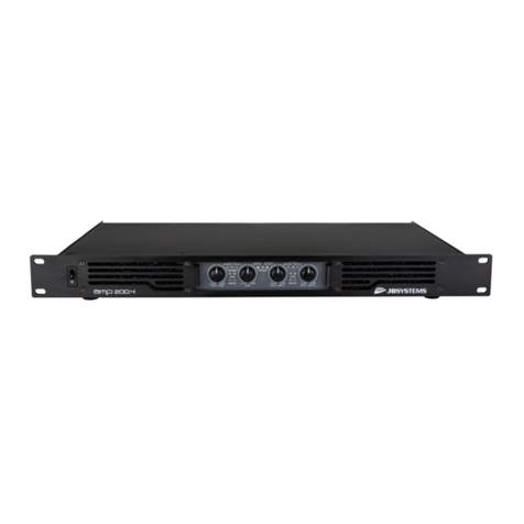
Professional 4-channel power amplifier in an extremely compact 19" 1U-housing (H: 44mm)
The high efficient class-D design guarantees high power and very low heat dissipation.
Perfect for install applications (pubs, shops, hotels, restaurants, … )
The unit houses 2 separate class-D amplifiers that can be configured independently to obtain the following
combinations:
Both amps in stereo mode: 4x 150Wrms @ 4Ω (4x 80Wrms @ 8Ω)
Both amps in Bridge mode: 2x 300Wrms @ 8Ω
1amp in stereo + one amp in bridge: 2x 150Wrms @ 4Ω + 1x 300Wrms @ 8Ω
Completely silent operation: NO cooling fans!
Peak limiter prevents signal distortion
DC fault + high temperature + overload + short circuit protections
Balanced Combo (XLR + jack) inputs.
Speakon® + bind-post wire terminal outputs
BEFORE USE
Before you start using this unit, please check if there’s no transportation damage. Should there be any, do
not use the device and consult your dealer first.
Important: This device left our factory in perfect condition and well packaged. It is absolutely necessary
for the user to strictly follow the safety instructions and warnings in this user manual. Any damage caused
by mishandling is not subject to warranty. The dealer will not accept responsibility for any resulting defects
or problems caused by disregarding this user manual.
Keep this booklet in a safe place for future consultation. If you sell the fixture, be sure to add this user
manual.
To protect the environment, please try to recycle the packing material as much as possible.
Check the contents:
Check that the carton contains the following items:
Power amplifier
Operating instructions
Mains power cable.
SAFETY INSTRUCTIONS:
CAUTION
CAUTION: To reduce the risk of electric shock, do not
remove the top cover. No user-serviceable parts inside.
Refer servicing to qualified service personnel only.
The lightning flash with arrowhead symbol within the equilateral triangle is intended to alert the
use or the presence of un-insulated “dangerous voltage” within the product’s enclosure that may
be of sufficient magnitude to constitute a risk of electric shock.
The exclamation point within the equilateral triangle is intended to alert the user to the presence of
important operation and maintenance (servicing) instructions in the literature accompanying this
appliance.

ENGLISH USER MANUAL
JB SYSTEMS®2/34 AMP 150.4
To prevent fire or shock hazard, do not expose this appliance to rain or moisture.
To avoid condensation to be formed inside, allow the unit to adapt to the surrounding temperatures when
bringing it into a warm room after transport. Condense sometimes prevents the unit from working at full
performance or may even cause damages.
This unit is for indoor use only.
Don’t place metal objects or spill liquid inside the unit. No objects filled with liquids, such as vases, shall be
placed on this appliance. Electric shock or malfunction may result. If a foreign object enters the unit,
immediately disconnect the mains power.
No naked flame sources, such as lighted candles, should be placed on the appliance.
Don’t cover any ventilation openings as this may result in overheating.
Prevent use in dusty environments and clean the unit regularly.
Keep the unit away from children.
Inexperienced persons should not operate this device.
Maximum save ambient temperature is 40°C. Don’t use this unit at higher ambient temperatures.
Minimum distances around the apparatus for sufficient ventilation is 3cm.
Always unplug the unit when it is not used for a longer time or before you start servicing.
The electrical installation should be carried out by qualified personal only, according to the regulations for
electrical and mechanical safety in your country.
Check that the available voltage is not higher than the one stated on the rear panel of the unit.
The socket inlet shall remain operable for disconnection from the mains.
The power cord should always be in perfect condition. Switch the unit immediately off when the power cord
is squashed or damaged. It must be replaced by the manufacturer, its service agent or similarly qualified
persons in order to avoid a hazard.
Never let the power-cord come into contact with other cables!
When the power switch is in OFF position, this unit is not completely disconnected from the mains!
This appliance must be earthed to in order comply with safety regulations.
In order to prevent electric shock, do not open the cover. Apart from the mains fuse there are no user
serviceable parts inside.
Never repair a fuse or bypass the fuse holder. Always replace a damaged fuse with a fuse of the same
type and electrical specifications!
In the event of serious operating problems, stop using the appliance and contact your dealer immediately.
Please use the original packing when the device is to be transported.
Due to safety reasons it is prohibited to make unauthorized modifications to the unit.
INSTALLATION GUIDELINES:
Install the unit in a well-ventilated location where it will not be exposed to high temperatures or humidity.
Placing and using the unit for long periods near heat-generating sources such as amplifiers, spotlights, etc.
will affect its performance and may even damage the unit.
The unit can be mounted in 19-inch racks. Attach the unit using the 4 screw holes on the front panel. Be
sure to use screws of the appropriate size. (screws not provided) Take care to minimize shocks and
vibrations during transport.
When installed in a booth or flight case, please make sure to have good ventilation to improve heat
evacuation of the unit.
To avoid condensation to be formed inside, allow the unit to adapt to the surrounding temperatures when
bringing it into a warm room after transport. Condense sometimes prevents the unit from working at full
performance.
CLEANING THE APPLIANCE:
Clean by wiping with a cloth slightly dipped with water. Avoid getting water inside the unit.
Do not use volatile liquids such as benzene or thinner which will damage the unit.
Clean the ventilation holes regularly with a vacuum cleaner. This increases the cooling capacity of the
amplifier fans and helps preventing temperature overheat.
This symbol means: indoor use only
This symbol means: Read instructions

ENGLISH USER MANUAL
JB SYSTEMS®3/34 AMP 150.4
CONNECTIONS
Be sure to turn off the unit before you make changes to the wiring. Use good quality signal cables to ensure
excellent audio quality. For example use JB cables with order codes: 7-0061 (XLR/XLR L=1m) or 7-0063
(XLR/XLR L=5m). For the speakers we suggest using the Speakon®compatible outputs. Suitable cables are
for example JB order codes: 2-0505 (L=5m) or 2-0510 (L=10m).
FUNCTIONS (FRONT)
This amplifier has 2 totally independent stereo amplifiers inside: amplifier 1 serves channels 1+2, amplifier 2
serves channels 3+4. Both amplifiers can be used in a different working mode (stereo, parallel or bridge)
which gives you more flexibility. Refer to the chapter “HOW TO USE” for more information.
1. POWER LED: This white led is on when you turn the amplifier on using switch(2).
2. MAINS SWITCH: Used to turn the amplifier on and off. A few seconds after switching on the amplifier it
is ready for operation.
3. GAIN CONTROL CH1:used to control the input sensitivity of amplifier channel1. Use this input when
amplifier 1 is set to parallel or bridge mode.
4. GAIN CONTROL CH2:used to control the input sensitivity of amplifier channel2. This input is NOT used
when amplifier 1 is set to parallel or bridge mode.
5. GAIN CONTROL CH3:used to control the input sensitivity of amplifier channel3. Use this input when
amplifier 2 is set to parallel or bridge mode.
6. GAIN CONTROL CH4:used to control the input sensitivity of amplifier channel4. This input is NOT used
when amplifier 2 is set to parallel or bridge mode.
7. SIGNAL LEDS: these LEDs indicate that a music signal is present at the inputs.
8. CLIP LEDS: Lit just before the maximum, distortion free, output level of the amplifier. They indicate that
the internal limiter starts working. The clip LEDs may turn on shortly from time to time but they may
certainly not turn on for longer periods. In this case you have to turn the output level down!
9. AUDIO PROTECT LED: is on when the speakers are disconnected from the amplifier. This occurs in the
following situations:
During the first seconds after switching on the amplifier.
When the temperature of the power stage becomes too high.
In case of a technical defect: DC protection, overload, short circuit, …
While switching the amplifier off, the “protect led” turns on for a short time.
FUNCTIONS (rear)
10. OPERATION MODE switch: Used to set the operation mode of amplifier 1 (CH1+2):
STEREO: The most common operation mode, CH1+2 are routed to their corresponding outputs.
PARALLEL: only the mono signal on input channel1 (11) is used to drive both outputs CH1+2.
BRIDGE: used when you need more power. Only the mono signal on input channel1 (11) is used
to drive the combined “bridged” output. Only speakers with impedance >8ohm are allowed.
11. XLR input CH1:you can connect a balanced or unbalanced signal, both XLR and ¼” jacks can be used.
12. XLR input CH2:you can connect a balanced or unbalanced signal, both XLR and ¼” jacks can be used.
Only used while amplifier 1 works in stereo mode (10).
13. BINDING POST output CH1: use this output when the speaker cable has no Speakon connector.

ENGLISH USER MANUAL
JB SYSTEMS®4/34 AMP 150.4
14. BINDING POST output CH2: use this output when the speaker cable has no Speakon®connector.
15. SPEAKON output CH1+2: this Speakon®output is a combined connector for both CH1 and CH2.
CH1: 1+ = positive (red) wire, 1- = negative (black) wire
CH2: 2+ = positive (red) wire, 2- = negative (black) wire
BRIDGE: 1+ = positive (red) wire, 2- = negative (black) wire
16. OPERATION MODE switch: Used to set the operation mode of amplifier 1 (CH3+4):
STEREO: The most common operation mode, CH3+4 are routed to their corresponding outputs.
PARALLEL: only the mono signal on input channel3 (17) is used to drive both outputs CH3+4.
BRIDGE: used when you need more power. Only the mono signal on input channel3 (17) is used
to drive the combined “bridged” output. Only speakers with impedance >8ohm are allowed.
17. XLR input CH3: you can connect a balanced or unbalanced signal, both XLR and ¼” jacks can be used.
18. XLR input CH4: you can connect a balanced or unbalanced signal, both XLR and ¼” jacks can be used.
Only used while amplifier 2 works in stereo mode (16).
19. BINDING POST output CH3: use this output when the speaker cable has no Speakon connector.
20. BINDING POST output CH4: use this output when the speaker cable has no Speakon®connector.
21. SPEAKON output CH3+4: this Speakon®output is a combined connector for both CH3 and CH4.
CH3: 1+ = positive (red) wire, 1- = negative (black) wire
CH4: 2+ = positive (red) wire, 2- = negative (black) wire
BRIDGE: 1+ = positive (red) wire, 2- = negative (black) wire
22. POWER input: Use the supplied power cable to connect the amplifier to the mains. This connector also
holds a 20mm glass fuse. Always replace a blown fuse by another with exactly the same specifications.
(fuse specifications can be found on the rear panel, next to the power input connector)
HOW TO USE
Both amplifiers can be configured separately in 3ways to obtain several configurations.
STEREO OPERATION ON ALL 4 CHANNELS:
Used to drive 2 stereo outputs (4 channels): 4x 80Wrms @ 8Ω ~ 4x 150Wrms @ 4ohm.
Using binding post outputs:
Using SpeakON®outputs:
Connect the stereo audio signals to the inputs 1+2 (11/12) and 3+4 (17/18)
Set the operation mode switches (10/16) to “stereo”
Connect the speakers to the outputs as shown on the drawings.
Set input gain knobs (3/4/5/6) to zero
Make sure there’s a music signal at the input
Turn the amplifier on (2)
Adjust the gain knobs (3/4/5/6) to the desired level

ENGLISH USER MANUAL
JB SYSTEMS®5/34 AMP 150.4
BRIDGE OPERATION:
Used to drive 2 channels: 2x 300Wrms @ 8Ω ~ Attention: loads below 8Ω are NOT allowed.
Using binding post outputs:
Using SpeakON®outputs:
Connect the audio signals to the inputs 1+3 (11/17)
Set the operation mode switches (10/16) to “bridge”
Connect the speakers to the outputs as shown on the drawings.
Set input gain knobs (3/4/5/6) to zero
Make sure there’s a music signal at the left input
Turn the amplifier on (2)
Adjust the gain knobs (3/5) to the desired level, gain knobs (4/6) are not used.
PARALLEL OPERATION:
Used to drive 2 stereo outputs (4 channels) where mono input 1 (11) drives outputs 1+2 (13/14) and mono
input 3 (17) drives outputs 3+4 (19/20) : 4x 80Wrms @ 8Ω ~ 4x 150Wrms @ 4ohm.
Using binding post outputs:
Using SpeakON®outputs:
Connect the audio signals to the inputs 1+3 (11/17)

ENGLISH USER MANUAL
JB SYSTEMS®6/34 AMP 150.4
Set the operation mode switches (10/16) to “parallel”
Connect the speakers to the outputs as shown on the drawings.
Set input gain knobs (3/4/5/6) to zero
Make sure there’s a music signal at the left input
Turn the amplifier on (2)
Adjust the gain knobs (3/5) to the desired level, gain knobs (4/6) are not used.
3WAY OPERATION:
Used to drive 1 stereo output for satellite speakers + 1 mono subwoofer output (total 3 channels).
Note: An optional electronic crossover is needed to split audio in mono sub + stereo satellites!
Satellite speakers: 2x 80Wrms @ 8Ω ~ 4x 150Wrms @ 4ohm.
Subwoofer: 1x 300Wrms @ 8Ω ~ Attention: loads below 8Ω are NOT allowed.
Using binding post outputs:
Using SpeakON®outputs:
Connect the stereo audio signals (from crossover) to the inputs 1+2 (11/12)
Connect the mono audio signal (from crossover) to input 3 (17)
Set the operation mode switch (10) to “stereo”
Set the operation mode switch (16) to “bridge”
Connect the speakers to the outputs as shown on the drawings.
Set input gain knobs (3/4/5/6) to zero
Make sure there’s a music signal at the input
Turn the amplifier on (2)
Adjust the gain knobs (3/4/5) to the desired level (the gain knob for CH4 (6) is not used)
SPECIFICATIONS
Power stereo 4Ω (1kHz, THD:1%) : 150 Wrms / output
Power stereo 8Ω: 80 Wrms / output
Power bridge 8Ω: 300 Wrms / output
Freq. Resp. (+/-1dB): 20 –20000 Hz
Input Sensitivity: +4dBu (1,2Vrms)
S/N ratio: >90 dB
Channel separation: >70 dB
THD@1kHz: <0,1%
Power supply: AC100V~240V / 50Hz~60Hz
Dimensions (mm): 483 x 44 x 330 (19"/1U)
Weight: 5,2 kg
Every information is subject to change without prior notice
You can download the latest version of this user manual on our website: www.jb-systems.eu

FRANÇAIS GUIDE D'UTILISATION
JB SYSTEMS®7/34 AMP 150.4
GUIDE D'UTILISATION
Nous vous remercions d'avoir acheté ce produit JB Systems®. Lisez attentivement les présentes instructions
d'utilisation pour tirer profit de toutes les possibilités du produit.
CARACTÉRISTIQUES
Cet appareil ne produit pas d'interférences radio. Cet appareil répond aux exigences des directives
européennes et nationales en vigueur. La conformité a été établie et les déclarations et documents
correspondants ont été déposés par le fabricant.
Amplificateur de puissance professionnel à 4 voies dans un coffret extrêmement compact 480 mm
(H : 44 mm)
Les circuits électroniques de classe D à haute efficacité garantissent une puissance élevée et une
dissipation de chaleur très faible.
Il est parfait pour les applications fixes (pubs, magasins, hôtels, restaurants, ...)
L'unité abrite 2 blocs d'amplification séparés de classe D qui sont configurables indépendamment pour
obtenir les combinaisons suivantes :
Les deux blocs d'amplification en mode stéréo : 4x 150 W RMS sous 4 Ω (4x 80 W RMS sous 8 Ω)
Les deux blocs d'amplification en mode pont : 2x 300 W RMS sous 8 Ω
1 bloc d'amplification en stéréo+ 1 bloc d'amplification en pont : 2x 150 W RMS sous 4 Ω + 1x 300 W
RMS sous 8 Ω
Fonctionnement complètement silencieux : Aucun ventilateur de refroidissement !
Le limiteur de saturation empêche la distorsion du signal
Protections contre surcharge + surchauffe + court-circuit + courant de fuite continu
Entrées combinées symétriques (XLR + jack).
Sorties par bornier de raccordement de câble + Speakon®
AVANT UTILISATION
Avant d'utiliser cet appareil, vérifiez s'il n'a pas été endommagé durant le transport. En cas de dommages,
n'utilisez pas l'appareil et consultez immédiatement votre revendeur.
Important : Cet appareil est expédié de notre usine en parfait état et bien emballé. Il est absolument
nécessaire que l'utilisateur suive strictement les instructions et les avertissements de sécurité se trouvant
dans ce manuel. Tout dommage dû à une mauvaise manipulation n'est pas garanti. Le revendeur
n'accepte aucune responsabilité pour tous les défauts et problèmes dus au non-respect de ce manuel.
Conservez ce manuel dans un endroit sûr pour toute consultation future. Si vous vendez l'appareil,
assurez-vous de joindre ce manuel.
Pour protéger l'environnement, essayer de recycler autant que possible les matériaux d'emballage.
Vérifiez le contenu :
Vérifiez que le carton contient les éléments suivants :
Amplificateur de puissance
Instructions d'utilisation
Câble d'alimentation secteur.
INSTRUCTIONS DE SÉCURITÉ :
CAUTION
ATTENTION : Pour réduire le risque de choc électrique, ne
retirez pas le panneau supérieur. L'appareil ne contient
aucun composant réparable par l'utilisateur. Confiez toute
réparation à un personnel qualifié uniquement.
Le symbole de l'éclair à l'intérieur d'un triangle équilatéral, est destiné à alerter l'utilisateur de la
présence de « tensions dangereuses » non isolées à l'intérieur de l'appareil, d'une magnitude
pouvant constituer un risque d'électrocution.

FRANÇAIS GUIDE D'UTILISATION
JB SYSTEMS®8/34 AMP 150.4
Pour éviter tout incendie ou électrocution, n'exposez pas cet appareil à la pluie ou à l'humidité.
Pour éviter une formation de condensation interne, laissez l'appareil s'adapter à la température ambiante
quand vous le mettez dans une pièce chaude après le transport. La condensation empêche parfois
l'appareil de fonctionner à plein rendement ou peut même causer des dommages.
Cet appareil est destiné à un usage intérieur seulement.
Ne placez pas d'objets métalliques et ne renversez pas de liquides à l'intérieur de l'appareil. Aucun objet
rempli de liquide, tel que des vases, ne doit être placé au-dessus de l'appareil. Un choc électrique ou un
dysfonctionnement peut en résulter. Si un corps étranger pénètre dans l'appareil, débranchez
immédiatement le cordon d'alimentation de la prise secteur.
Aucune source de flamme nue, telle que des bougies allumées, ne doit être placée au-dessus de
l'appareil.
Ne couvrez pas les ouvertures de ventilation, cela pourrait entraîner une surchauffe.
Évitez une utilisation dans des environnements poussiéreux et nettoyez l'appareil régulièrement.
Gardez l'appareil loin de la portée des enfants.
Les personnes inexpérimentées ne doivent pas utiliser cet appareil.
La température ambiante de fonctionnement maximale est de 40°C. N'utilisez pas cet appareil à des
températures ambiantes plus élevées.
Il faut laisser au moins 3cm autour de l'appareil pour assurer une aération suffisante.
Débranchez toujours l'appareil lorsqu'il ne va pas être utilisé pendant une longue période et avant chaque
entretien.
L'installation électrique doit être effectuée par du personnel qualifié, conformément à la réglementation en
matière de sécurité électrique et mécanique dans votre pays.
Vérifiez que votre tension n'est pas supérieure à celle indiquée sur le panneau arrière de l'appareil.
La prise d'entrée doit rester accessible pour le débranchement du secteur.
Le cordon d'alimentation doit toujours être en parfait état. Éteignez immédiatement l'appareil dès que le
cordon d'alimentation est écrasé ou endommagé. Il doit être remplacé par le fabricant, son agent de
service ou une personne de même qualification afin d'éviter tout danger.
Ne laissez jamais le cordon d'alimentation entrer en contact avec d'autres câbles !
Même lorsque l'interrupteur d'alimentation est positionné sur OFF, l'appareil n'est pas complètement
débranché du secteur !
Cet appareil doit être mis à la terre pour être conforme à la réglementation en matière de sécurité.
Afin d'éviter un choc électrique, n'ouvrez aucun panneau. Aucune pièce interne n'est remplaçable par
l'utilisateur à part le fusible secteur.
Ne réparez jamais un fusible et ne court-circuitez jamais le porte-fusible. Remplacez toujours un fusible
endommagé par un fusible du même type ayant les mêmes spécifications électriques !
En cas de sérieux problèmes de fonctionnement, cessez d'utiliser l'appareil et contactez immédiatement
votre revendeur.
Utilisez l'emballage d'origine pour transporter l'appareil.
Pour des raisons de sécurité, il est interdit d'apporter des modifications non autorisées à l'appareil.
DIRECTIVES D'INSTALLATION :
Installez l'appareil dans un endroit bien aéré non exposé à des températures et taux d'humidité élevés.
En plaçant et en utilisant l'appareil pendant de longues périodes à proximité de sources générant de la
chaleur telles que amplificateurs, projecteurs, etc. l'appareil risque d'être endommagé et ses performances
dégradées.
L'appareil peut être monté dans des racks 19 pouces. Fixez l'appareil à l’aide des 4 trous de vis du
panneau avant. Veillez à utiliser des vis appropriées. (Vis non fournies) Veillez à éviter les chocs et les
vibrations pendant le transport.
Lorsqu'il est installé dans une cabine de prise de son ou mallette de transport, assurez-vous d'avoir une
bonne ventilation pour améliorer l'évacuation de la chaleur de l'unité.
Le symbole du point d'exclamation dans un triangle équilatéral sert à avertir l'utilisateur que
d'importants conseils d'utilisation et de maintenance sont fournis dans la documentation
accompagnant l'appareil.
Ce symbole signifie : pour usage intérieur uniquement
Ce symbole signifie : Lisez les instructions

FRANÇAIS GUIDE D'UTILISATION
JB SYSTEMS®9/34 AMP 150.4
Pour éviter une formation de condensation interne, laissez l'appareil s'adapter à la température ambiante
quand vous le mettez dans une pièce chaude après le transport. Une formation de condensation peut
parfois empêcher l'appareil de fonctionner à plein rendement.
NETTOYAGE DE L'APPAREIL :
Nettoyez en essuyant avec un chiffon légèrement imbibé d'eau. Évitez que l'eau ne pénètre à l'intérieur de
l'appareil.
N'utilisez pas de liquides volatils tels que benzène ou diluant qui endommagent l'appareil.
Libérez régulièrement les orifices d'aération avec un aspirateur. La capacité de refroidissement des
dissipateurs de l'amplificateur en sera améliorée et vous éviterez ainsi les surchauffes.
CONNEXIONS
Assurez-vous d'éteindre l'unité avant d'effectuer tout câblage. Utilisez des câbles de signal de bonne qualité
pour garantir une excellente qualité audio. Par exemple, utilisez des câbles JB avec le numéro de
commande suivant : 7-0061 (XLR/XLR L=1 m) ou 7-0063 (XLR/XLR L=5 m). Pour les enceintes, nous vous
conseillons d'utiliser des sorties compatibles Speakon®. Des câbles convenables sont, par exemple, sous le
numéro de commande JB : 2-0505 (L=5 m) ou 2-0510 (L=10 m).
FONCTIONS (FACE AVANT)
Cet amplificateur possède 2 blocs d'amplification interne totalement indépendants : le bloc d'amplification 1
alimente les voies 1+2, le bloc d'amplification 2 alimente les voies 3+4. Les blocs d'amplification peuvent être
utilisés dans différent mode de fonctionnement (stéréo, parallèle ou pont) vous offrant ainsi une plus grande
souplesse. Consultez le chapitre « COMMENT PROCÉDER » pour plus d'informations.
1. TÉMOIN D'ALIMENTATION : Ce témoin lumineux blanc s'allume à la mise sous tension de
l'amplificateur à l'aide du commutateur (2).
2. COMMUTATEUR SECTEUR : Pour mettre sous tension ou hors tension l'amplificateur. Quelques
secondes après la mise sous tension, l'amplificateur est opérationnel.
3. COMMANDE DE GAIN VOIE 1 : Pour régler la sensibilité d'entrée de la voie 1 de l'amplificateur. Utilisez
cette entrée quand l'amplificateur 1 est en mode parallèle ou pont.
4. COMMANDE DE GAIN VOIE 2 : Pour régler la sensibilité d'entrée de la voie 2 de l'amplificateur. Cette
entrée n'est pas utilisée quand l'amplificateur 1 est en mode parallèle ou pont.
5. COMMANDE DE GAIN VOIE 3 : Pour régler la sensibilité d'entrée de la voie 3 de l'amplificateur. Utilisez
cette entrée quand l'amplificateur 2 est en mode parallèle ou pont.
6. COMMANDE DE GAIN VOIE 4 : Pour régler la sensibilité d'entrée de la voie 4 de l'amplificateur. Cette
entrée n'est pas utilisée quand l'amplificateur 2 est en mode parallèle ou pont.
7. TÉMOINS DE SIGNAL : Ces témoins indiquent qu'un signal musical est présent aux entrées.
8. TÉMOINS D'ÉCRÊTAGE : Ils s'allument avant que le signal de sortie de l'amplificateur ne soit au
maximum et sans distorsion. Ils indiquent que le limiteur interne se met en fonction. Les témoins
d'écrêtage s'allument éventuellement brièvement de temps en temps mais ne s'allument pas
complètement pour une longue durée. Si c'est le cas, vous devez abaisser le niveau de sortie !
9. TÉMOIN DE PROTECTION AUDIO : Il est allumé quand les enceintes ne sont pas connectées à
l'amplificateur. Cela se produit dans les cas suivants :
Pendant les premières secondes, à la mise sous tension de l'amplificateur.
Quand la température de l'étage de puissance devient excessive.
En cas de problème technique : Protection contre une surchauffe, un court-circuit, un courant de
fuite continu, ...
À la mise hors tension de l'amplificateur, le « témoin de protection » s'allume brièvement.

FRANÇAIS GUIDE D'UTILISATION
JB SYSTEMS®10/34 AMP 150.4
FONCTIONS (panneau arrière)
10. Commutateur de MODE DE FONCTIONNEMENT : Pour définir le mode de fonctionnement du bloc
d'amplification 1 (VOIE 1+2) :
STÉRÉO : Le mode de fonctionnement le plus commun, les VOIES 1+2 alimentent leurs sorties
correspondantes.
PARALLÈLE : Seul le signal mono de la voie 1 d'entrée (11) est utilisé pour alimenter les deux
sorties de VOIES 1+2
PONT : Pour obtenir plus de puissance. Seul le signal mono de la voie 1 d'entrée (11) est utilisé
pour alimenter la sortie de « pont » combinée. Seules les enceintes avec une impédance >8 ohms
sont acceptées.
11. Entrée XLR VOIE 1 : Vous pouvez connecter un signal symétrique ou non symétrique, les prises XLR et
de 6,35 mm (¼”) peuvent être utilisées pour cela.
12. Entrée XLR VOIE 2 : Vous pouvez connecter un signal symétrique ou non symétrique, les prises XLR et
de 6,35 mm (¼”) peuvent être utilisées pour cela. Utilisée uniquement alors que l'amplificateur 1 est en
mode stéréo (10).
13. BORNIER de sortie VOIE 1 : Utilisez cette sortie quand le câble de l'enceinte ne possède pas de
connecteur Speakon®.
14. BORNIER de sortie VOIE 2 : Utilisez cette sortie quand le câble de l'enceinte ne possède pas de
connecteur Speakon®.
15. Sortie SPEAKON VOIES 1+2 : Cette sortie Speakon®est un connecteur combiné pour la VOIE 1 et la
VOIE 2.
VOIE 1 : 1+ = fil positif (rouge), 1- = fil négatif (noir)
VOIE 2 : 2+ = fil positif (rouge), 2- = fil négatif (noir)
PONT : 1+ = fil positif (rouge), 2- = fil négatif (noir)
16. Commutateur de MODE DE FONCTIONNEMENT : Pour définir le mode de fonctionnement de
l'amplificateur 1 (VOIE 3+4) :
STÉRÉO : Le mode de fonctionnement le plus commun, les VOIES 3+4 alimentent leurs sorties
correspondantes.
PARALLÈLE : Seul le signal mono de la voie 3 d'entrée (17) est utilisé pour alimenter les deux
sorties de VOIES 3+4
PONT : Pour obtenir plus de puissance. Seul le signal mono de la voie 3 d'entrée (17) est utilisé
pour alimenter la sortie de « pont » combinée. Seules les enceintes avec une impédance >8 ohms
sont acceptées.
17. Entrée XLR VOIE 3 : Vous pouvez connecter un signal symétrique ou non symétrique, les prises XLR et
de 6,35 mm (¼”) peuvent être utilisées pour cela.
18. Entrée XLR VOIE 4 : Vous pouvez connecter un signal symétrique ou non symétrique pour cela les
prises XLR et de 6,35 mm (¼”) peuvent être utilisées. Utilisée seulement lorsque l'amplificateur 2 est en
mode stéréo (16).
19. BORNIER de sortie VOIE 3 : Utilisez cette sortie quand le câble de l'enceinte ne possède pas de
connecteur Speakon®.
20. BORNIER de sortie VOIE 4 : Utilisez cette sortie quand le câble de l'enceinte ne possède pas de
connecteur Speakon®.
21. Sortie SPEAKON VOIES 3+4 : Cette sortie Speakon®est un connecteur combiné pour la VOIE 3 et la
VOIE 4.
VOIE 3 : 1+ = fil positif (rouge), 1- = fil négatif (noir)
VOIE 4 : 2+ = fil positif (rouge), 2- = fil négatif (noir)
PONT : 1+ = fil positif (rouge), 2- = fil négatif (noir)
22. Alimentation d'entrée : Utilisez le câble d'alimentation fourni pour brancher l'amplificateur à
l'alimentation secteur. Ce connecteur dispose aussi d'un fusible en verre de 20 mm. Remplacez toujours
un fusible grillé par un fusible avec les mêmes caractéristiques. (Les caractéristiques du fusible sont
indiquées sur le panneau arrière, près du connecteur d'entrée d'alimentation.

FRANÇAIS GUIDE D'UTILISATION
JB SYSTEMS®11/34 AMP 150.4
COMMENT PROCÉDER
Les deux blocs d'amplification sont configurables de trois façons distinctes afin d'obtenir plusieurs modes de
fonctionnement.
FONCTIONNEMENT STÉRÉO SUR LES 4 VOIES :
Pour alimenter 2 sorties stéréo (4 voies) : 4x 80 W RMS sous 8 Ω ~ 4x 150 W RMS sous 4 Ω.
À l'aide des borniers de sortie :
À l'aide des connecteurs de sortie SpeakON®:
Connectez des signaux audio stéréo aux entrées 1+2 (11/12) et 3+4 (17/18)
Définissez les commutateurs de mode de fonctionnement (10/16) sur « stereo »
Connectez les enceintes aux sorties comme sur le schéma indiqué
Réglez les commandes de gain d'entrée (3/4/5/6) à zéro
Vérifiez la présence d'un signal musical à l'entrée
Allumez l'amplificateur (2)
Réglez les commandes de gain (3/4/5/6) au niveau souhaité
FONCTIONNEMENT EN PONT :
Pour alimenter 2 voies : 2x 300 W RMS sous 8 Ω ~. Attention : Des charges inférieures à 8 Ω ne sont pas
autorisées.
À l'aide des borniers de sortie :
À l'aide des connecteurs de sortie SpeakON®:

FRANÇAIS GUIDE D'UTILISATION
JB SYSTEMS®12/34 AMP 150.4
Connectez des signaux audio aux entrées 1+3 (11/17)
Définissez les commutateurs de mode de fonctionnement (10/16) sur « bridge »
Connectez les enceintes aux sorties comme sur le schéma indiqué
Réglez les commandes de gain d'entrée (3/4/5/6) à zéro
Vérifiez la présence d'un signal musical à l'entrée de gauche
Allumez l'amplificateur (2)
Réglez les commandes de gain (3/5) au niveau souhaité, les commandes de gain (4/6) ne sont pas
utilisées
FONCTIONNEMENT EN PARALLÈLE :
Pour alimenter 2 sorties stéréo (4 voies) où l'entrée mono 1 (11) alimente les sorties 1+2 (13/14) et l'entrée
mono 3 (17) alimente les sorties 3+4 (19/20) : 4x 80 W RMS sous 8 Ω ~ 4x 150 W RMS sous 4 Ω.
À l'aide des borniers de sortie :
À l'aide des connecteurs de sortie SpeakON®:
Connectez des signaux audio aux entrées 1+3 (11/17)
Définissez les commutateurs de mode de fonctionnement (10/16) sur « parallel »
Connectez les enceintes aux sorties comme sur le schéma indiqué
Réglez les commandes de gain d'entrée (3/4/5/6) à zéro
Vérifiez la présence d'un signal musical à l'entrée de gauche
Allumez l'amplificateur (2)
Réglez les commandes de gain (3/5) au niveau souhaité, les commandes de gain (4/6) ne sont pas
utilisées

FRANÇAIS GUIDE D'UTILISATION
JB SYSTEMS®13/34 AMP 150.4
MODE 3 VOIES :
Pour alimenter 1 sortie stéréo pour des enceintes déportées + 1 sortie mono subwoofer (3 voies au total)
Remarque : Un étage de filtrage électronique supplémentaire est nécessaire pour diviser le signal audio en
signal subwoofer mono + signal stéréo déporté !
Enceintes déportées : 2x 80 W RMS sous 8 Ω ~ 4x 150 W RMS sous 4 Ω.
Subwoofer : 1 x 300 W RMS sous 8 Ω ~. Attention : Des charges inférieures à 8 Ω ne sont pas
autorisées.
À l'aide des borniers de sortie :
À l'aide des connecteurs de sortie SpeakON®:
Connectez des signaux audio stéréo (de l'étage de filtrage) aux entrées 1+2 (11/12)
Connectez le signal audio mono (de l'étage de filtrage) à l'entrée 3 (17)
Définissez le commutateur de mode de fonctionnement (10) sur « stéréo »
Définissez le commutateur de mode de fonctionnement (16) sur « bridge »
Connectez les enceintes aux sorties comme sur le schéma indiqué
Réglez les commandes de gain d'entrée (3/4/5/6) à zéro
Vérifiez la présence d'un signal musical à l'entrée
Allumez l'amplificateur (2)
Réglez les commandes de gain (3/4/5) au niveau souhaité (la commande de gain de voie 4 (6) n'est pas
utilisée)
SPÉCIFICATIONS
Puissance stéréo sous 4 Ω (1 kHz ; THD : 1%) :
150 W RMS / sortie
Puissance stéréo sous 8 Ω :
80 W RMS / sortie
Puissance en pont sous 8 Ω :
300 W RMS / sortie
Réponse en fréquence (+/-1 dB) :
20 –20000 Hz
Sensibilité d'entrée :
+4 dBu (1,2V RMS)
Rapport signal sur bruit :
>90 dB
Séparation de voie :
>70 dB
THD à 1kHz :
0,1%
Alimentation :
100 V ~ 240 V CA / 50 Hz~60 Hz
Dimensions (mm) :
483 x 44 x 330 (19”/1U)
Poids :
5,2 kg
Toutes les informations peuvent être modifiées sans préavis
Vous pouvez télécharger la dernière version de ce manuel sur notre site web : www.jb-systems.eu

NEDERLANDS GEBRUIKERSHANDLEIDING
JB SYSTEMS®14/34 AMP 150.4
GEBRUIKSAANWIJZING
Hartelijk dank voor de aankoop van dit JB Systems®product. Om volledig van alle mogelijkheden te
profiteren, lees deze handleiding zeer zorgvuldig.
KENMERKEN
Dit apparaat is voorzien van onderdrukking voor radiostoring. Dit apparaat voldoet aan de eisen van de
huidige Europese en nationale richtlijnen. De conformiteit werd vastgesteld en de desbetreffende
verklaringen en documenten zijn door de fabrikant gedeponeerd.
Professionele 4-kanaals vermogensversterker in een uiterst compacte 19” 1U-behuizing (H: 44 mm)
Het klasse-D ontwerp met hoge efficiëntie garandeert een hoog vermogen en een zeer lage
warmteontwikkeling.
Perfect voor vaste installaties (bars, winkels, hotels, restaurants, …)
In het apparaat zijn 2 aparte klasse-D versterkers ondergebracht die onafhankelijk kunnen worden
geconfigureerd om de volgende combinaties te kunnen verkrijgen:
Beide versterkers in stereostand: 4 x 150 Wrms aan 4 Ω (4 x 80 Wrms aan 8 Ω)
Beide versterkers in brugstand: 2x 300 Wrms aan 8Ω
1 versterker in stereo + een versterker in brug: 2x 150 Wrms aan 4 Ω + 1 x 300 Wrms aan 8 Ω
Absoluut stille werking: GEEN koelventilatoren!
Pieklimiter voorkomt vervorming van het signaal
Beveiligingen tegen storing: gelijkspanning + oververhitting + overbelasting + kortsluiting
Gebalanceerde Combo (XLR + jack) ingangen
Uitgangen met Speakon®+ draadklemaansluitingen
VÓÓR GEBRUIK
Controleer het apparaat op transportschade voordat u het in gebruik neemt. Als er schade is, gebruik het
apparaat dan niet en raadpleeg eerst uw dealer.
Belangrijk: Dit apparaat verliet de fabriek in perfecte staat en goed verpakt. Het is absoluut noodzakelijk
dat de gebruiker de veiligheidsinstructies en waarschuwingen in deze gebruiksaanwijzing strikt opvolgt.
Eventuele schade veroorzaakt door verkeerde behandeling valt niet onder de garantie. De dealer neemt
geen verantwoording voor eventuele fouten of problemen die worden veroorzaakt door het niet naleven
van deze handleiding.
Bewaar dit boekje op een veilige plaats voor toekomstige raadpleging. Als u de armatuur verkoopt, voeg
dan deze gebruiksaanwijzing bij.
Probeer ter bescherming van het milieu het verpakkingsmateriaal zoveel mogelijk te recyclen.
Controleer de inhoud:
Controleer of de doos de volgende artikelen bevat:
Vermogensversterker
Gebruiksaanwijzing
Netsnoer.
VEILIGHEIDSINSTRUCTIES:
CAUTION
LET OP: Verwijder de bovenste afdekking niet, om het risico
op elektrische schokken te verminderen. Er bevinden zich
geen door de gebruiker te repareren onderdelen in het
apparaat. Laat het onderhoud alleen door gekwalificeerd
onderhoudspersoneel uitvoeren.
De bliksemschicht met pijl binnenin een gelijkzijdige driehoek is bedoeld om de gebruiker te
waarschuwen op de aanwezigheid van ongeïsoleerde “gevaarlijke spanning” binnen de behuizing
van het product, die van voldoende omvang is om een risico op elektrische schokken te vormen.

NEDERLANDS GEBRUIKERSHANDLEIDING
JB SYSTEMS®15/34 AMP 150.4
Stel dit apparaat niet bloot aan regen of vocht bloot ter voorkoming van risico op brand of elektrische
schokken.
Als het apparaat na transport in een warme ruimte wordt gebracht, wacht dan tot het is aangepast aan de
omgevingstemperatuur, om te voorkomen dat er binnen het apparaat condens wordt gevormd. Condens
kan soms verhinderen dat het apparaat op volle capaciteit werkt of kan zelfs schade veroorzaken.
Dit apparaat is uitsluitend geschikt voor gebruik binnenshuis.
Zorg ervoor dat er geen metalen voorwerpen of vloeistoffen in het toestel terechtkomen. Geen objecten
gevuld met vloeistoffen, zoals vazen, mogen op dit apparaat worden geplaatst. Dit kan elektrische
schokken of storing veroorzaken. Als er voorwerpen van buitenaf in het apparaat terechtkomen, haal dan
onmiddellijk de stekker uit het stopcontact.
Plaats geen voorwerpen met open vuur, zoals brandende kaarsen, op het apparaat.
Bedek geen ventilatieopeningen, omdat dit tot oververhitting kan leiden.
Voorkom het gebruik in stoffige omgevingen en maak het apparaat regelmatig schoon.
Houd het apparaat buiten het bereik van kinderen.
Onervaren personen mogen dit apparaat niet bedienen.
De maximale veilige omgevingstemperatuur is 40 °C. Gebruik dit apparaat niet bij hogere
omgevingstemperaturen.
Houd minimaal 3cm afstand rond het apparaat vrij voor voldoende ventilatie.
Ontkoppel altijd het apparaat wanneer het voor een langere tijd niet wordt gebruikt of alvorens het
onderhoud te beginnen.
De elektrische installatie dient alleen door gekwalificeerd personeel en in overeenstemming met de
voorschriften voor elektrische en mechanische veiligheid in uw land te worden uitgevoerd.
Controleer of de beschikbare spanning niet hoger is dan aangegeven op het achterpaneel van het
apparaat.
Het stopcontact zal voor het afsluiten van het lichtnet bedienbaar blijven.
Het netsnoer moet altijd in perfecte staat zijn. Schakel het apparaat onmiddellijk uit als het netsnoer is
geplet of beschadigd. Het moet door de fabrikant, zijn vertegenwoordiger, of door een vergelijkbaar
bevoegde persoon worden vervangen, om gevaar te voorkomen.
Laat het netsnoer nooit met andere kabels in contact komen!
Wanneer de voedingsschakelaar in de UIT-stand is geschakeld, is deze eenheid volledig van het lichtnet
afgesloten.
Dit apparaat moet worden geaard om aan de veiligheidsvoorschriften te voldoen.
Open de afdekking niet, om elektrische schokken te voorkomen. Afgezien van de zekering zijn er geen te
onderhouden onderdelen binnenin aanwezig.
Repareer nooit een zekering en overbrug nooit de zekeringhouder. Vervang altijd een kapotte zekering
met een zekering van hetzelfde type en elektrische specificaties!
In het geval van ernstige problemen, stop met het gebruik van het apparaat en neem onmiddellijk contact
op met uw dealer.
Gebruik de originele verpakking als het toestel vervoerd moet worden.
Het is om veiligheidsredenen verboden om ongeautoriseerde wijzigingen aan het apparaat aan te
brengen.
RICHTLIJNEN VOOR DE INSTALLATIE:
Installeer het apparaat op een goed geventileerde plek waar het niet wordt blootgesteld aan hoge
temperaturen of vochtigheid.
Het voor langere tijd plaatsen en gebruiken van het apparaat in de buurt van warmtebronnen zoals
versterkers, spots, enz., zal invloed hebben op de prestaties en kan zelfs het apparaat beschadigen.
De eenheid kan in 19-inch rekken worden gemonteerd. Bevestig de eenheid met behulp van de
4 schroefgaten op het voorpaneel. Zorg ervoor dat u schroeven van de juiste maat gebruikt. (schroeven
niet meegeleverd) Zorg ervoor om schokken en trillingen tijdens het vervoer tot het minimum te beperken.
Het uitroepteken binnen een gelijkzijdige driehoek is bedoeld om de gebruiker te waarschuwen op
de aanwezigheid van belangrijke gebruiks- en onderhouds- (reparatie)aanwijzingen in de
documentatie die bij dit apparaat is gevoegd.
Dit symbool betekent: alleen gebruik binnenshuis
Dit symbool betekent: Lees de instructies

NEDERLANDS GEBRUIKERSHANDLEIDING
JB SYSTEMS®16/34 AMP 150.4
Bij installatie in een cabine of flightcase, zorg voor een goede ventilatie om de afvoer van warmte van het
apparaat te verbeteren.
Als het apparaat na transport in een warme ruimte wordt gebracht, wacht dan tot het is aangepast aan de
omgevingstemperatuur, om te voorkomen dat er binnen het apparaat condens wordt gevormd. Condens
verhindert soms het apparaat op volle capaciteit te werken of kan zelfs schade veroorzaken.
HET APPARAAT REINIGEN:
Maak het schoon met een licht vochtige doek. Zorg ervoor dat geen water in het apparaat terechtkomt.
Gebruik geen vluchtige vloeistoffen zoals benzeen of thinner, die zullen het apparaat beschadigen.
Reinig de ventilatieopeningen regelmatig met een stofzuiger. Dit verhoogt de koelcapaciteit van de
ventilatoren van de versterker en helpt tegen oververhitting.
AANSLUITINGEN
Schakel het apparaat altijd uit voordat wijzigingen in de bekabeling worden aangebracht. Gebruik
signaalkabels van goede kwaliteit om de beste geluidskwaliteit te verzekeren. Gebruik bijvoorbeeld JB-
kabels met bestelnummers: 7-0061 (XLR/XLR L = 1 m) of 7-0063 (XLR/XLR L = 5 m). Wij stellen voor om
voor de luidsprekers de met Speakon®compatibele uitgangen te gebruiken. Geschikte kabels zijn
bijvoorbeeld JB bestelnummers: 2-0505 (L = 5 m) of 2-0510 (L = 10 m).
FUNCTIES (VOORZIJDE)
Deze versterker is voorzien van 2 volledig onafhankelijke stereo versterkers: versterker 1 stuurt kanaal
1+2 aan, versterker 2 stuurt kanaal 3+4 aan. Beide versterkers kunnen in verschillende bedrijfsstanden
worden gebruikt (stereo, parallel of gebrugd) wat meer flexibiliteit biedt. Zie voor meer informatie het
hoofdstuk “HOE TE GEBRUIKEN”.
1. AAN/UIT-LED: Deze witte LED brandt als u de versterker inschakelt m.b.v. schakelaar (2).
2. HOOFDSCHAKELAAR: Wordt gebruikt om de versterker in en uit te schakelen. De versterker is enkele
seconden na het inschakelen gereed voor gebruik.
3. GAIN REGELING KAN 1: Wordt gebruikt om de ingangsgevoeligheid van kanaal 1 van de versterker te
regelen. Gebruik deze ingang wanneer versterker 1 is ingesteld in de stand parallel of brug.
4. GAIN REGELING KAN 2: Wordt gebruikt om de ingangsgevoeligheid van kanaal 2 van de versterker te
regelen. Deze ingang wordt NIET gebruikt wanneer versterker 1 is ingesteld in de stand parallel of brug.
5. GAIN REGELING KAN 3: Wordt gebruikt om de ingangsgevoeligheid van kanaal 3 van de versterker te
regelen. Gebruik deze ingang wanneer versterker 2 is ingesteld in de stand parallel of brug.
6. GAIN REGELING KAN 4: Wordt gebruikt om de ingangsgevoeligheid van kanaal 4 van de versterker te
regelen. Deze ingang wordt NIET gebruikt wanneer versterker 2 is ingesteld in de stand parallel of brug.
7. SIGNAAL-LEDS: Deze LEDs geven aan dat er een muzieksignaal aanwezig is op de ingangen.
8. CLIPPING-LEDS: Lichten op net voor het maximale, vervormingsvrije uitgangsniveau van de versterker.
Zij geven aan dat de geïntegreerde limiter in werking treedt. De clipping-LEDs kunnen af en toe kort
oplichten, maar ze mogen zeker niet langdurig aan zijn. In dit geval dient u het uitgangsniveau te
verlagen!
9. AUDIOBESCHERMINGS-LED: Deze LED is aan wanneer er geen luidsprekers op de versterker zijn
aangesloten. Dit kan zich voordoen in de volgende situaties:
Gedurende de eerste seconden na het inschakelen van de versterker.
Wanneer de temperatuur van de vermogenstrappen te hoog wordt.
In geval van een technische storing: Gelijkspanningsbeveiliging, overbelasting, kortsluiting, ...
De “beschermings-LED” licht korte tijd op bij het uitschakelen van de versterker.

NEDERLANDS GEBRUIKERSHANDLEIDING
JB SYSTEMS®17/34 AMP 150.4
FUNCTIES (achterkant)
10. Schakelaar BEDRIJFSSTANDEN: Wordt gebruikt om de bedrijfsstand van de versterker 1 (KAN 1+2) in
te stellen:
STEREO: De meest voorkomende bedrijfsstand: KAN 1+2 worden naar hun overeenkomstige
uitgangen geleid.
PARALLEL: Alleen het mono signaal op ingangskanaal 1 (11) wordt gebruikt om beide uitgangen
van KAN 1+2 aan te sturen.
BRUG: Wordt gebruikt als u meer vermogen nodig hebt. Alleen het mono signaal op
ingangskanaal 1 (11) wordt gebruikt om de gecombineerde “gebrugde” uitgang aan te sturen. Er
mogen uitsluitend luidsprekers met een impedantie >8 Ohm worden gebruikt.
11. XLR ingang KAN 1: U kunt een gebalanceerd of ongebalanceerd signaal aansluiten; er kunnen zowel
XLR als ¼” jacks worden gebruikt.
12. XLR ingang KAN 2: U kunt een gebalanceerd of ongebalanceerd signaal aansluiten; er kunnen zowel
XLR als ¼” jacks worden gebruikt. Wordt alleen gebruikt als versterker 1 in de stereostand werkt (10).
13. DRAADKLEM uitgang KAN 1: Gebruik deze uitgang wanneer de luidsprekerkabel niet is voorzien van
een Speakon connector.
14. DRAADKLEM uitgang KAN 2: Gebruik deze uitgang wanneer de luidsprekerkabel niet is voorzien van
een Speakon®connector.
15. SPEAKON uitgang KAN 1+2: Deze Speakon®uitgang is een gecombineerde connector voor zowel
KAN 1 als KAN 2.
KAN 1: 1+ = positieve (rode) draad, 1- = negatieve (zwarte) draad
KAN 2: 2+ = positieve (rode) draad, 2- = negatieve (zwarte) draad
BRUG: 1+ = positieve (rode) draad, 2- = negatieve (zwarte) draad
16. Schakelaar BEDRIJFSSTANDEN: Wordt gebruikt om de bedrijfsstand van de versterker 1 (KAN 3+4) in
te stellen:
STEREO: De meest voorkomende bedrijfsstand: KAN 3+4 worden naar hun overeenkomstige
uitgangen geleid.
PARALLEL: Alleen het mono signaal op ingangskanaal 3 (17) wordt gebruikt om beide uitgangen
van KAN 3+4 aan te sturen.
BRUG: Wordt gebruikt als u meer vermogen nodig hebt. Alleen het mono signaal op
ingangskanaal 3 (17) wordt gebruikt om de gecombineerde “gebrugde” uitgang aan te sturen. Er
mogen uitsluitend luidsprekers met een impedantie >8 Ohm worden gebruikt.
17. XLR ingang KAN 3: U kunt een gebalanceerd of ongebalanceerd signaal aansluiten; er kunnen zowel
XLR als ¼” jacks worden gebruikt.
18. XLR ingang KAN 4: U kunt een gebalanceerd of ongebalanceerd signaal aansluiten; er kunnen zowel
XLR als ¼” jacks worden gebruikt. Wordt alleen gebruikt als versterker 2 in de stereostand werkt (16).
19. DRAADKLEM uitgang KAN3: Gebruik deze uitgang wanneer de luidsprekerkabel niet is voorzien van
een Speakon connector.
20. DRAADKLEM uitgang KAN4: Gebruik deze uitgang wanneer de luidsprekerkabel niet is voorzien van
een Speakon®connector.
21. SPEAKON uitgang KAN 3+4: Deze Speakon®uitgang is een gecombineerde connector voor zowel
KAN 3 als KAN 4.
KAN3: 1+ = positieve (rode) draad, 1- = negatieve (zwarte) draad
KAN4: 2+ = positieve (rode) draad, 2- = negatieve (zwarte) draad
BRUG: 1+ = positieve (rode) draad, 2- = negatieve (zwarte) draad
22. Voeding: Gebruik het meegeleverde netsnoer om de versterker op het lichtnet aan te sluiten. Deze
connector bevat tevens een 20 mm glaszekering. Vervang altijd een doorgeslagen zekering door een
met exact dezelfe specificaties. (Specificaties van zekeringen bevinden zich op het achterpaneel, naast
de connector voor het netsnoer)

NEDERLANDS GEBRUIKERSHANDLEIDING
JB SYSTEMS®18/34 AMP 150.4
HOE TE GEBRUIKEN
Beide versterkers kunnen apart op 3 manieren worden geconfigureerd om verschillende configuraties te
kunnen bereiken.
STEREO WERKING OP ALLE 4 DE KANALEN:
Wordt gebruikt om 2 stereo uitgangen (4 kanalen) aan te sturen: 4x 80Wrms aan 8Ω ~ 4x 150Wrms aan 4 Ω.
Het gebruik van draadklemuitgangen:
Het gebruik van SpeakON®uitgangen:
Sluit de stereo audiosignalen aan op ingangen 1+2 (11/12) en 3+4 (17/18)
Stel de schakelaars voor de bedrijfsstand (10/16) in op “stereo”
Sluit de luidsprekers aan op de uitgangen zoals is aangegeven op de tekeningen
Draai de knoppen voor de gain van de ingangen (3/4/5/6) op nul
Zorg ervoor dat er een muzieksignaal aanwezig is op de ingang
Schakel de versterker in (2)
Draai de knoppen voor de gain van de ingangen (3/4/5/6) naar het gewenste niveau
BRUG WERKING:
Wordt gebruikt om 2 kanalen aan te sturen: 2 x 300 Wrms aan 8 Ω ~. Opgelet: belastingen van minder dan
8 Ω zijn niet toegestaan.
Het gebruik van draadklemuitgangen:
Het gebruik van SpeakON®uitgangen:
Table of contents
Languages:
Other JB Systems Amplifier manuals

JB Systems
JB Systems C2-450 User manual

JB Systems
JB Systems D2-series User manual

JB Systems
JB Systems VX700 User manual

JB Systems
JB Systems APL-15 User manual

JB Systems
JB Systems amp 200.4 User manual

JB Systems
JB Systems APL-12 User manual

JB Systems
JB Systems DSPA-1000 User manual

JB Systems
JB Systems D2 Series User manual

JB Systems
JB Systems VX 200-II User manual

JB Systems
JB Systems AVM-1 User manual