JB Systems MIX 7.1 User manual


ENGLISH OPERATION MANUAL
JB SYSTEMS®1/6 MIX 7.1
OPERATION MANUAL
Thank you for buying this JB Systems®product. To take full advantage of all possibilities, please read these
operating instructions very carefully.
FEATURES
•Simple and easy to use audio mixer with up to 6 microphone or stereo line inputs !
•7 inputs in total:
•1x Stereo Line input (2 balanced Jacks on the rear or Stereo Mini Jack on the front panel)
•1x Microphone input with high & low EQ and Talkover (adjustable damping/threshold)
•5x Microphone / Stereo Line inputs with individual high & low EQ
•Balanced and unbalanced outputs with max. level trimmer and mono/stereo switch.
•Headphones output with volume control
•Record output via RCA/cinch
•Emergency message input (Euroblock connector) with automatic audio mute.
•Euroblock input: muting of the masters. (closed contact = mute)
BEFORE USE
•Before you start using this unit, please check if there’s no transportation damage. Should there be any, do
not use the device and consult your dealer first.
•Important: This device left our factory in perfect condition and well packaged. It is absolutely necessary
for the user to strictly follow the safety instructions and warnings in this user manual. Any damage caused
by mishandling is not subject to warranty. The dealer will not accept responsibility for any resulting defects
or problems caused by disregarding this user manual.
•Keep this booklet in a safe place for future consultation. If you sell the fixture, be sure to add this user
manual.
•To protect the environment, please try to recycle the packing material as much as possible.
•Always check if the selected Voltage on the unit corresponds to your available local Voltage.
Check the contents:
Check that the carton contains the following items:
•MIX 7.1
•Mains cable
•3 Euroblock connectors
•Adhesive rubber feet (to be used when the unit will not be fixed in a 19”rack)
•User manual

ENGLISH OPERATION MANUAL
JB SYSTEMS®2/6 MIX 7.1
SAFETY INSTRUCTIONS:
•To prevent fire or shock hazard, do not expose this appliance to rain or moisture.
•To avoid condensation to be formed inside, allow the unit to adapt to the surrounding temperatures when
bringing it into a warm room after transport. Condense sometimes prevents the unit from working at full
performance or may even cause damages.
•This unit is for indoor use only.
•Don’t place metal objects or spill liquid inside the unit. No objects filled with liquids, such as vases, shall be
placed on this appliance. Electric shock or malfunction may result. If a foreign object enters the unit,
immediately disconnect the mains power.
•No naked flame sources, such as lighted candles, should be placed on the appliance.
•Don’t cover any ventilation openings as this may result in overheating.
•Prevent use in dusty environments and clean the unit regularly.
•Keep the unit away from children.
•Inexperienced persons should not operate this device.
•Maximum save ambient temperature is 40°C. Don’t use this unit at higher ambient temperatures.
•Minimum distances around the apparatus for sufficient ventilation is 5cm.
•Always unplug the unit when it is not used for a longer time or before you start servicing.
•The electrical installation should be carried out by qualified personal only, according to the regulations for
electrical and mechanical safety in your country.
•Check that the available voltage is not higher than the one stated on the rear panel of the unit.
•The socket inlet shall remain operable for disconnection from the mains.
•The power cord should always be in perfect condition. Switch the unit immediately off when the power cord
is squashed or damaged. It must be replaced by the manufacturer, its service agent or similarly qualified
persons in order to avoid a hazard.
•Never let the power-cord come into contact with other cables!
•When the power switch is in OFF position, this unit is not completely disconnected from the mains!
•This appliance must be earthed to in order comply with safety regulations.
•In order to prevent electric shock, do not open the cover. Apart from the mains fuse there are no user
serviceable parts inside.
•Never repair a fuse or bypass the fuse holder. Always replace a damaged fuse with a fuse of the same
type and electrical specifications!
•In the event of serious operating problems, stop using the appliance and contact your dealer immediately.
•Please use the original packing when the device is to be transported.
•Due to safety reasons it is prohibited to make unauthorized modifications to the unit.
INSTALLATION GUIDELINES:
•Install the unit in a well-ventilated location where it will not be exposed to high temperatures or humidity.
•Placing and using the unit for long periods near heat-generating sources such as amplifiers, spotlights, etc.
will affect its performance and may even damage the unit.
•The unit can be mounted in 19-inch racks. Attach the unit using the 4 screw holes on the front panel. Be
sure to use screws of the appropriate size. (screws not provided)
•Take care to minimize shocks and vibrations during transport.
•When installed in a booth or flight case, please make sure to have good ventilation to improve heat
evacuation of the unit.
CAUTION: To reduce the risk of electric shock, do not remove the
top cover. No user-serviceable parts inside. Refer servicing to
qualified service personnel only.
The lightning flash with arrowhead symbol within the equilateral triangle is intended to alert the
use or the presence of un-insulated “dangerous voltage” within the product’s enclosure that may
be of sufficient magnitude to constitute a risk of electric shock.
The exclamation point within the equilateral triangle is intended to alert the user to the presence
of important operation and maintenance (servicing) instructions in the literature accompanying
this appliance.
This symbol means: indoor use only
This symbol means: Read instructions

ENGLISH OPERATION MANUAL
JB SYSTEMS®3/6 MIX 7.1
•To avoid condensation to be formed inside, allow the unit to adapt to the surrounding temperatures when
bringing it into a warm room after transport. Condense sometimes prevents the unit from working at full
performance.
CLEANING THE APPLIANCE:
Clean by wiping with a cloth slightly dipped with water. Avoid getting water inside the unit. Do not use volatile
liquids such as benzene or thinner which will damage the unit.
CONNECTIONS
Always use good quality cables to prevent bad audio quality.
For more information on connections, please refer to the next chapter.
Be sure to turn off the unit before you make changes to the different connections.
In this manual we talk about “line inputs”. This is a global name for inputs with a level between 750mV and
2V. This includes tuners, videos, CD-players, etc.
FUNCTIONS (FRONT)
1. Aux/Line input: 3.5mm stereo jack that makes it easy to connect a portable audio player to the front
panel of the unit.
Note: This input has priority on the rear Line input CH 1. As soon as a plug is inserted into this front
LINE input, the signal of the rear input is automatically shut off.
2. LOW: with this tone control you can adjust the low frequencies in a range of ±12dB. The centre position
= neutral.
3. HIGH: with this tone control you can adjust the high frequencies in a range of ±12dB. The centre position
= neutral.
4. Level control for CH1:adjusts the output level of the jack line inputs on the rear (18) or the AUX stereo
mini-jack on the front (1) .
5. Level control: adjusts the output level of each line / microphone input. The input sensitivity can be
adjusted with the gain control on the back panel (15).
6. Microphone Level control: adjusts the output level of the dedicated microphone channel. The input
sensitivity can be adjusted with the gain control on the back panel (20). To avoid mic feedback, please
make sure that the level control is closed before a mic is connected.
7. Talkover adjustment: The talkover circuit make it possible to automatically damp the music while you
speak into the microphone that is connected to the dedicated microphone channel (21). There are two
controls to make sure that the talkover works as expected:
•Talkover Damping (7) on the front: adjusts the amount of damping once the talkover is active. If no
talkover effect is required the DAMPING control can be set to “off”.
•Talkover Threshold (26) on the rear: adjusts when the talkover should start damping the music.
The higher the setting, the faster the talkover will come in action. Adjustments shall be made with a
small screw driver. Do not apply excessive force with the screw driver.
8. Master output level control: controls the general output level of [Master Out] connectors (28). The
control range can be adjusted using the “max level”control on the back panel (27).
9. PHONES Volume: Sets the signal volume of the headphone output (10).
Important: Always set this control to minimum before putting on headphones, as sudden high-volume
impact may damage your ears.
10. Headphones output: a ¼” Jack connector to connect headphones. Turn the Phones volume (9) down
before plugging in any headphones.

ENGLISH OPERATION MANUAL
JB SYSTEMS®4/6 MIX 7.1
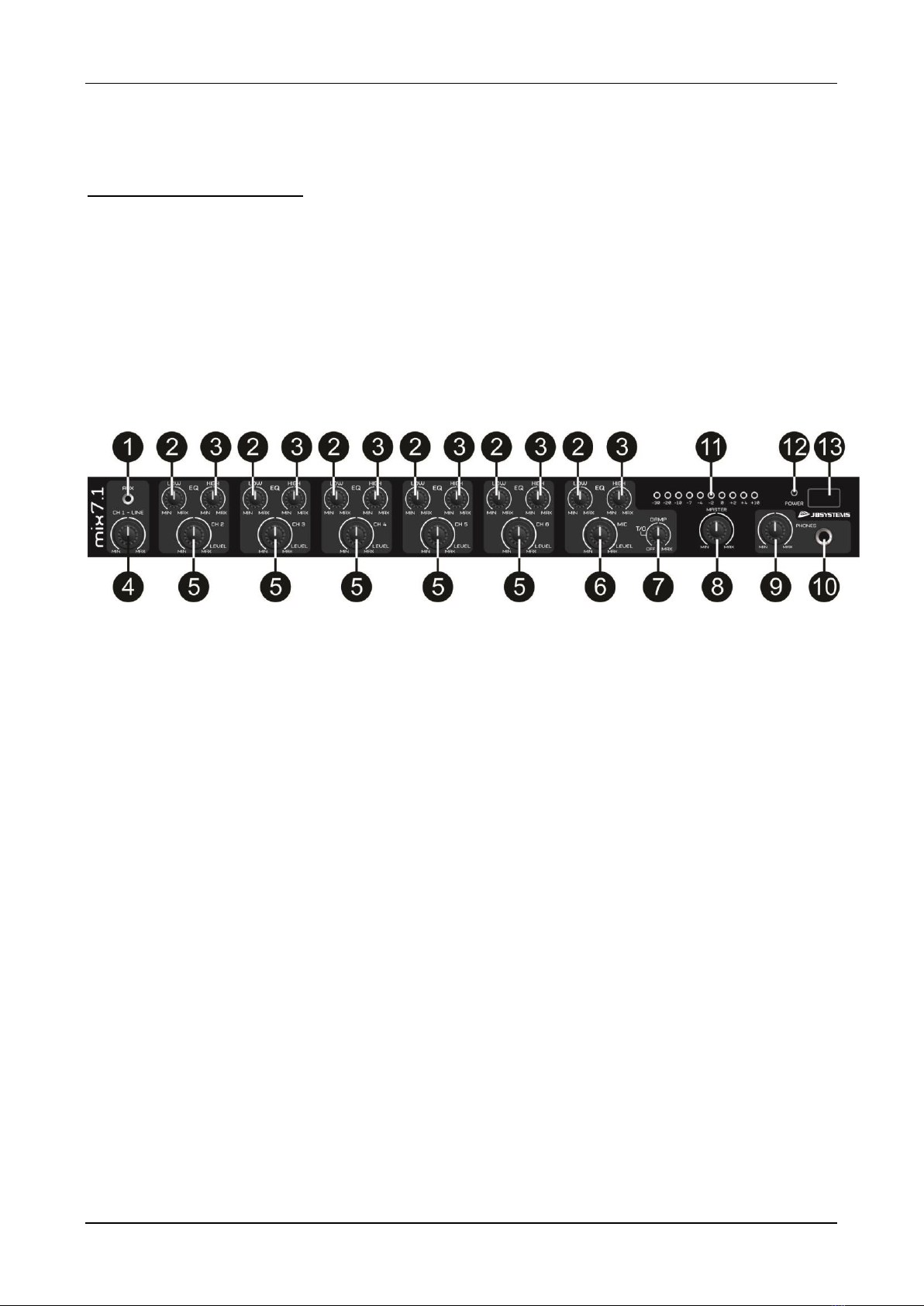
11. Master output level meter: Displays the output level set by the [master] level control (8). Note that the
setting of Max. level control (27) on the back panel does not affect the display of this meter.
12. Power LED: The LED is on when the unit is switched on.
13. Power switch: Switches the unit on and off. Make sure you switch the unit off when not in use.
FUNCTIONS (rear)
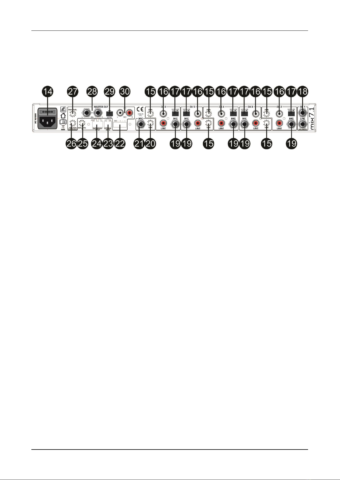
14. AC mains input and fuse holder: Use the supplied AC cord to connect the unit to AC mains. Make
sure voltage and frequency stated on the unit comply with your local AC supply. The fuse can be
accessed by the small drawer at the AC inlet. To change the fuse, unplug the AC cord first, pull out the
fuse drawer and replace the fuse ONLY with a fuse of SAME voltage and rating. If the fuse blows again
after replacement, hand over the unit to qualified service personnel for repair.
15. Gain control for the input: used to adjust the input sensitivity to compensate the different source
volumes.
16. Line inputs: These are line-level RCA/cinch inputs.
17. Source selector switch: allows you to select the desired input source for each channel. You can switch
between the line input (16) and the microphone input (19).
18. Balanced Line input: used to connect a balanced stereo line source to the unit (PA mixers, etc). Note
that the signal of these inputs is disabled when a connector is inserted to the front [AUX] input (1).
19. Microphone input: This is a balanced JACK-connector to connect a dynamic microphone. If needed,
the unit can be modified internally to provide phantom power for condenser microphones.
20. Gain control for the microphone input: used to adjust the input sensitivity to compensate the different
source volumes.
21. Microphone input: This is a balanced JACK-connector to connect a dynamic microphone. If needed,
the unit can be modified internally to provide phantom power for condenser microphones.
22. Balanced stereo master output: Balanced terminal block output carrying the same signal as output
(28), often used for fixed installations.
23. Music Mute input: This is a terminal block input which allows to remotely mute the masters by simply
shortening the contacts.
24. Emergency input: This is an auto-sensing, balanced terminal block input which allows the connection of
an emergency evacuation system. Once an audio signal is present on this input, all output signals will be
muted and the emergency message/signal from this input will become audible instead.
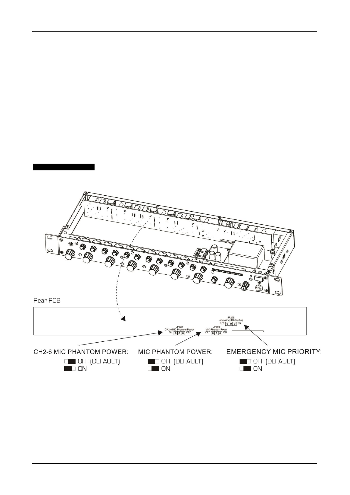
Microphone routing for muting/emergency: Depending on the application, user habits and local
safety requirements, it can be useful to either enable or disable the local microphone during an
emergency case where an incoming emergency signal into the emergency input (24) shuts down all
program signals. The advantage of disabling the microphones for this case is that the local user can
not interfere the legibility of the emergency announcement by using his own microphone, the
disadvantage is that if for whatever reason the emergency announcement does not stop, the local
user can still give emergency/evacuation guidance by means of the local microphone. As a factory
default, the microphones are not muted during an incoming emergency message. To change this, a
qualified installer or technician must open the unit after disconnecting it from AC supply. Refer to the
drawing to locate jumper “Emergency MIC setting” on the rear panel PCB: set the jumper in the
desired position..
25. Emergency volume control: This control sets the volume of the emergency input (24) sent to the
[MASTER] output.
26. Talkover adjustment: The talkover circuit make it possible to automatically damp the music while you
speak into the microphone that is connected to the dedicated microphone channel (21). There are two
controls to make sure that the talkover works as expected:
•Talkover Damping (7) on the front: adjusts the amount of damping once the talkover is active. If no
talkover effect is required the DAMPING control can be set to “off”.

ENGLISH OPERATION MANUAL
JB SYSTEMS®5/6 MIX 7.1
•Talkover Threshold (26) on the rear: adjusts when the talkover should start damping the music.
The higher the setting, the faster the talkover will come in action. Adjustments shall be made with a
small screw driver. Do not apply excessive force with the screw driver.
27. Maximum level setting for Stereo output: Used to limit the maximum output level for the general
output in order to match the maximum allowable sound levels of connected sound system. Adjustments
made on this control will not be displayed by the output level meter (11). Adjustments shall be made with
a small screw driver during installation. Do not apply excessive force with the screw driver.
28. Balanced stereo output: Balanced stereo JACK output carrying the main output signal controlled by the
master volume control (8).
29. Mono switch: used to convert the stereo output to simple mono for use with small background music
speakers in toilets, terraces, corridors, … The summed mono signal is available on both L and R outputs
(28)
30. Record output: This is an unbalanced stereo output carrying the same signal as the main outputs, but
not influenced by the main volume control (8). This is normally used for recording the output to an
external recording device.
INTERNAL SETTINGS
WARNING / DANGER: to change the internal settings for the microphone emergency signal and Phantom
power you will have to open the unit. This should only be done by a qualified technician. NEVER open the
unit when the unit is connected to the mains power. Always disconnect the mains cable before you open the
unit !
MICROPHONE PHANTOM POWER SETTINGS
Dynamic microphones are mostly used with this kind of unit, so Phantom Power is not needed.
If you would use condenser microphones, then you need Phantom Power to feed the microphones.
The MIX7.1 can provide this Phantom Power. It can be switched ON/OFF for the priority [MIC] input (21) and
it can be switched ON/OFF for all the other microphone inputs of Channels 2 to 6 (19). Please note tht the
Phantom Power for channels 2 to 6 can only be made globally, not individually.
EMERGENCY MIC PRIOROTY
When an external emergency signal is muting the outputs of the unit, you can decide if fhe connected
microphones should be also muted or if they need to remain active.
•OFF: when an emergency signal comes in, the microphones will also be muted (switched off)

ENGLISH OPERATION MANUAL
JB SYSTEMS®6/6 MIX 7.1
•ON: when an emergency message comes in, only the music will be muted but the microphones will
not be muted and can still be used.
OPERATION
IMPORTANT: before you connect the unit to the mains, check if the selected Voltage on the unit
corresponds to your available local Voltage
Don’t change the voltage switch while the unit is plugged in.
.
It is advised to always follow the same order to start up or to shut down the sound system.
To start up the sound system:
•First switch on all the audio sources
•Then switch on the mixer
•Always switch on as last the amplifiers or powered speakers
To shut down the sound system:
•Always switch off the amplifiers or powered speakers first
•Then switch off the mixer
•Finish by switching off all the audio sources
When units are switched on/off, it is advised to set the output level of each unit to zero
SPECIFICATIONS
This unit is radio-interference suppressed. This appliance meets the requirements of the current European
and national guidelines. Conformity has been established and the relevant statements and documents have
been deposited by the manufacturer.
Power Supply: AC 115V/230V, 50/60Hz
Power Consumption: max. 20W
Frequency response: 20-20.000Hz (+/-1dBu)
THD: <0.03% (Line)
S/N Ratio: >82dB (22Hz-22kHz)
Crosstalk Damping: >65dB (Line)
Dimensions: 483(W) x 44(H) x 152(D) mm (19” / 1U)
Weight: 2,3kg
Every information is subject to change without prior notice
You can download the latest version of this user manual on our website: www.jb-systems.eu

Table of contents
Other JB Systems Music Mixer manuals

JB Systems
JB Systems B4.2 MEDIAMIX User manual

JB Systems
JB Systems ME 2 User manual

JB Systems
JB Systems MM-IO User manual

JB Systems
JB Systems DE 600 User manual

JB Systems
JB Systems MM 14D User manual

JB Systems
JB Systems CD200 User manual

JB Systems
JB Systems PRO 16X User manual

JB Systems
JB Systems MX 100 User manual

JB Systems
JB Systems BEAT 4 Mk2 User manual

JB Systems
JB Systems ME 2 User manual