PHXLE
PHXL-SA
PHB-SA
PHS-SA
PHN-SA
PHBE DESPIECE PHB
PHSE
PHNE
14:15
20ºC
Power
45%
TC1
45ºC
Selected 120ºC
TC2
P100ºC
20ºC
TC3
P100ºC
20ºC
TC4
P100ºC
14:15
20ºC
Power
45%
Selected power
45%
TC1
P100ºC
20ºC
TC3
P100ºC
20ºC
TC4
P100ºC
20ºC
TC2
P100ºC
14:15
20 ºC
T1 23 ºC
20
5’ 8’
ºC
120 ºC
T3
24 ºC
T7
StopPROFILE1
200
100
14:15
31ºC27ºC
TC1 TC2
StopPROFILE1
200
100
14:15
200
150
100
50
300
250
14:15
5m 00s
120ºC
PROFILE1
200
100
14:15
30ºC
Power
45%
Selected power
45%
TC1
C100ºC
---ºC
TC2
P100ºC
0 60 120 180 240 300
Point
2/3
Temp Time
2m 00s
14:15
20ºC20ºC
TC1 TC2
20ºC
TC3
20ºC
TC4
StopPROFILE1
200
100
Ext. Temp [ºC]Power [%]
14:15
20ºC
Power
45%
TC1
45ºC
Selected 120ºC
TC2
P100ºC
20ºC
TC3
P100ºC
20ºC
TC4
P100ºC
14:15
20ºC
Power
45%
TC1
45ºC
Selected 120ºC
Max. Rate
1.6ºC/s
Max. Rate
1.6ºC/s
TC2
C100ºC
20ºC
TC3
P100ºC
20ºC
TC4
P100ºC
14:15
20ºC
Power
45%
Selected power
45%
14:15
TC5
P100ºC
20ºC
TC7
P100ºC
20ºC
TC8
P100ºC
20ºC
TC6
P100ºC
20ºC
TC5
P100ºC
14:15
20ºC
Power
45%
TC1
25ºC
Selected 120ºC
TC2
P100ºC
14:15
20ºC
Power
45%
TC1
25ºC
Selected 120ºC
TC2
P100ºC
14:15
20ºC
Power
45%
TC1
45ºC
Selected 120ºC
TC2
C100ºC
20ºC
TC3
P100ºC
20ºC
TC4
P100ºC
20ºC
TC5
P100ºC
20
5’ 8’
ºC
120 ºC
80 ºC
100 ºC
5’ 8’5’30”3’30” 8’
20 ºC
120 ºC
80 ºC
TC1 TC2 TC3 TC4
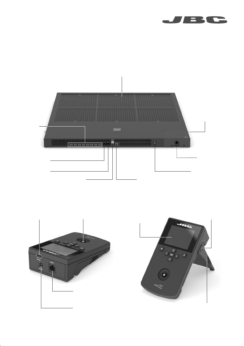
ROBOT AUX. PEDAL
Hot
Zone B
Zone A
Zone A
Zone B
Hot
Hot
Zone B
Zone A
Zone A
Zone B
Hot
TC1 TC2 TC3 TC4
ROBOT AUX. PEDAL
TC1 TC2 TC3 TC4
ROBOT AUX. PEDAL
TC1 TC2 TC3 TC4
ROBOT AUX. PEDAL
Hot
Zone B
Zone A
Zone A
Zone B
Hot
Hot
ZoneB
Hot
ZoneB
ZoneA
ZoneA
Max. Rate
1.6ºC/s
Max. Rate
1.6ºC/s
Max. Rate
1.6ºC/s
Max. Rate
1.6ºC/s
Work mode
Mode
Time to stop
Thermocouples
Max Rate
Back
None
2min
Temp.
14:15
Work mode
Mode
Time to stop
Thermocouples
Max Rate
Back
None
2min
Temp.
1.6ºC/s
Max Rate
Min 0.1ºC/s Max 2.0ºC/s
C
P
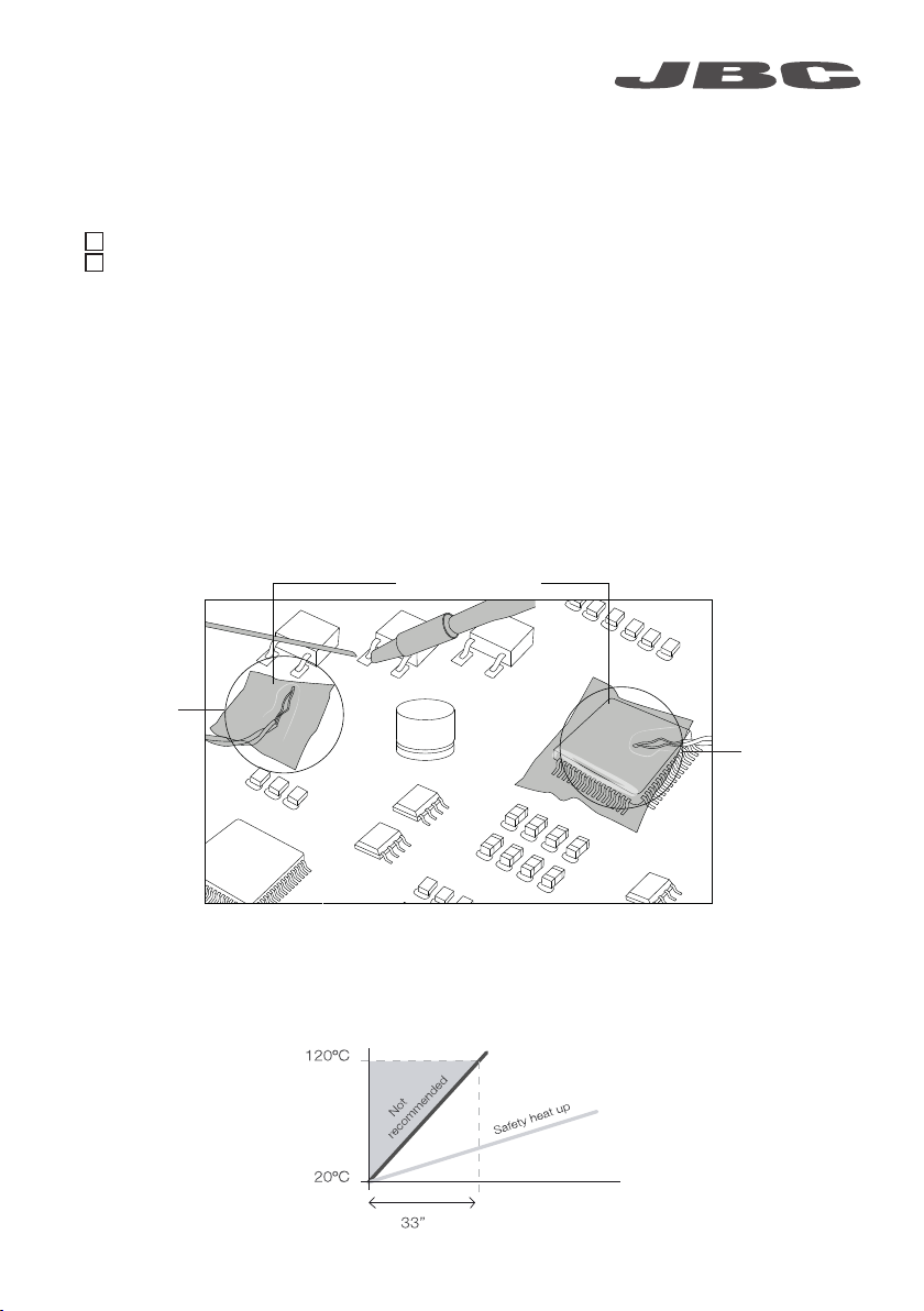
Recommended Guidelines
1. Place the control thermocouple as near as possible to the component being worked on.
2. If there are any sensitive components, use a thermocouple as protection.
You can select the protection temperature in the thermocouples menu. If the selected temperature
is reached, the Heater Unit will stop the process and a warning message will be shown.
3. IPC* does not recommend exceeding ramp-up rates over 3 - 4 °C / sec (5 - 7 °F / sec) so as to
reduce the risk of thermal stress on the PCB.
* IPC was founded in the U.S. in 1957 as the Institute for Printed Circuits and is committed to becoming the
most recognized international industry association for the electronics manufacturing industry.
Fix with Kapton Tape
Protection
Thermocouple
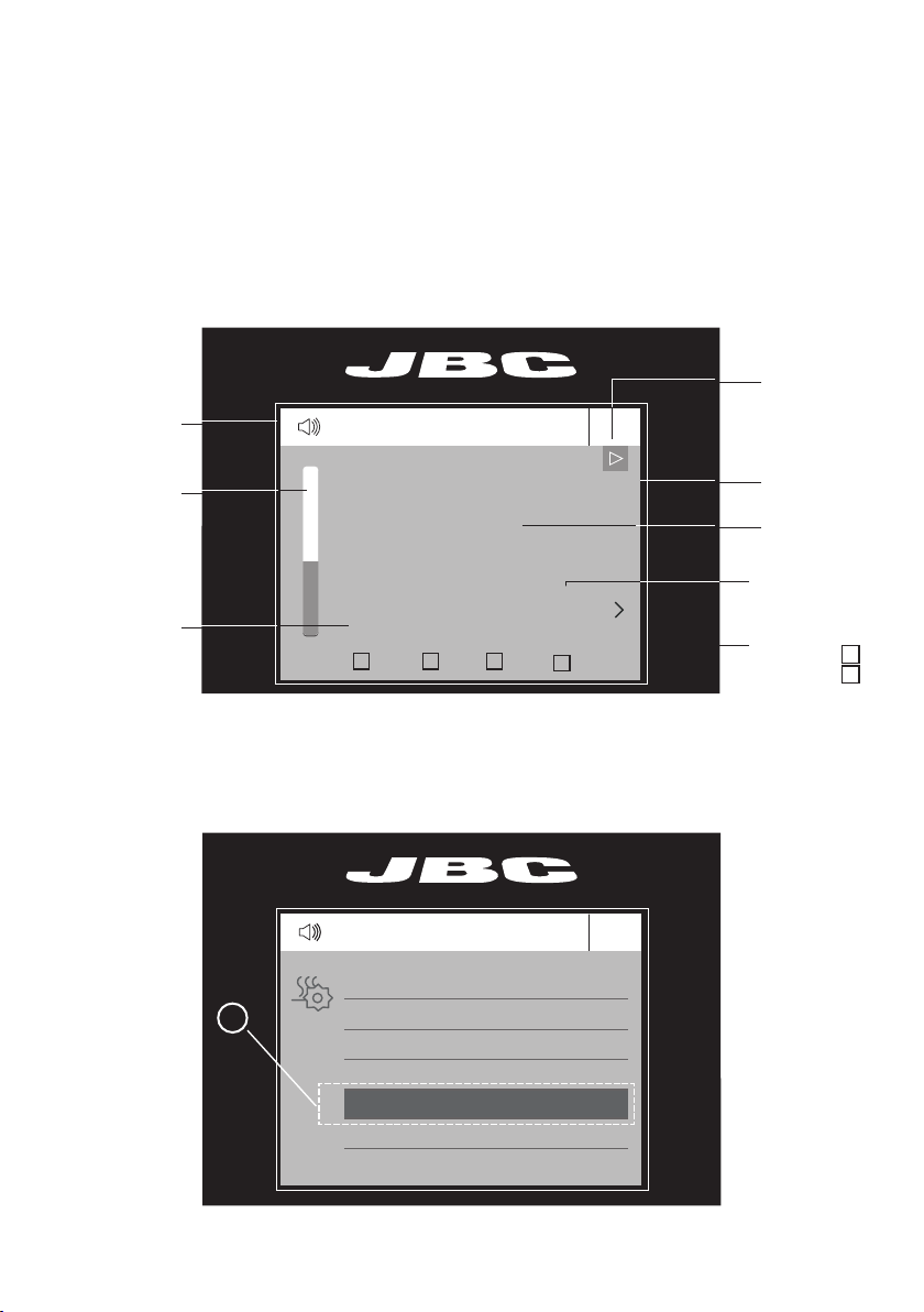
Setting Thermocouples Function
Select Thermocouples from the Work mode menu to set them up.
The thermocouples (TC) can work in three diferent ways depending on what is needed.
· Control: the unit mantains the selected temperature.
· Protection: the Heater Unit stops if the TC reaches the selected temperature.
· Info: the TC temperature is shown in the work screen.
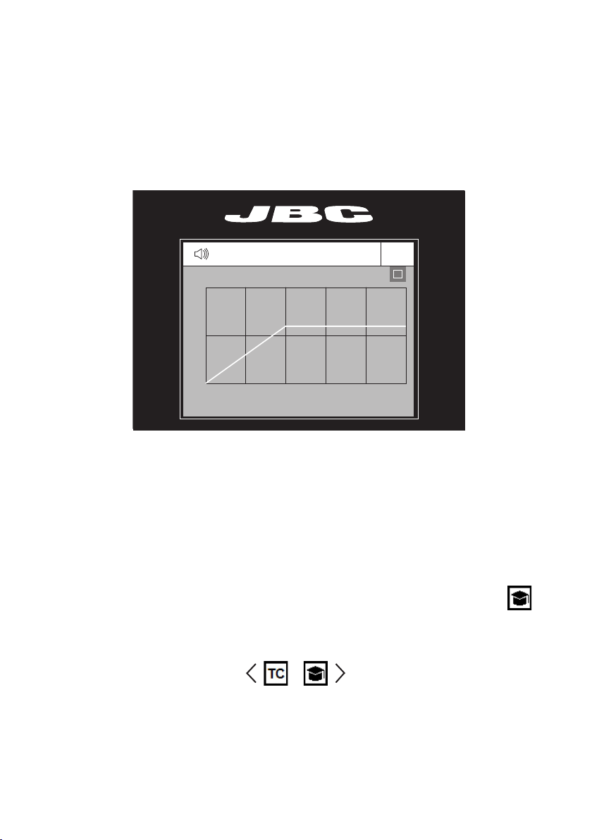
The TC1 is always working in Control mode for the Temperature mode as well as for Profiles mode.
The temperature of each TC can also be selected from the work screen.
Control
Thermocouple
7
www.jbctools.com