7
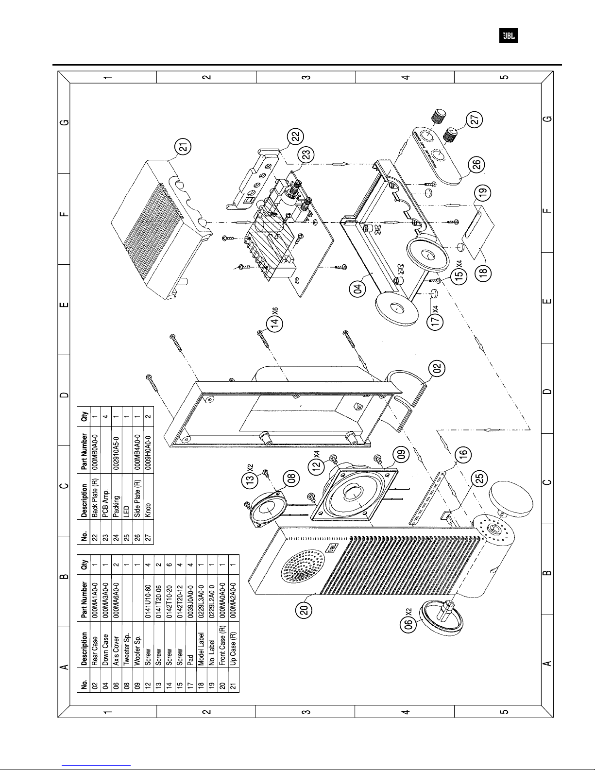
Two-Way Speaker System Media 2
REF. NO. PART NO. DESCRIPTION QTY
Transistors
Q101, 102 1020945161 2SC945P 4
103, 104
Diode
D101, 102 125200032 IN4148 2
Diode (Zener)
ZD101, 102 1253000022 1/2W 9.1V (MTZ9.1B) 2
Diode (LED)
LD101 1257000041 2x5 m/m ED/G EEN 1
Integrated Circuits
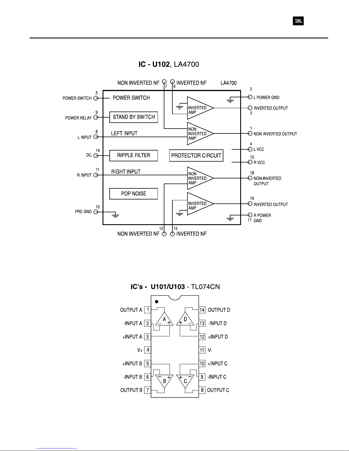
U101, 103 1281000021 TLO74CN OP AMP 2
U102 1281000031 LA4700 POWE AMP 1
Resistor (Car on)
101, 102, 103, 1312033361 1/4W 33 KΩ±5% 4
104
105, 106 1312056361 1/4W 56 KΩ±5% 2
107, 108 1312012361 1/4W 12 KΩ±5% 2
109, 110, 111 1312010361 1/4W 10 KΩ±5% 11
112, 123, 124,
130, 148, 149,
153, 156
113, 114, 115, 1312027261 1/4W 2.7 KΩ±5% 4
116
117, 118 1312015161 1/4W 150 Ω±5% 2
119, 120, 121 1312010161 1/4W 100Ω±5% 5
122, 134
125, 126, 127, 1312022961 1/4W 2.2 Ω±5% 4
128
129, 150 1312022361 1/4W 22 KΩ±5% 2
131 1312033061 1/4W 33 Ω±5% 1
132 1312010061 1/4W 10Ω±5% 1
133 1312015261 1/4W 1.5 KΩ±5% 1
135, 136, 137, 1312010461 1/4W 100 KΩ±5% 5
138, 147
139 1312015461 1/4W 150 KΩ±5% 1
140, 141 1312022261 1/4W 2.2 KΩ±5% 2
142 1312018561 1/4W 1.8 KΩ±5% 1
143 1312018461 1/4W 180 KΩ±5% 1
144, 152 1312033161 1/4W 330 Ω±5% 2
145 1312039461 1/4W 390 KΩ±5% 1
146 1312082461 1/4W 820 KΩ±5% 1
151 1312068261 1/4W 6.8 Ω±5% 1
154 1312010261 1/4W 1 KΩ±5% 1
155 1312068161 1/4W 680 Ω±5% 1
Capasitors (Electrolitic)
C101, 102, 103, 1546105112 50V 1 µF85°C ±20% 8
104, 111, 112,
113, 114
C117, 118, 119, 1542107112 10V 100 µF85°C ±20% 8
120, 121, 122,
128, 132
C129 1544107112 25V 100 µF85°C ±20% 1
REF. NO. PART NO. DESCRIPTION QTY
C130 1544228111 25V 2200 µF85°C ±20% 1
C131 1546475112 50V 0.47 µF85°C ±20% 1
C134, 138 1546106112 50V 10 µF85°C ±20% 2
C135, 136 1542227112 10V 220 µF85°C ±20% 2
Capasitors (Polyester)
C107, 108, 109, 1631683420 50V 0.0068 µF ±10% 4
110
C115, 116 1631472420 50V 0.0047 µF ±10% 2
C123, 124, 125 1631104420 50V 0.1 µF ±10% 4
126
Capasitors (Ceramic)
C105, 106 1723470142 50V 47PF CH ±5% 2
C133 1733221152 50V 220PF B ±5% 1
C139, 140 1733472272 50V 0.0047 µF F +8~-20% 2
C141 1733101142 50V 100PF CH ±5% 1
VR (Rotary)
V 101A, B 1951032402 10KBX2 1
V 102A, B 1951031601 10KAX2 1
PCB
2001300300 PCB, FIGU ED 1.6T 94V-0 1
Speakers
2110040204 1-3/4" PEIZO SPEAKE 2
2110075303 12Ω3" SHIELDED SPEAKE 2
Wires
2286053803 VINYL COAT WI E 380-5-5 1
AWG24 UL1007 BLUE
2284053803 VINYL COAT WI E 380-5-5 2
AWG24 UL1007 YELLOW
P103A, B 2282062203 VINYL COAT WI E 220-5-5 1
AWG26 UL1007 ED
P104A, B 2285062203 VINYL COAT WI E 220-5-5 1
AWG26 UL1007 G EEN
P105A, B 2280062203 VINYL COAT WI E 220-5-5 1
AWG26 UL1007 BLACK
J101, 102, 111 2350607500 JUMPE WI E 0.6∅- 7.5 11
113, 115, 116,
117, 118, 119,
120
J103, 104, 109, 2350610000 JUMPE WI E 0.6∅-10 5
110, 112
J105, 106, 107 2350615000 JUMPE WI E 0.6∅-15 4
114
B101A, B 2360100002 CONNECTIVE CO D 1
5C-100 AWG26 UL1007
B102A, B 2360130001 CONNECTIVE CO D 1
4C-130 AWG26 UL1007
Jacks
JK101, 102, 103 2460103003 JACK (EA ), 3
3P ST-3.5∅-3P LJE0361-3 T
JK104 2460801004 JACK (DC) 2.0 DIA DC-014 1
JK105 2460601001 JACK ( CA), 1
1P J-1034-30BL-02
2460601002 JACK ( CA), 1
1P NUT TYPE SCJ-0363B
ELECTRICAL PARTS LIST