JBL EON10 G2 User manual

EON10 G2 User Guide
Part Number:981-00061-01
CEV.FR

Applications
•Live sound reinforcement, speech and vocals, music playback in entertainment, A/V, and institutional
venues-especially when ease of use and portability are important factors.
•Amplification, mixing, and monitoring for electronic musical instruments.
Features
The second generation of one of the most successful and influential professional speaker systems ever.
•10”Differential Drive®low-frequency driver with a neodymium magnet for low-distortion and light weight.
•1”(throat diameter) JBL compression driver with titanium diaphragm and ferro-fluid cooling.
•Bi-amplified 125 watts low frequency and 50 watts high frequency - actual power delivered to the drivers.
•Built-in 3-input mixer.One balanced mic / line selectable input, one dual-channelTRS 1/4”phone line-level
•Balanced loop-through / mix output.“Daisy-chain” additional EON speakers or send the mixed output to a
mixing console or auxiliary EON speaker.
•90° x 60° (nominal) constant directivity horn.
•Thermomaster®TotalThermal Management System®. A single piece, cast-aluminum baffle integrates the
woofer frame, horn, and amplifier heat sink.Air movement in the finned ports dissipates heat - no internal
or external cooling fans are required.
•Rugged, lightweight, black co-polymer enclosure with an ergonomic molded in handle and cast
aluminum baffle.
•Integral 35 mm pole mount receptacle with securing thumbscrew.
•Multi-angle enclosure for front of house or stage monitor application.
Specifications
Freq.Range (-10 dB): 65 Hz - 18 kHz
Freq.Response (±3 dB): 90 Hz - 16 kHz
Horiz.Coverage (-6 dB): 90° nominal
Vert.Coverage (-6 dB): 60° nominal
Rated Maximum SPL: 117 dB, @ 1 m (3.3 ft)
Dimensions (H xW x D): 493 mm x 356 mm x 307 mm (19.4 in x 14.0 in x 12.1 in.)
NetWeight: 10.4 kg (23 lbs.)
LF Driver: Integral frame with one 10” (254 mm) driver, dual neodymium magnet,
1.5”Differential-Drive®voice-coil.
HF Driver: JBL2412 1”(throat diameter) compression driver with titanium diaphragm.
Ferro-fluid cooled.
Amplifier Power LF: 125 watts @ low-frequency driver impedance.
Amplifier Power HF: 50 watts @ high-frequency driver impedance.
Input 1 Sensitivity: -48 dBu to 0 dBu for rated output (Mic/Line switch in MIC position)
-6 dBu to +20 dBu for rated output (Mic/Line switch in LINE position)
Input 2 & 3 Sensitivity: -12 dBu to +20 dBu for rated output
Output Level: +26 dBu (peak), Loop/Mix switch in MIX position
Audio Connectors Input 1: XLR/F, balanced
Audio Connectors Input 2 & 3: SingleTRS 1/4”Phone
Crossover Freq: 2.7 kHz
Loop/Mix Out: XLR/M, balanced.
AC Input: 110 - 230VAC, 50 - 60 Hz, 100 watts rating per UL, detachable IEC
power cable
6
About The EON10 G2

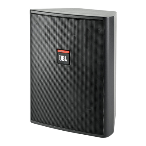
Frequency Reponse
Available Accessories
SS2-BK Tripod Stand
ESK10 Suspension Kit for EON 10” models
BRK10 Bracket, adapts EON 10”models to OmniMount®brackets
EON10 Bag-1 Zippered, plushed-lined speaker bag for EON 10” models
Block Diagram
7

8
1. Refer to the “Basic Sound Reinforcement System with Stage Monitors” diagram on page 12
2. Turn the INPUT 1 and INPUT 2 & 3 controls fully counter clockwise.
3. Set the MIC/LINE switch.
• If a microphone will be connected directly to INPUT 1, set the MIC/LINE switch to the MIC position (depressed).
The MIC LED will illuminate when power is turned on.
• If a mixer, CD player, cassette tape, or electronic musical instrument (the“source”) will be connected directly to
INPUT 1, set the MIC/LINE switch to the LINE position (disengaged).The MIC LED will not illuminate when power
is turned on.
4. Plug the power cable into a properly grounded 3-wire AC power.
5. Plug the XLR cable from the mixer or microphone into the INPUT 1 connector.
6. Connect unbalanced sources (if used) to the INPUT 2 & 3 connector.
7. POWER UP PROCEDURE
First, switch on the power to the mixer, audio sources, or musical instruments that are feeding your EON10 G2.
• Next, turn on the power switch (the front panel power indicator will illuminate).
• Reverse this process when shutting down your system.This will avoid disturbing thumps from the speaker as
sources power on/off.
8. SETVOLUME
• If you are using an audio-mixing console, refer to the manufacturer’s instructions to properly set gain structure
(see the “Gain Structure”section on page 16).
• Turn up your sources to the level that will be used in performance and talk, sing or play into the system.
• Bring the INPUT 1 control up (clockwise) until the desired volume has been reached. If you are using a micphone,
turn the INPUT 1 control up slowly to avoid feedback.
• If you are using the INPUT 2 & 3 inputs, bring the INPUT 2 & 3 controls up to the desired volume.
9. CHECKTHE PEAK LED -The PEAK indicator flashes when the loudspeaker’s on-board amplifiers are approaching
maximum output.Occasional flashes are normal for very loud operation.However, if the PEAK LED stays
illuminated, the sound will be distorted and it is an indication that more speakers or a lower performance volume
may be required for your specific application.
CONTROLS AND CONNECTIONS
The audio section of the EON10 G2 includes powerful features that enhance the flexibility of your speakers.
Controls
INPUT 1
Adjusts the level of INPUT 1.Use this control to match the input sensitivity of the EON10 G2 to the
output level of the mixer, microphone, or instrument connected to INPUT 1.It is a common miscon-
ception that this control changes the power of a system.Your EON10 G2 will produce its rated output
power no matter where this control is set.The INPUT 1 control determines how much signal is
required at the input in order to drive the system to full output.
INPUT 2 & 3
This control adjusts the level of the inputs connected to INPUT 2 & 3.
Quick Start
LINE
MIC
O
U
T
P
U
T
1
I
N
P
U
T
LOOPMIX
R-PEAK
G-SIGNAL
1
2 & 3
2 & 3
2
3

LINE
MIC
O
U
T
P
U
T
1
I
N
P
U
T
LOOPMIX
R-PEAK
G-SIGNAL
1
2 & 3
2 & 3
2
3
Connectors
INPUT 1
This balanced input accepts a standard XLR (female) connector.A broad range of signals from
microphones (-48 dBu to 0 dBu nominal), audio mixing consoles, and electronic musical
instruments may be connected here.When using a single audio input to the speaker, this is the
input to use.The sensitivity of this input is controlled by the MIC/LINE SWITCH and the INPUT 1
rotary control.
INPUT 2 & 3
This 1/4”jack can accommodate one or two channels of audio.When a two-channel source is
connected by means of aTRS 1/4” plug, both channels are summed to mono.A single channel
source may also be connected here with a standard 1/4”TS plug.This input is intended for use
with audio devices including cassette tape, CD, MP3 players, computer sound-card outputs,
electronic keyboards, and electric/acoustic musical instruments.The level of INPUTS 2 & 3 is
controlled by the INPUT 2 & 3 rotary control.See the APPLICATION EXAMPLES and CABLES
AND CONNECTORS sections of this guide for details on how this input may be used.
OUT
This XLR (male) output connector works with the MIX/LOOP SWITCH (see below) to provide a
method of sending audio from your EON10 G2.
Switches
MIC/LINE
The MIC/LINE switch effects only INPUT 1.It selects between two sensitivity ranges.This switch
is used to match the input sensitivity of the EON10 G2 with the output level of the device connected
to INPUT 1.Depressing the MIC/LINE switch selects MIC (most sensitive) and causes the MIC/LINE
LED to illuminate.
CAUTION:Before adjusting this switch, be certain to rotate the INPUT 1 control fully counter clockwise.
After the MIC/LINE switch has been adjusted, slowly rotate the INPUT 1 control clockwise until the
desired volume has been reached.
• Use the MIC position (depressed) when a microphone is connected to INPUT 1.
• Use the LINE position (disengaged) when a line level source such as an audio mixing console,
audio playback device, or electronic musical instrument is connected to INPUT 1.
MIX/LOOP
This switch selects the source of the signal for the OUT connector.
CAUTION: Before adjusting this switch, be certain to set the input level control of any equipment connected to this
output to its minimum gain (least sensitive) setting.
• In the disengaged position, only the signal from the INPUT 1 connector is routed directly to the OUT connector.
Changing the other settings on the audio panel will not effect the OUT signal.The INPUT 2 & 3 inputs will not
be present at the OUT connector. Use this setting when you want to feed multiple EON powered speakers the
same signal.
• In the MIX position (depressed), a blend of all inputs to the speaker (INPUT 1 and 2 & 3) will be sent to the
OUT connector.Any changes to input level settings will affect the OUT signal.See the APPLICATION
EXAMPLES section for details on how this mode may be used. 9

LINE
MIC
O
U
T
P
U
T
1
I
N
P
U
T
LOOPMIX
R-PEAK
G-SIGNAL
1
2 & 3
2 & 3
2
3
10
Indicators
PEAK / SIGNAL
The PEAK / SIGNAL LED (Light Emitting Diode) is a two-color device.Red indicates that the
system is approaching clipping.The threshold for this light is actually about 2 dB below clipping.
An occasional flicker of the red LED on the loudest peaks is acceptable.If this LED remains red
for more than the duration of brief dynamic peaks, the system is being overdriven.Continuously
over driving the system will result in unpleasant and fatiguing distortion and may lead to premature
failure of your speaker system.
If the red LED illuminates excessively:
• Reduce INPUT 1 and INPUT 2 & 3.
• Reduce the output level of the mixer, musical instrument, or other source to the speaker.
Green indicates a usable signal is present at INPUT 1 and/or INPUT 2 & 3.
MIC
This LED illuminates to indicate that the MIC/LINE switch is in the MIC (depressed) position.
VOLTAGE SELECTION AND FUSES
ChangingVoltage
Your EON10 G2 will typically be set at the factory to accommodate the power mains voltage in your area.Before
you set up your EON10 G2 for the first time it is a good idea to verify that the setting of the selector is appropriate
for the power in your area.Directly above the power switch you will see a seal that indicates the factory setting for
the voltage.If the voltage indicated is correct for your area, go ahead and power up your EON10 G2.
In the event that you do need to change the voltage selection:
• Make sure that the AC is disconnected from the speaker.
• Directly above the power switch on the speaker is a voltage selector.Peel off the
factory-applied seal.
• Set the voltage selector switch to the 115V or 230V setting as required for your area.
• After having reconfirmed that the correct voltage is selected, connect the AC
(IEC connector) and power the unit up.
DO NOT UNDER ANY CIRCUMSTANCES OPERATETHE UNIT WITH THE WRONG
VOLTAGE SELECTED.DOING SO MAY RESULT IN SERIOUS DAMAGETOYOUR
SPEAKER SYSTEMWHICH WILL NOT BE COVERED BYWARRANTY.
Fuse Replacement
The EON10 G2 has no user-serviceable fuses.Failure of fuses is most frequently a symptom of problems requiring

service by a competent technician.

11
Application Examples
One Piece PA System
In this basic PA setup a dynamic microphone is connected to INPUT 1.The MIC / LINE switch would be
set to the MIC position (depressed).Several examples illustrating possible uses for INPUT 2 & 3 are
shown.
Acoustic Electric Guitar - The mono or stereo output of an electrified acoustic guitar can be connected
directly to INPUT 2 & 3.If a stereo instrument and cable are used, the left and right channels will be
combined into mono.
Electronic Keyboards - A pair of electronic keyboards are connected to INPUT 2 & 3 via an adapter cable
(see the section “Cables and Connectors”).Such a cable is available from pro-audio dealers and is
commonly used as an “insert cable”.
Portable CD Player - A portable CD player may be connected to the EON10 G2 by means of a 1/4”TRS
to Mini-Phone adapter.Again, the left and right channels will be combined into mono.
LINE
MIC
O
U
T
P
U
T
1
I
N
P
U
T
LOOPMIX
R-PEAK
G-SIGNAL
1
2 & 3
2 & 3
2
3
1/4” TS Phone 1/4” TS Phone
1/4” TS Phone
1/4” TS Phone
1/4” TRS Phone
1/4” TRS Phone
to
Mini-Phone
Adapter
1/8” TRS Phone
1/8” TRS Phone
Portable CD
Pla
y
er
Acoustic
Electric
Guitar
Dynamic
Microphone
Electronic Keyboards

12
Basic Sound Reinforcement SystemWith Stage Monitors
This is the basic live sound system.The optional tripod stands will get the speakers up above the
audience so the sound can project.The second pair of EON10 G2 speakers are used as stage monitors.
For maximum gain before feedback, position the monitors so that they do not point into microphones.
The output connectors on your mixer may differ from the illustration.
DJ or Sound Reinforcement System with EONSUB G2
Here’s a system with EONSUB G2 added to provide additional low-frequency power.If your mixer has a
SUM or MONO output, you can also drive the EONSUB G2 from this output and use the SUM or MONO
volume control for independent control of bass.
INPUT 1 INPUT 1
TYPICAL MIXER INPUT / OUTPUT PANEL

13
DJ System with Passive Subwoofers
This system combines a pair of EON10 G2 powered speakers with externally powered subwoofers for
extra power at very low frequencies.
* Recommended crossover frequency = 80-150 Hz.(season to taste)
INPUT 1 INPUT 1
DJ Mixer
Amplifier
Low Pass Output - Left
Output - Left Output - Right
Low Pass Output - Right
High Pass Output
Left
High Pass Output
Right
dbx® DriveRack™ PA*
Symptom Likely Cause What to do
No sound Speaker not connected to active Verify that speaker is connected and
AC power. that the circuit is on.
Power not switched on. Switch on power and verify that power
LED is on.
No sound, speaker is Speaker power cable is faulty or Re-seat the power cable at both ends.
connected to working improperly connected. Substitute a known-good power cable
AC power but won’t come on. Blown fuse. There are no user-serviceable fuses in
the EON10 G2.Take your speaker to a
competent servicer.
Troubleshooting

14
Troubleshooting
Symptom Likely Cause What to do
No sound.Speaker comes on. Signal source (mixer, instrument, CheckVU meters on the source
SIGNAL LED does not etc.) is not sending. mixer.
illuminate. Verify that the tape or CD is playing.
Use headphones to verify that the
instrument is actually sending an
audio signal.
Faulty cables and connections. Disconnect and re-seat signal
cables.
Replace suspected cable with a
known-good cable.
No sound with microphone Microphone requires phantom The EON10 G2 does not supply
connected directly to the MIC / power. phantom power.Switch to a
LINE 1 input.SIGNAL LED dynamic microphone, use a
does not illuminate. battery in the microphone (if
possible), use an external
phantom power supply.
Signal sounds distorted and very Excessive input signal, Reduce the output level of the
loud, PEAK light is lit most of exceeding the capabilities source.
the time. of the speakers. Turn down the LEVEL controls
on the speaker.
Use additional EON speakers.
Signal sounds distorted even at Mixer or other source is Review the Owner’s Manual for
moderate volumes, PEAK light is overdriven. your mixer and adjust controls as
not lit. needed.
• Input sensitivity (gain)
• Channel faders
• Master faders
Once this is done, review the
instructions in the Quick Start
section of this guide.
Lots of hiss in the sound, the Improper gain structure or noisy Make sure that the MIC/LINE
mixer controls are at very low source device. switch is in the LINE
settings. (disengaged) position.
Reduce the LEVEL settings at the
speaker.
Review the Owner’s Manual for
your mixer and adjust controls as
needed.
Noise or hiss heard at output. Noisy source device. Disconnect the devices that are
connected to your speaker one at
a time.If the noise goes away, the
problem is with the source or the
connecting cable.

15
Symptom Likely Cause What to do
Hum or Buzz that increases or Improper A/C ground or faulty Disconnect or mute channels one
decreases when the mixer level equipment connected to mixer at a time to isolate the problem.
controls are moved. input. Refer to the Owner’s Manual of
the faulty equipment for
troubleshooting help.
Faulty cable between source Substitute a known-good cable
equipment and mixer. for the suspected faulty cable.
Hum or Buzz. Improper A/C grounding, ground Connect all speakers to a
loops. common power circuit.
“Telescope” the audio ground by
using an XLR/F to XLR/M
adapter with Pin 1 disconnected.
Re-route audio cables away from
AC power and lighting cables.
Excessively long unbalanced Use the balanced outputs (if
cable run. available) of your mixer or source
equipment to drive your EON
speakers.
Use a “DI” (direct injection) box
to convert your unbalanced
equipment output to a balanced
output.
Improper system gain structure. Reduce the INPUT 1, LINE 2,
and LINE 3 controls and increase
the output level of your source
devices.
The inputs from INPUT 2 & 3 MIX/LOOP SWITCH set Set the MIX/LOOP SWITCH to
aren’t coming out of the improperly. the MIX OUT position
OUT connector. (depressed).See the CAUTION
in the “Switches” section of this
manual.
The speaker connected to the MIX/LOOP SWITCH set Disengage the MIX OUT switch.
OUT connector goes up and improperly. See the CAUTION in the
down in volume when I adjust “Switches”section of this
the INPUT 1 control on the 1st manual.
speaker.
Speakers feedback and howl Microphones are pointed into the Move the speakers so they do not
when the microphone volume is speakers. point into the microphone’s pick-
turned up. up pattern.See the section on
“Loudspeaker Placement and
Mounting”on page 20.
Equalizer settings are incorrect. Locate the feedback frequency
and reduce it using the mixer EQ
or an external equalizer.
Excessive gain. Reduce the gain at the mixer and
move the microphone closer to
the sound source.

Gain Structure
Gain structure is the term we apply to adjusting the relative input sensitivity and output levels of
components in an audio system.The objective of proper gain structure is to minimize noise on one extreme and to pre-
vent clipping on the other.Proper gain structure will result in all components clipping at about the same time.
First, let’s clear up one common misconception.The input control on an amplifier or powered speaker does not deter-
mine how much power it will produce.A 100 watt amplifier (for example) can produce 100 watts no matter where the
input level control is set.The input level control simply determines how much input voltage is required to drive the amp to
full output.If the input level controls of an EON10 G2 are set too low (rotated too far counter-clockwise) the mixer will go
into clipping before the speakers are driven to full output.If the input level controls of an EON10 G2
are set too high (rotated too far clockwise) the system will be noisy.With that in mind, here’s a
procedure for setting up system gain structure that will get the best dynamic performance possible from your system.
Summary
• Adjust your mixer so that the loudest passages of your performance drive the mixer almost to its peak output.
• Set the MIC / LINE switch to the LINE position (unless a microphone is connected directly to the EON input).
Slowly bring up the INPUT 1 level control of the EON10 G2 until the desired performance volume is reached.
When used with a typical DJ or audio mixer, this will probably place the control around 10:00 o’clock.
Step by step instructions
1. Begin with all level controls on your mixer and EON10 G2 speakers at minimum. Note that the EON10 G2 has a
switch that selects “Mic”or “Line”sensitivity. The “Mic” position should be used only when a microphone is
connected directly to the input.
2. Bring the INPUT 1 level control on your EON10 G2s to approximately 9:00 o’clock. We’ll come back and make
some final adjustments here later on.
3. Bring the output of any electronic source (CD player, drum machine, electronic keyboard, etc.) to its “nominal”
position.This will usually be marked.If it isn’t, bring the control to about 2/3 of its maximum position. Make sure
that any foot pedals or other volume controls are at the position they will be during the performance.
4. At your mixer, bring the “Input Attenuator” (sometimes called“Gain”or “Sensitivity”) control up while playing the
instrument or talking / singing into the microphone. Be sure that the level you’re playing at is the same as the
actual performance level will be. Watch the channel “Clip”or “Overload” or “Peak” indicator.It should just flicker
on the very loudest dynamic peaks.
5. Now bring the channel fader up to its “nominal” position (see the mixer Owners Manual).
6. Slowly bring the mixer master faders up to their nominal position. At this point, you should hear sound from the EON10
G2s. If the level is too high, trim back the INPUT 1 control on the EON10 G2s.
7. Repeat steps 3 – 5 for all remaining channels.
8. Check the meters on the mixer output. If you’re seeing peaks that drive the meters into clipping, trim back the
channel faders and master faders slightly. Also be aware that actual performance levels tend to be higher than
rehearsal and sound check levels so you may want to trim back the input sensitivity slightly.
9. If an outboard processor such as a graphic EQ is used, it should be set to “unity gain”(see the processor’s
Owners Manual). Unity gain means that the signal level on the output is the same as the level at the input.
10. Now bring up the input control of your EON10 G2 speakers until the desired performance
volume is reached. If clipping occurs before the desired volume is reached you need more speakers or a lower
performance volume.
11. Listen to your mix and adjust to taste.
12. At this point, the maximum output of the mixing console should be capable of driving your EON10 G2s to full out
put and you will have the lowest noise operation that your equipment is capable of delivering.
16
Reference

Connections - Balanced and Unbalanced
There are two basic types of audio system interconnections for very low to medium level audio
signals:Balanced and unbalanced.Your EON10 G2 can accept either type of input.
Balanced Lines
In audio, a balanced line is a three-conductor system in which the two signal wires carry an equal, but opposite voltage
with respect to the ground wire.The ground wire acts only as a shield and does not carry any audio signal current.
Outside interference (such as RFI _Radio Frequency Interference) is either shielded from the internal signal conductor,
or if it gets into the cable, is
cancelled out by the opposite signals at the receiving end.Balanced connections are preferred
for any longer cable runs.
Unbalanced Lines
Unbalanced cable is a two-wire system where the shield (ground wire) acts as one of the current carrying signal conduc-
tors.The center conductor enclosed by the shield is commonly known as the “hot” conductor.Unbalanced audio cables
do not reject noise as well as balanced lines.Unbalanced lines are typical in home hi-fi type systems and on the outputs
of electronic musical instruments.These work well if the distance between the components is short, the signal level is
relatively high and all of the electronics used in the system are plugged into the same AC service.
Unbalanced Sources to EON Powered Loudspeakers
If you need to connect your EON speakers to an unbalanced source you have two options:
• Use the INPUT 2 and INPUT 3 connectors.These inputs are balanced but will accept unbalanced inputs without the
need for any special adapters.
• Use an adapter or special cable (see the section“Cables and Connectors”).
Loudspeaker Placement and Mounting
The following guidelines will help you achieve optimum sound wherever you use your EON loudspeakers:
Raise the speakers as high as possible.For best results try to get the high frequency horn at least 2 to 4 feet above the
heads of the audience.If the speakers are too low, the people in the back of the audience will not receive the best
quality of sound.
Place the speakers between the microphones and the audience.Feedback occurs when the microphones pick up sound
from the speakers and“feed” the sound back through the sound system.If space is limited, point the speakers away
from the microphones to reduce feedback.
Locate the speakers away from turntables.Low-frequency feedback occurs when the output of the speaker is picked up
by the tone arm of the turntable and is re-amplified.A heavy, solid turntable base and shock mounting can also reduce
this type of feedback in DJ applications.
Use more speakers in large or highly reverberant spaces.Spreading speakers throughout these spaces will produce
much better sound than trying to compensate with loudness level or equalization.For very long distances, the use of
another set of speakers on a delay is recommended.
Stand speakers upright for PA - Tilt the speakers back for stage monitoring.Upright stance provides even coverage over a
wide area.EON speakers are also designed with two slanted positions for stage monitoring applications. 17

XLR/F to XLR/M Microphone Cable •The standard cable for interconnection of microphone
and line level signal in professional audio systems.
• Microphone to mixer
• Microphone to EON10 G2 INPUT 1
• Audio mixer to EON10 G2 INPUT 1
• “Daisy chaining” EON10 G2 speaker systems
TRS* (Balanced) 1/4”Phone to XLR/M • For connecting balanced devices with 1/4” connector to
the EON speaker
XLR input. TS (Unbalanced) 1/4” Phone XLR/M • Connects devices such as electronic instruments and
some mixers to an XLR input.This cable may be used to
connect an unbalanced source to a balanced input but
the connection will be unbalanced.
XLR/M to RCA (phono) cable • Connects consumer audio products and some DJ mixer
outputs to professional audio equipment inputs.
TS (Unbalanced) 1/4”Phone to RCA (phono) cable • Connects outputs of consumer audioequipment to
unbalanced line inputs of EON10 G2 and many mixers.
• Connects unbalanced line outputs of many mixers to the
inputs of consumer audio recorder.
TRS 1/4”Phone to dual 1/4”Phone • Splits a stereo output into separate left/right signals.
• Connects stereo electric guitar to two unbalanced
audio inputs.
• Connects a headphone output to two unbalanced
audio inputs.
• Change to aTRS mini-phone to connect to the output of
portable CD players and computer sound cards to a
mixer or powered speakers.
• Also used to connect signal processors to the “insert” of
many mixing consoles.
TRS 1/8”Phone to dual 1/4”Phone • Splits a stereo output from a portable audio device (CD,
R-DAT, Mini-Disc, etc.) or computer sound card into
separate left/right signals that can be fed to 1/4” inputs
of professional audio equipment.
TRS 1/8”Phone to dual RCA • Splits a stereo output from a portable audio device (CD,
R-DAT, Mini-Disc, etc.) or computer sound card into
separate left/right signals that can be fed into RCA inputs
of audio equipment.
1/4”Phone to RCA (phono) Adapter • Used to connect outputs of consumer audio products to
the unbalanced inputs of many pro-audio devices.
TRS 1/4”Phone to 1/8”Mini-Phone Adapter • Used to connect headphones with Mini-Phone cables to
1/4”headphone jacks.
• Adapts the output of portable audio players and
computers to INPUT 2 & 3 on the EON10 G2.
*TRS =Tip Ring Sleeve indicating that the connector can conduct two audio channels (via theTip and the
Ring) and a ground (via the Sleeve).TRS connectors may be used for a single channel of balanced audio or
two channels of unbalanced audio.
18
Cables and Connectors

1 (shield)
2
3
1
2
3
XLR/F to XLR/M Microphone Cable
TS (Unbalanced) 1/4Ó Phone to XLR/M Cable Tip
Sleeve
1 (shield)
2
3
TRS 1/4Ó Phone to dual TS 1/4Ó Phone
Tip
Ring
Sleeve
Tip
Sleeve (shield)
Tip
Sleeve (shield)
TRS 1/8Ó Mini-Phone to RCA (phono) Adapter
Tip
Ring
Sleeve
Tip
Sleeve (shield)
Tip
Sleeve (shield)
TRS 1/8Ó Mini-Phone to dual TS 1/4Ó Phone
Tip
Ring
Sleeve
Tip
Sleeve (shield)
Tip
Sleeve (shield)
XLR/M to RCA (phono) Cable 1
2
3
Center
Shield
TRS (Balanced) 1/4Ó Phone to XLR/M Cable Tip
Ring
Sleeve
1 (shield)
2
3
Tip
Sleeve Tip
Sleeve (shield)
TS (Unbalanced) 1/4Ó Phone toRCA (phono) Cable
Tip
Sleeve Tip
Sleeve (shield)
1/4Ó Phone to
RCA (phono) Adapter
TRS 1/4Ó Phone to1/8Ó Mini-Phone Adapter Tip
Ring
Sleeve
Tip
Ring
Sleeve
19

EONSUB-G2 User Guide
Part Number: 981-00059-01

About the EON SUB G2
Applications
To supplement or extend the low frequency output of powered and non-powered full-range speaker
systems.
Features
• 15” Differential Drive™low-frequency driver with dual neodymium magnet for high power handling,
efficiency, and light weight.
• 250 watts actual power delivered to the drivers.
• Balanced loop-through output.
• Thermomaster™Total Thermal Management System®. A single piece, cast-aluminum baffle
integrates the woofer frame, horn, and amplifier heat-sink. Air movement in the finned ports
dissipates heat – no internal or external cooling fans are required.
• Rugged, light weight, black co-polymer enclosure with cast aluminum baffle.
• Integral 35 mm pole mount receptacle with securing thumb screw.
• Extended low-frequency performance. Delivers powerful bass down to 40 Hz.
Technical Specifications
Freq. Range (-10 dB) 40 Hz – 200 Hz
Crossover Freq. 125 Hz
Maximum SPL 117 dB, @ 1 m (3.3 ft)
Dimensions (H x W x D) 686 mm x 430 mm x 444 mm (27 in x 17 in x 17.5 in.)
Net Weight 19.5 kg (43 lbs.)
Driver Integral frame with one 15” (380 mm) driver,
dual neodymium magnet, 2” differential drive voice coil.
Electronic
Amplifier Rated Power 250 watts @ 2ohms, 0.1% THD
Input Type Balanced, differential
Maximum Input Level
Line Level In +28 dBu
Speaker Level In 120 VRMS, speaker level
Input Impedance
Line Level In 16 ohms line level
Speaker Level In 143 ohms speaker level
Audio Connectors
Line Level In XLR/F, balanced, line level
Speaker Level In 1/4” Phone, speaker level
Loop Output XLR/M, balanced, line level
Low Pass Filter 125 Hz Active, 3-pole
AC Input 110 – 230 VAC, selectable, 50 – 60 Hz, 203 watts rating per UL,
detachable IEC power cable.
Available Accessories
SS2-BK Tripod Stand
ESK15 Suspension Kit for EON 15” models (except EON1500)
BRK15 Bracket, adapts EON 15” models to OmniMount®brackets
EON15 BAG-1 Zippered, plush-lined speaker bag with wheels for EON15” models
EON15 BAG/W-1 Zippered, plush-lined speaker bag for EON15” models
6

Controls and Connections
The audio section of the EON Sub G2 includes powerful features that enhance the flexibility of your
subwoofer.
7
Connectors
LINE LEVEL INPUT
This balanced input accepts a standard XLR (female) connector.
The LINE LEVEL INPUT is where the line level output of the audio
mixer will be connected.
LOOP THRU OUTPUT
This XLR (male) connector is in parallel with the LINE LEVEL input
and provides a convenient way to loop the audio signal from your
mixer into additional EON Subs or your powered mid / high speakers.
SPEAKER LEVEL INPUT
This 1/4” phone jack accepts the high level output from a power
amplifier or powered mixer. The SPEAKER LEVEL INPUT is the
easiest way to add the EON Sub G2 to an existing system using
a powered mixer or external amplifier to drive mid / high speakers.
See “EON Sub G2 with Powered Mixer and Passive Mid / High
System” for more details.
Switches and Controls
POLARITY
The performance of a subwoofer depends on how it interacts with
the mid/high speaker system. Depending on characteristics of the
mid/high system and the relative position of the subwoofer, chang-
ing this switch may improve system performance. Depress this
switch to reverse the polarity of the subwoofer.
VOLUME
The VOLUME control adjusts the input sensitivity of the EON Sub G2.
Indicators
PEAK
This red LED illuminates to indicate that the amplifier output
is approaching clipping.
POLARITY REV
This LED illuminates to indicate that the subwoofer is operating with
reversed polarity. This means that a positive voltage on pin 2 of the
LINE LEVEL INPUT will cause the speaker cone to move
inward/backward.
SIGNAL
The SIGNAL LED illuminates to indicate that an audio signal is
present at the LINE LEVEL INPUT or the SPEAKER LEVEL INPUT.
T
P
U
T
U
O
P
U
T
N
I
Rev
Norm
SIGNAL
SPEAKER
LEVEL
IN
PEAK
VOLUME
POLARITY
LINE LEVEL
LOOPTHRU

Block Diagram
About Subwoofers
Here are a few bass basics. The ear is far less sensitive to very low frequencies than it is to mid-
range frequencies. A 1,000 Hz sound at 95 dB SPL may seem obnoxious and painful to the ear
while 50 Hz. at 95 dB SPL will seem pleasantly powerful. Musicians, composers, and producers
know this instinctively and create music that contains a great deal of energy below 100 Hz. In order
to properly produce or reproduce this music, an audio system needs to be capable of delivering
much more acoustic output at low frequencies than in the mid band. Note that the capability of
delivering more output should not be confused with the characteristic of low-frequency equalization
boost. A system that is equalized to be perfectly flat may require as much as 20 dB more maximum
SPL capability in the low bass. This is because the requirement for the extra energy is already built
into the music. And contemporary dance music may rely even more on low frequencies for its
power and energy.
To meet this need, speaker designers developed specialized speakers called subwoofers.
Subwoofers are intended to work below 150 Hz. In fact, most subwoofers will sound downright bad
if you try to use them to reproduce sound above 200 Hz. There are even sub-species of subwoofers.
Some subwoofers are designed for extreme low–frequency extension and will go down as low as
20 Hz. This type of performance is usually more useful for cinema effects than for music. A sub that
goes down this low will be very large and probably require a lot of amplifier power. Another variety
of subwoofer that may be more appropriate and practical for portable music applications concen-
trates on delivering “punch”. Punch is what you experience when the kick drum hits you in the
chest. Much of what we think of as punch is in the 80 Hz. region.
Until recently, adding a subwoofer to a system was a complicated matter that required external
crossover networks, extra power amplifiers, and of course the subwoofer itself. The EON Sub G2
simplifies this task by combining all this into a single, simple and light weight system.
8
LOOP
THRU
OUTPUT
LINE
LEVEL
INPUT
SPEAKER
LEVEL
INPUT
SIGNAL
POLARITY
NORMAL
REV REV
VOLUME
PEAK
EQ HPF LPF
250W

Application Examples
Stereo System With EON Mid / High System with EON Sub G2s
This is a system in which a pair of EON Subs are used with a pair of EON 2-way powered speakers.
9
T
P
U
T
U
O
P
U
T
N
I
Rev
Norm
SIGNAL
SPEAKER
LEVEL
IN
PEAK
VOLUME
POLARITY
LINELEVEL
LOOP THRU
T
P
U
T
U
O
P
U
T
N
I
Rev
Norm
SIGNAL
SPEAKER
LEVEL
IN
PEAK
VOLUME
POLARITY
LINELEVEL
LOOP THRU
LINE
MIC
O
U
T
P
U
T
1
I
N
P
U
T
LOOPMIX
R-PEAK
G-SIGNAL
1
2 & 3
2 & 3
2
3
LINE
MIC
O
U
T
P
U
T
1
I
N
P
U
T
LOOPMIX
R-PEAK
G-SIGNAL
1
2& 3
2&3
2
3
EON10-G2 EON10-G2
EON SUB EON SUB
Other manuals for EON10 G2
1
Table of contents
Other JBL Speakers manuals

JBL
JBL 250Ti Jubilee User manual

JBL
JBL EON15 G2 Operating manual

JBL
JBL 4367 User manual

JBL
JBL CINEMA SB200 User manual

JBL
JBL SRX812P User manual

JBL
JBL Control Contractor 60 Series User manual

JBL
JBL XPL140A User manual

JBL
JBL Custom Shop CSC2295H User manual

JBL
JBL CHARGE 5 User manual

JBL
JBL HLA 4895 User manual