NOTE:It is extremely important to place the tweeter/mid-bass arrays for each of the center, left and right speakers
at the same height. The horn array containing the tweeter in the center channel speaker should be no more than two
feet higher or lower than those in the left and right speakers. This preserves the “localization integrity” of “sound
pans,” in which the sound appears to move from left to center to right. If the program material also appears to travel
up and down, it can destroy the illusion of panning effects and so should be avoided.
AMBIENT SURROUND SPEAKERS:Although it has been common for many years to use a number of surround
speakers in commercial movie houses, until recently, the traditional home theater configuration called for 5.1
channels, i.e., front left, center, front right, surround left and surround right, plus a low-frequency effects channel.
The newer surround formats that are appearing in consumer audio equipment are calling for more complicated 6.1-
and 7.1-channel systems. The advantages of using additional speakers are many. Additional channels enable a more
versatile use of directionality for a more accurate surround presentation. Also, a higher overall sound-pressure level
can be achieved with less energy expenditure from any individual speaker. Placement of the surround speakers
remains critical.
5.1-CHANNEL SYSTEMS
The ambient surround speakers work optimally if they are placed as far back from
the screen as the viewing chairs are. If there are two rows of chairs, these speakers
should be placed between them.
The ambient surround speakers should be placed higher than the seating area, at
least two feet above (seated) ear level (see Figure 4).
The preferred method to mount the ambient surrounds is to put them directly in the
side walls. This lets each speaker radiate to the front and back of the room and to
reflect off the side walls.
There are a few instances in which the ambient surrounds would perform
better if mounted in the ceiling rather than the walls. If one or both of the walls are
“acoustically dead,”due to the presence of windows, fabric, furniture or other
absorption, it may be necessary to turn the ambient speakers sideways and, instead
of mounting them in a vertical orientation, mount them in the
ceiling in a horizontal orientation.
5
Figure 4.
SPEAKER PLACEMENT
Positioning your loudspeakers properly is critical in order to achieve the
sonic performance of a home theater. Please read the following section
for guidance in correct and optimal placement.
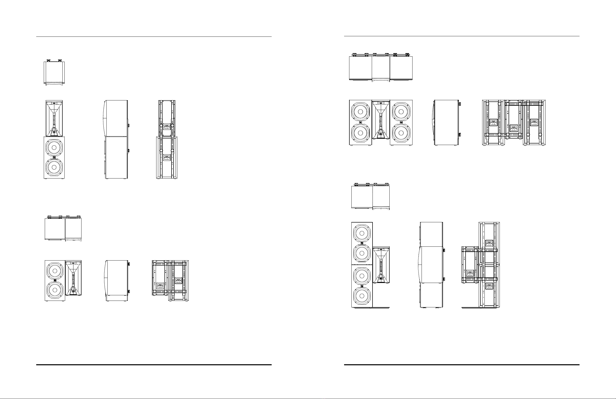
LEFT AND RIGHT SPEAKERS:If you have purchased a Synthesis Array
Module digital home theater system, then one of the configurations of the
SAM1HF/SAM2LF modules will serve as your front left and right main
speakers. Please see the Configuration and Connection diagrams in the
“SAM1HF and SAM2LF Configuration and Assembly” section to
correctly configure your main speakers.
Since the left and right speakers have been designed for maximum local-
ization of sound, they should be placed with the center of the speakers at
about the same height on screen as the actors would be, to aid in the illu-
sion that the actors’ voices are coming directly from their on-screen images.
Ideally, the speakers will be placed about 45 degrees apart from each other,
viewed from the listening position, so that the distance between the speakers
is the same as each speaker’s distance from the listener (see Figure 1).
CENTER CHANNEL SPEAKERS:Please see the Configuration and
Connection diagrams in the “SAM1HF and SAM2LF Configuration and
Assembly” section to correctly configure your center speaker. Regardless
of the configuration you have chosen, it is important to place the horn
array vertically during installation in order to take advantage of its sound-
dispersion characteristics. If you mount it horizontally, it will not provide the
correct dispersion pattern. If the speaker is being used with a perforated
projection screen, it should be mounted behind the center of the screen
(see Figure 2).
If a nonperforated projection screen, plasma display or other fixed video
device is being used in the installation, then the recommended location is
directly below (and as close as possible to) the video display (see Figure 3),
although the inverse of this method will work also.
4
RCL
VIEWING
POSITION
FLOOR PLAN
Figure 1. 5.1-Channel system
Figure 2.
Figure 3.
SPEAKER PLACEMENT
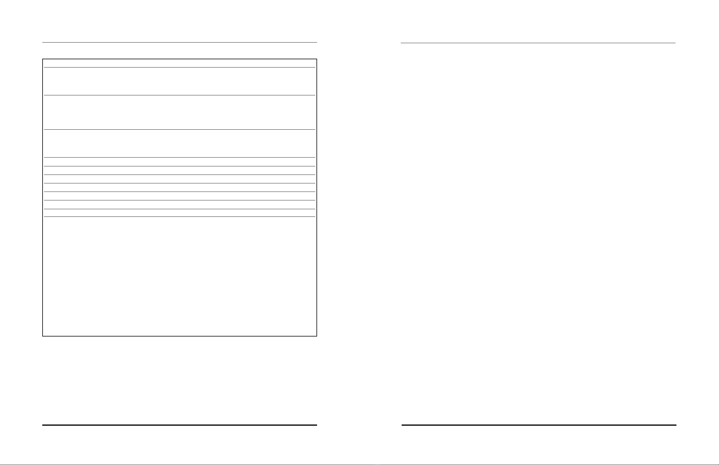
INCLUDED
SAM1HF
(2) mounting brackets: metal brackets for mounting to the SAM2LF module
(4) knobs: used to securely hold the mounting brackets to the cabinet
SAM2LF
(2) mounting brackets: metal brackets for mounting to the SAM1HF module
(4) knobs: used to securely hold the mounting brackets to the cabinet