JBL VERTEC DrivePack DP Series Manual

JBL VERTEC®DP Series
DrivePack™DP3–DPIP
Operator’s Guide

2

3
JBL VERTEC®DP Series DrivePack™ DP3–DPIP Operator’s Guide
Important Safety Instructions
1. Read these instructions.
2. Keep these instructions.
3. Heed all warnings.
4. Follow all instructions.
5. Do not use this apparatus near water.
6. Clean only with dry cloth.
7. Do not block any ventilation openings. Install in accordance with the manufacturer’s
instructions.
8. Do not install near any heat sources such as radiators, heat registers, stoves, or other
apparatus (including amplifiers) that produce heat.
9. Do not defeat the safety purpose of the polarized or grounding-type plug. A polarized
plug has two blades with one wider than the other. A grounding-type plug has two
blades and a third grounding prong. The wide blade or the third prong are provided for
your safety. If the provided plug does not fit into your outlet, consult an electrician for
replacement of the obsolete outlet.
10. Protect the power cord from being walked on or pinched, particularly at plugs,
convenience receptacles, and the point where they exit from the apparatus.
11. Only use attachments/accessories specified by the manufacturer.
12. Use only with the cart, stand, tripod, bracket, or table specified by the manufacturer,
or sold with the apparatus. When a cart is used, use caution when moving the
cart/apparatus combination to avoid injury from tip-over.
13. Unplug this apparatus during lightning storms or when unused for long periods of
time.
14. Refer all servicing to qualified service personnel. Servicing is required when the
apparatus has been damaged in any way, such as power supply cord or plug is
damaged, liquid has been spilled or objects have fallen into the apparatus, the
apparatus has been exposed to rain or moisture, does not operate normally, or has
been dropped.
15. WARNING: To reduce the risk of fire or electric shock, do not expose this apparatus to
rain or moisture.
16. Do not expose this equipment to dripping or splashing and ensure that no objects
filled with liquids, such as vases, are placed on the equipment.
17. To completely disconnect this apparatus from the AC Mains, disconnect the power
supply cord plug from the AC receptacle.
18. The mains plug of the power supply cord shall remain readily operable.

4
THIS APPARATUS CONTAINS POTENTIALLY LETHAL VOLTAGES. TO PREVENT ELECTRIC
SHOCK OR HAZARD, DO NOT REMOVE DRIVEPACK CHASSIS, INPUT MODULE OR AC
INPUT COVERS. NO USER SERVICEABLE PARTS INSIDE. REFER SERVICING TO QUALIFIED
SERVICE PERSONNEL.
WATCH FOR THESE SYMBOLS
The lightning bolt triangle is used to alert the user to the risk of electric shock.
The exclamation point triangle is used to alert the user to important operating or
maintenance instructions.
FCC COMPLIANCE NOTICE
This device complies with part 15 of the FCC rules. Operation is subject to the following two
conditions: (1) This device may not cause harmful interference, and (2) this device must accept any
interference received, including interference that may cause undesired operation.
CAUTION: Changes or modifications not expressly approved by the party responsible for compliance
could void the user’s authority to operate the equipment.
CSA COMPLIANCE NOTICE
CSA Certification Applies to Amplifier Module Only

5
Declaration of Conformity
Safety and EMC Compliance Specifications
EN 55103-1:1997 Electromagnetic Compatibility - Product Family Standard for Audio, Video,
Audio-Visual and Entertainment Lighting control Apparatus for Professional Use, Part 1:
Emissions
EN 55103-1:1997 Magnetic Field Emissions-Annex A @ 10 cm and 1 M
EN 55022:2003 Limits and Methods of measurement of Radio Disturbance Characteristics of
ITE: Radiated, Class B Limits; Conducted, Class A
EN 55103-2:1997 Electromagnetic Compatibility - Product Family Standard for Audio, Video,
Audio-Visual and Entertainment Lighting Control Apparatus for Professional Use, Part 2:
Immunity
EN 61000-4-2:1995 + A1:1999 & A2:2001 Electrostatic Discharge Immunity (Environment E2-
criteria B, 4 kV Contact, 8 kV Air discharge)
EN 61000-4-3:2003 Radiated, Radio-frequency, Electromagnetic Immunity (Environment E2,
criteria A)
EN61000-4-4:2005 Electrical Fast Transient/burst Immunity (criteria B)
EN 61000-4-5:2001 Surge Immunity (criteria B)
EN 61000-4-6:1996 Immunity to Conducted Disturbances Induced by Radio-Frequency Fields
(criteria A)
EN 61000-4-11:2004 Voltage Dips, Short Interruptions and Voltage Variation
UL 60065:2003, 7th edition: Audio/Video and musical instrument apparatus for household,
commercial and similar general use.
IEC 60065, 2001: Audio, Video and similar electronic apparatus - safety requirements
CAN/CSA E60065-03: Audio, video and similar electronic apparatus – Safety requirements.

6
Introduction to the JBL VERTEC®DP Series Integrated Audio System
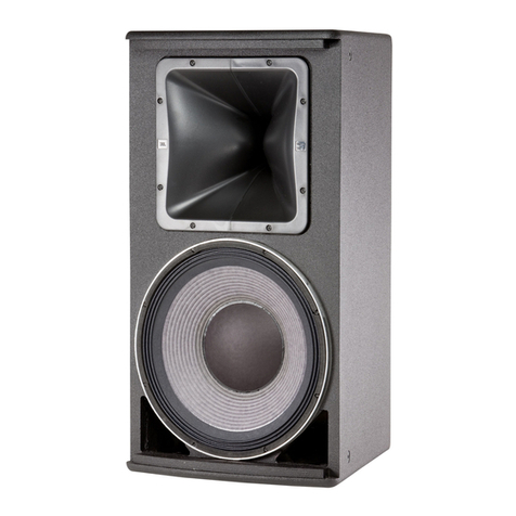
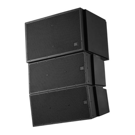
The JBL VERTEC®DP Series is a family of fully integrated audio systems, coupling industry-leading loudspeaker technology
to the innovative JBL DrivePack™ technology platform: a combination of comprehensive digital signal processing and
advanced amplifier technology, perfectly matched to the enclosures to deliver superb audio quality and powerful
performance.
The DrivePack is attached to the back of each VERTEC®DP Series enclosure, creating a seamless electro-mechanical system
that offers both convenience and portability along with the unmatched reliability, accuracy and superb sound of JBL
loudspeakers. The DrivePack includes onboard DSP functionality to communicate readiness and operational status,
including a self-test cycle and lighted indicators for fault detection upon power-up.
JBL DrivePack™ Signal-Processing & Amplification Unit
The JBL DrivePack™ electronics unit is intended to be used when mounted to a speaker enclosure of ⅝"
minimum thickness of wood or composite material and with load impedances of 4, 8, or 16 Ohms for low and
mid frequency channels, and 8 or 16 Ohms for the high frequency channel.
Package Contents
• Operator’s Guide (this document)
• VT48XXDP loudspeaker
• AC Power North America/Europe Cord-Set
• Protective Jacket Set
• JBL Warranty Card
QUICK-START OPERATING INSTRUCTIONS
All that is required to get your VERTEC®DP Series system up and running is to connect an AC power source to the AC
Power module via the Neutrik PowerCon™ inlet connector, and a full range line level audio signal to the Input module via
the AUDIO IN XLR connector.
Upon initial power-up of the DrivePack, the Blue Power LED will illuminate and the Green DP Ready indicator (located to
the left of the input module input level control) will flash during the boot-up and AC line auto-select soft-start process. The
DrivePack is equipped with Auto-Sensing Universal AC Voltage Selection and can operate anywhere in the world that has
an available 100-120VAC or 200-240VAC power source. On the power-up sequence the DPIP senses line voltage and sets
the high voltage line select relay within about two seconds. The system is ready for operation when the Green Ready LED
on both the AC Input module and the DPIP module is steadily illuminated.

7
Controls, Indicators and Connectors
See Figure 1
CONTROLS
1) Subwoofer Filter Enable Select Switch
a) Momentary, Enables or disables the selected function.
On subwoofer applications the low-pass frequency is set
to 80 Hz and for full range systems the high-pass is
raised to 80 Hz. (Slopes & knee shapes are model
dependent.)
6) Input Sensitivity/Attenuation Control:
a) 16 dB Precision Detented rotary control, 0.5 dB steps.
Sensitivity +4 dBu nominal (+23 dBu clip) with the
control fully counter clockwise, and -10 dBV nominal
(+4 dBV clip) with the control fully clockwise.
INDICATORS
2) SUBWOOFER FILTER ENABLE
a) Orange LED, illuminates when the function is enabled
3) FAULT
a) Red LED, illuminates during any fault condition
4) READY
a) Green LED, illuminates when the system is ready for operation
5) THERMAL Protection
a) Orange LED, illuminates during thermal limiting and protection:
iii. PULSING indicates first stage of thermal limiting, amplifier output level is reduced to prevent overheating.
iii. FLASHING indicates transducer thermal limits have been exceeded. Further reduction in output level is applied.
iii. SOLID illumination indicates thermal protection is in the second stage of protection and amplifier shut down
may occur if immediate action is not taken to correct the external reason for excessive heating of the amplifier.
7) SIGNAL/CLIP
a) (Signal) Green LED, detects input signal above the threshold set at –70 dBu.
b) Yellow indicates that the audio drive signal has exceeded limits preset in DSP on any channel and
compression/limiting is active.
7) c) (Clip) Red LED, Clip detection monitors input, DSP, and each amplifier output channel. The LED changes from
Green to Red when clipping THD at any point is detected.
INPUT CONNECTORS
8) AUDIO IN
a) F-XLR Active 20 KOhm Balanced, 10 KOhm Unbalanced
b) Pin 2 Hot (Positive voltage produces outward cone motion of L.F. transducers)
9) AUDIO OUT
a) M-XLR Passive Audio Pass-through
b) Pin 2 Hot (Positive voltage produces outward cone motion of L.F. Transducers)
AUDIO DISTRIBUTION
Connecting source audio signals to VERTEC®DP systems is similar to daisy-chaining multiple external amplifier channels
together. Assuming an output device source impedance of 100 Ohms and a 10:1 load to source ratio, 20 VERTEC®DP units
can typically be linked together on one output source without using a distribution amp.
1
3
4
5
6
7
2
8
9
Figure 1

8
AC POWER REQUIREMENTS
VERTEC®DP Series line array elements are equipped with a DP multi-channel Crown Class-I power amplifier and dbx™
loudspeaker specific DSP electronics and require appropriate AC power.
CAUTION: In compliance with safety agency criteria and proper system operation, it is critical that the system
installer observe all electrical safety practices at all times and provide proper earth grounding for
all AC Power connections.
AC Power Cord-sets
Convenience 120VAC North America NEMA 5-15 Edison type AC plug to PowerCon®connector and 240V Europe CEE 7/7
Schuko type AC plug to PowerCon®connector cord sets are provided with this VERTEC®DP Series product for light-duty
shop testing or system configuration type use.
One spare gray Neutrik (P/N NAC3FCB) PowerCon®connector is included in the AC Power Cord Set for your convenience
to create a pass-through AC power cable. To create a pass-through cable the system installer may choose to simply cut off
the AC plug from one of the provided AC cord sets and replace it with the provided Gray PowerCon®AC Outlet
connector. Follow the wiring convention indicated in Table 1.
NOTE: Fasten bushing by means of a fork wrench 3/4 min. Torque 2.5Nm (1.8lb-ft) to prevent opening by hand.
USER FABRICATED AC POWER DISTRIBUTION
System owners may choose to fabricate or purchase a custom AC Power cable infrastructure optimized for their specific
VERTEC®DP line array system configuration. See Table 1 for custom application wiring and connector information.
NOTE: Parts not provided.
CAUTION: Do not exceed 80% current rating of any AC connector at any time!
See Table 2 for current draw information.
Table 1
User Fabricated AC Cable and Connector Information
AC Inlet Cable Connector Neutrik PowerCon®NAC3FCA quick lock 3-pole A-type cable connector for power inlet.
Rated current per contact: 20 A (rms), Rated Voltage: 250VAC
AC Outlet Cable Connector Neutrik PowerCon®NAC3FCB quick lock 3-pole B-type cable connector for power
outlet. Rated current per contact: 20 A (rms), Rated Voltage: 250VAC
Wiring Cable: screw-type terminals or soldering nom. wire size/contact: 2.5 mm2/ 14 AWG
Wiring convention Ground –Ground, Neutral – Neutral, AC Hot – AC Hot
With the two non-interchangeable types of connectors (A-type, B-type) it is impossible to produce a short circuit. Mating
connectors (combination) are identified by mechanical keyways and by color.
Power Connector Coding
A-type (POWER INLET); Cable connector: Blue
B-type (POWER OUTLET) Cable connector: Gray, with Blue bushing
Table 2
DP3 AC Power Ratings
Description 120VAC 240VAC
Idle (Sleep Mode) <35W
Quiescent Power Draw <120W
1/8th power pink noise (UL/CSA) 600W, 5A rms 600W, 3.3A rms
1/3rd Power, Pink Noise 10.5 A 5.25 A
Maxiumum Power Draw 4500W
Inrush Current Inrush current limiting via PTC soft-start
AC Power Module Connectors: 12A Max, 100-120VAC/220-240VAC, 50-60 Hz. Class 1 Wiring 16 AWG (1.5 mm2)
Inlet Connector Rating 5A 3.3A w/16 AWG (1.5 mm2)
Outlet Connector Rating 7A 9A wiring
9
Line Voltage Selection: The DrivePack features an international Auto-Sensing power supply and will automatically select
the correct operating voltage range window. Automatic voltage selection is between 100-120VAC and 200-240VAC
operation, 50/60Hz.
Line Voltage Tolerance: The amp will operate normally (with expected de-rating in power output during low line
conditions) over a range of 100-120VAC +/-10% or 200-240VAC +/-10% AC input voltage. The amp will shut down for
voltages below nominal line and self protect for over-voltage beyond 15% nominal line.
CAUTION: Continuous voltages 10% beyond high line at either 120VAC or 240VAC operation ranges can
disrupt performance of the DrivePack™! To avoid activation of amplifier low line/high line protection which
will interrupt audio performance, the system operator should maintain AC supply voltages within the rated
voltage windows.
AC POWER MODULE
POWER Indicator:
Blue LED – located near power inlet lights when AC power
applied
Amp READY Indicator:
Green LED near power inlet, on during normal operation.
Long pulse during sleep mode.
Sleep Mode:
If audio input signals are not detected for 2 hours, the
amplifier will go into sleep/standby mode; the amplifier
output section is turned off while the supply powering the
DPIP Input Module and DSP logic remains active. This
mode reduces current draw and heat loss. While in sleep
mode the READY indicator pulses slowly. Recovery from
sleep mode is instantaneous when an audio signal is
detected.
THERMAL MANAGEMENT: VERTEC®DP Series systems are cooled by Passive Convection. No fans are used in any part of
the thermal management system. To maintain efficient cooling it is a good practice to to assure open space around the
DrivePack units.
Operating Temperature: The system will remain touchable during quiescent operation and will not provide a burn
hazard during any operating condition.

10
PROTECTIVE JACKET INSTALLATION
Complies with IEC 60529 - IPX-3, not evaluated for outdoor use
1. Remove two protective jackets from the protective jacket kit.
To install, open the jacket by “unzipping” the Velcro strip and
locate two smaller Velcro tabs on the inside of the jacket. See
Figure 2
2. Open the center Velcro tab and insert through the opening in
the module riser. See Figure 3
3. Next, wrap the left side of the cover around the bottom edge
of the riser. Insure that the bottom of the jacket is tucked into
the riser ring crevice between the top of the chassis and the
bottom of the riser ring rim. See Figure 4.
4. Pull the second Velcro tab through the second opening in the
riser ring. See Figure 4
Figure 3
Figure 4
Figure 2

11
5. Wrap the opposite end of the open jacket around the riser
ring as shown in Figure 5. Be certain that the bottom of the
protective jacket is tucked-in all the way around the riser ring
as shown.
6. “Zip” up the Velcro strip and pull the draw cord closed as
required as shown in Figure 6. The protective jacket should
now be securely fastened all the way around the riser ring at
the bottom and top end of the jacket and should be closed
securely forming a protective closure around the connector
panel.
7. Repeat the process for the other connector panel.
NOTE: Once attached, it is recommended the Protective Jackets be stored inside the molded assemblies at each end of the
DP3. Note that each end-cap has a storage space inside, and can accommodate a jacket once the Velcro strip has been
"unzipped" and the jacket has been unwrapped from the module riser (trim piece).
To implement this procedure, unhook the second short Velcro tab (shown being attached in Figure 4) from the slotted
opening in the riser. Do not dis-connect the first short Velcro tab (which was affixed as shown in Figure 2).
Stuff the jacket into the storage space inside the end-cap. To ensure retention of the jacket during storage in this space, be
sure to keep the first Velcro tab (closest to the end of the DrivePack unit) firmly attached through the slot. For ease of
removal from the storage space in the end-cap, orient the elastic drawstring towards the top of the compressed jacket, as it
resides in the end-cap. Pulling on the drawstring will then un-compress the stored jacket, and reveal it for re-installation
on the riser when required.
Figure 6
Figure 5

JBL Professional
8500 Balboa Boulevard, P.O. Box 2200
Northridge, California 91329 U.S.A.
© Copyright 2005 JBL Professional
A Harman International Company
360850-002
CRP
04/05
VERTEC®DP SERIES SYSTEM SUPPORT
Mailing Address:
JBL Professional
8500 Balboa Blvd.
Northridge, CA 91329 USA
Shipping Address:
JBL Professional
8370 Balboa Blvd., Dock D
Northridge, CA 91329 USA
(Do not return product to this address without first
obtaining prior authorization from JBL)
Customer Service:
Monday through Friday
8:00am - 5:00pm
Pacific Coast Time In the U.S.A.
(800) 8JBLPRO (800.852.5776)
www.jblproservice.com
On the World Wide Web:
www.jblpro.com
Outside the USA:
Contact the JBL Professional Distributor in your area. A
complete list of JBL Professional international distributors is
provided at our U.S.A. website - www.jblpro.com
Product Registration:
Register your product online at www.jblpro.com/registration
WEBLINKS
JBL PROFESSIONAL: WWW.JBLPRO.COM
VERTEC®PRODUCTS: WWW.JBLPRO.COM/VERTEC1/NEW_VERTEC/
JBL CUSTOMER SERVICE: WWW.JBLPROSERVICE.COM/
VERTEC®EMAIL ADDRESS: [email protected]
This manual suits for next models
1
Table of contents
Other JBL Stereo System manuals

JBL
JBL Authentics L 16 User manual

JBL
JBL Soundgear SG2020 User manual

JBL
JBL L75ms User manual

JBL
JBL ProPerformers Plus User manual

JBL
JBL Soundzone SMS1 User manual

JBL
JBL L75ms User manual

JBL
JBL PARTYBOX Encore Essential User manual

JBL
JBL EON15 G2 User manual

JBL
JBL EON 208p User manual

JBL
JBL Soundzone SMS1 User manual

JBL
JBL JBL3310 User manual

JBL
JBL CINEMA PROPACK 600 II User manual

JBL
JBL spyro User manual

JBL
JBL Performance AV1 User manual

JBL
JBL VLA-C SERIES User manual

JBL
JBL CINEMA PROPACK 600 II User manual

JBL
JBL CINEMA SB150 User manual

JBL
JBL Authentics L8 User manual

JBL
JBL Spot User manual

JBL
JBL Authentics L8 User manual