JCHADWICK 8400K User manual

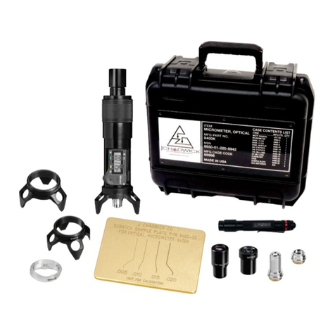
8400K: Kit Contents
Standard Items:
P/N Item Description
18400-0 Optical Micrometer
(shown with eyepiece, objective and base installed)
28400-7 Base, 3-Leg
38400-8 Base, 4-Leg
48400-91 Base, Clear Acrylic V-Block
58400-14 Eyepiece, 20X
68400-15 Eyepiece, 10X w/ Reticle Scale
78400-16 Objective Lens, 10X
88400-17 Objective Lens, 4X
98400-23 LED Flashlight w/ Adapter Tip
10 8400-25 Case
11 8400-32 Scratch Sample Plate
Optional Items:
P/N Item Description
8400-12 Base, 3-Leg Offset
8400-7-1 Base, 3-Leg, Delrin Tip
8400-27 Base, 3-Leg, Large
8400-35 Base, 2-Leg
The 11 piece kit includes
interchangeable optics
and bases for different
applications and a
Scratch Sample Plate for
training. The entire kit ts
in a portable case and
weighs less than 7 lbs.
1
7
11
4
3
2
5
6
8
9
10
Eyepiece
Focus Adjustment
Digital Display
Base
Objective Lens
Flashlight Receptacle
Model 8400 Optical Micrometer
1

Interchangeable Parts
The eyepiece can be removed
by grasping with thumb and
forenger and sliding in or out
of the eyepiece sleeve. Care
should be taken to avoid dirt
or moisture entering the tube
when removing eyepiece.
A 10X reticle eyepiece enables
visual width measurements.
Width observations are valid
only at 100X magnication
(10X Reticle Eyepiece with
10X Objective Lens).
To change the objective lens,
turn the focus adjustment
clockwise until the threads of
the objective lens are visible
at the base of the Micrometer.
Holding the Micrometer body
rmly, grasp objective lens and
turn counter-clockwise until
threads disengage.
100X and 200X magnication
is recommended for inspecting
scratch depth, scribe lines,
blind holes, corrosion pits,
spurs and other very small
protrusions or indentations.
40X and 80X magnication is
recommended for inspecting
transparent materials for
overall thickness and the depth
of fractures and imbedded
bubbles or “seeds”.
Both the eyepiece and the
objective lens can be
removed and replaced for
levels of magnication from
40X to 200X. Bases can be
swapped to accommodate
different surfaces.
To remove a base, rmly hold
the Micrometer barrel and turn
the base counter-clockwise
until the threads disengage.
To replace, select desired base
and thread onto the Micrometer
body in a clockwise direction.
DO NOT OVER-TIGHTEN.
The tripod base is
recommended for at surfaces.
The quadpod base is
recommended for simple
curved surfaces.
The transparent V-block base
is recommended for small
diameters, outside angles and
at surfaces near a recess.
Four additional bases are
available, please call for price
and availability.
▪An offset base for
measurements along edges.
▪A delrin-tipped tripod base
for delicate nishes.
▪A large tripod base for parts
inspection.
▪A wedge bipod base for
corners and inside angles.

Operation: Taking Measurements
The Micrometer features a very shallow depth
of focus that allows the distance between
two points at different depths to be easily
measured. Areas within the focal plane will
appear sharp while areas above and below
this plane will be out of focus.
The Micrometer does not feature prismatic
correction, so the image is inverted.
▪ Step 1
Shine ashlight
through the eyepiece
to create a pin-point
spot. Use spot to
position Micrometer
directly over region of
interest (ROI).
▪ Step 2
Without moving the
Micrometer, place lit
ashlight in desired
ashlight receptacle
on base.
▪ Step 5
Focus into the bottom of damaged area (“Surface
B” in diagram below).
▪ Step 6
Record depth shown on digital display.
▪ Step 7
This step is for verication only. Re-focus on
the top surface, display should show “0.0000”.
▪ Step 8
Repeat steps 3-7 for verication.
Transparencies
For transparent materials it is necessary to know
the refraction index of the specic material. The
Micrometer reading must be multiplied by the
refraction index for an accurate result.
For instance, if measuring the overall thickness
of a plexiglass window and the Micrometer reads
0.3600”, the actual thickness of the window is
0.3600 x 1.49 (the refractive index of plexiglass),
or 0.5364”.
Bubbles inside transparent materials are air
space and not subject to the refraction index.
Hold the base of micrometer for support while
focusing to prevent it from moving.
▪ Step 3
Look through the eyepiece and use
the focus adjustment to bring the
primary surface (the undamaged
surface directly next to the scratch or
pit, “Surface A” in diagram at right)
into sharp focus.
At 100X magnication, the
objective lens will be approximately
1/4” over the target when in focus.
▪ Step 4
Press the “ZERO/ABS” button
(display should now read “0.0000”).

Specications Calibration
▪DIMENSIONS & WEIGHT
8400K KIT IN CASE
16” x 7” x 5”, 5 LBS
8400-0 MICROMETER ONLY
9” HEIGHT, 2” DIA STEM, 3” DIA BASE,1.5 LBS
▪ACCURACY & RESOLUTION
In inches, the digital readout shows 4 decimal
places; “0.0000”. The far right (ten-thousandths)
rounds-off and reads “0” or “5” (0.0000 or
0.0005).
In millimeters, the readout shows 2 decimal
places; “0.00”. The far right (hundredth-mm)
place reads in 0.01 mm increments.
ACCURACY +/- 0.001” / 0.02mm
RESOLUTION 0.0005” / 0.01 mm
▪RANGE
10X OBJECTIVE LENS
Vertical range (or depth) 0.250” (6.4mm) from
surface to bottom of scratch.
Width of 0.040” (0.02mm) can be visually
measured with the reticle eyepiece.
Width observations are valid only at 100X
magnication (10X Reticle Eyepiece with 10X
Objective Lens).
4X OBJECTIVE LENS
Vertical range (or depth) 1.250” (32mm)
from surface to bottom of scratch.
▪TEMPERATURES
OPERATING
0ºC to 40ºC / 32ºF to 140ºF
STORAGE
-10ºC to 60ºC / 14ºF to 140ºF
Recommended Calibration Cycle: 1 Year
A. EQUIPMENT
Gage blocks, calibrated and traceable to NIST.
Sizes: 0.0625, 0.1000”, 0.1250”, 0.2000”
B. INSTRUCTIONS
▪ Step 1
Wring 0.1000” and 0.0625” gage blocks together
by sliding one block across the top of another,
creating a step (see diagram below).
▪ Step 2
Place micrometer over the step created by the
two blocks. Position so approximately one half
of the eld of view is on the upper block. (See
diagram below.)
▪ Step 3
Focus on the surface of the upper block
(1in diagram below).
▪ Step 4
Set Zero “0.0000” on digital display.
▪ Step 5
Focus on lower block (2in diagram below).
▪ Step 6
Read display; if equipment is functioning properly
the display will show thickness of upper block.
▪ Step 7
Repeat steps 1-5, using the 0.1250” and 0.2000”
gage blocks.
Top View Side View
1
2
Field of View

Warranty
John Chadwick Corporation DBA J Chadwick Co
warrants the 8400K Digital Optical Micrometer
Kit, herein referred to as the product, against
defects in material or workmanship as follows;
LABOR
For a Period of two (2) years from the purchase
date, if the product is determined to be
defective, J Chadwick Co will repair the product
at no charge to the buyer. If the product is
determined by J Chadwick Co to be defective
beyond repair, a replacement will be provided.
PARTS
For a period of two (2) years from the date of
purchase, if the product or its components are
determined defective, J Chadwick Co will supply,
at no charge to buyer, new or rebuilt parts.
DISCLAIMER
(1) This warranty does not cover cosmetic
damage or damage due to acts of God, accident,
misuse, abuse, or negligence to any part of the
product.
(2) This warranty does not cover damage due to
improper operation or maintenance. Warranty is
null and void if repair or modication is attempt-
ed by anyone other than J Chadwick Co or its
authorized representatives.
Repair or replacement as provided under this
warranty is the exclusive remedy of the consumer.
J Chadwick Co shall not be liable for any inci-
dental or consequential damages for breach of
any express or implied warranty on the product.
To obtain warranty service, buyer must contact
J Chadwick Co prior to return to obtain an
authorization to return the product for service.
Buyer is responsible for providing proof of sale,
which may be required for warranty service. The
product should be returned to J Chadwick Co,
in either its original packaging or packaging
affording an equal degree of protection, with a
copy of the bill of sale.
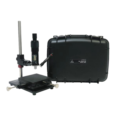
Increase the versatility of the Optical
Micrometer with these products. Please
call for more details and pricing.
A versatile addition designed for shop and lab
environments to inspect subjects requiring more
clearance and easier accessibility (such as large
or oddly shaped parts) than the Optical Micrometer
provides when used alone.
Lab Stand Kit
Model 5500
The Surface Replication Kit features Microset®
replicating compounds; the kit allows for a quick
and convenient method to obtain precise
measurements in hard-to reach places (such as the
inside of threaded holes).
Surface Replication Kit
Model 4400

Toll Free (866) 358-9955
Tel (626) 358-9955
Fax (626) 358-1448
www.jchadwickco.com
sales@jchadwickco.com
1005 S Mountain Ave. Monrovia CA 91016 USA
Table of contents
Other JCHADWICK Laboratory Equipment manuals
Popular Laboratory Equipment manuals by other brands

Heidolph
Heidolph Hei-TORQUE Core operating manual

VWR
VWR avantor EHP instruction manual

Emotiv
Emotiv EPOC quick start guide

CytoTherm
CytoTherm CytoTherm-4S owner's manual

Agilent Technologies
Agilent Technologies InfinityLab LC Series quick guide

QUANTIFOIL Instruments
QUANTIFOIL Instruments BioShake iQ quick start guide