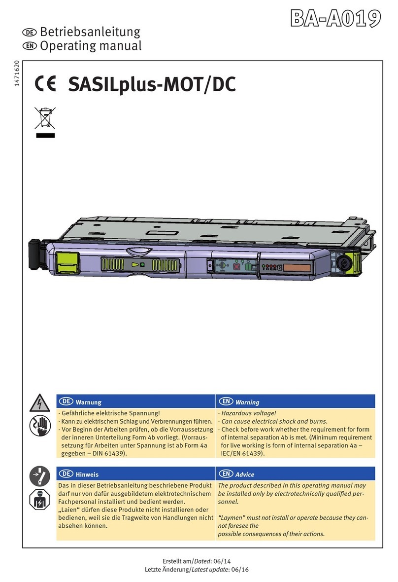
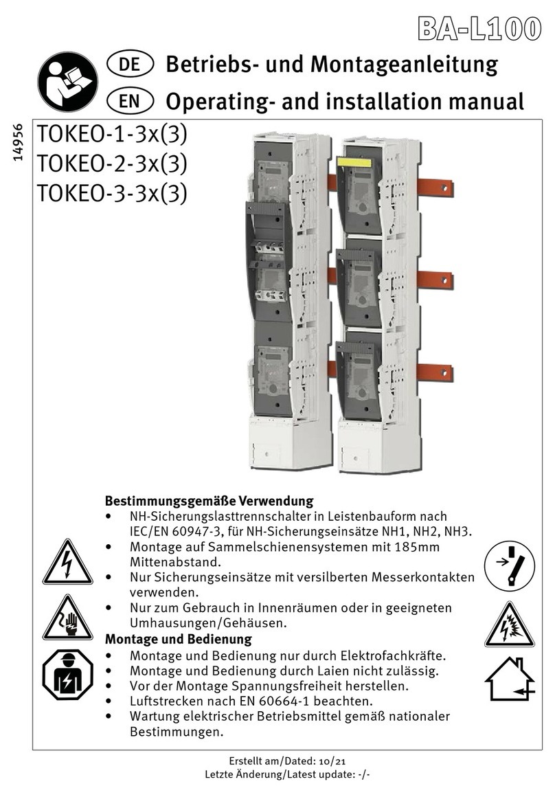
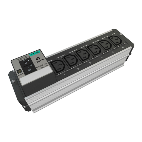
JEAN MÜLLER SASILplus BA-A025 User manual

Instrukcja obsługi
Operating manual
PL
EN
Notice d’installation
Gebruiksaanwijzing
FR
NL
SASILplus 185mm / 60mm podwójnie rozłączalny (NH + System BS)
SASILplus 185mm / 60mm double pluggable (NH + BS System)
SASILplus 185mm / 60mm double enfichable (NH + BS System)
SASILplus 185mm / 60mm dubbele pluggable (NH + BS System)
DE
EN
FR
NL
PL Uwaga
•Niebezpieczne napięcie elektryczne
•Może prowadzić do porażenia i oparzeń
•Przed rozpoczęciem prac należy upewnić się czy jest
zachowany warunek podziału wewnętrznego 4b
(wymagania dotyczące prac pod napięciem są
określone od formy podziału wewnętrznego 4a w
normie IEC/DIN EN 61439-2).
EN Warning
• Hazardous voltage!
• Can cause electrical shock and burns.
• Check before work whether the requirement for
form of internal separation 4b is met. (Minimum
requirement for live working is form of internal
separation 4a - IEC/EN 61439-2).
FR Avertissemant
Tension électrique dangereuse!
Ceci peut mener aux chocs et aux combustions
électriques.
Avant d‘effectuer des travaux vérifiez si les
exigences de la forme de séparation interne 4b
sont remplies.
(L‘exigence minime pour les travaux sous tension
est la forme de séparation interne 4a en respectant
les obligations légales locales – IEC/EN 61439-2).
NL Waarschuwing
Gevaarlijke elektrische spanning!
Dit kan leiden tot elektrische schokken en
verbrandingen.
Zorg voor het begin van de werkzaamheden dat
aan de eisen van interne scheiding volgens
bouwvorm 4b is voldaan.
(De minimale eis voor het werken onder spanning
is de interne scheiding volgens bouwvorm 4a en
volgens de plaatselijk geldende voorschriften –
IEC/EN 61439-2)
14889
Erstellt am/Dated: 03/18
Ostatnia aktualizacja/Latest update: 01/22

14889
2 / 22
PL Wskazówka
Opisany w poniższej instrukcji montażowej
produkt może być obsługiwany tylko przez osoby
przeszkolone i uprawnione.
"Laicy" nie powinni pod żadnym pozorem
obsługiwać i instalować tych urządzeń ponieważ
nie są w stanie przewidzieć konsekwencji tego
postępowania.
EN Advice
The product described in this operating manual
may be installed only by electrotechnically
qualified personnel.
“Laymen” must not install or operate because they
cannot foresee the possible consequences of their
actions.
FR Remarque
Le produit décrit dans cette notice d’installation ne
peut être installé et commuté que par un électricien
qualifié.
«Non-initiés» ne peuvent pas installer ou utiliser
ces produits parce qu’ils ne peuvent pas prévoir
les conséquences de leurs actes.
NL Aanmijzing
Het in deze montage instructie beschreven produkt
mag alleen door geschoold elektrotechnisch
vakpersoneel worden geinstalleerd en bediend.
“Leken” mogen deze produkten niet installeren of
bedienen, omdat zij de consequenties niet overzien
kunnen.
PL EN FR NL
Właściwe użytkowanie / Intended Use Utilisation
conforme / Begoogd gebruik
Opisany w poniższej instrukcji montażowej produkt jest przeznaczony do zabudowy w odpowiednich rozdzielnicach
nn, celem zabezpieczenie obwodów prądowych wkładkami typu NH i BS zgodnie z obowiązującymi normami
DIN VDE 0636-2 i BS88-2
The product described in these operating instructions is intended for installation in suitable housings and for moun-
ting NH/BS fuse links according to DIN VDE 0636-2 or BS88-2 for the protection of electrical circuits.
Le produit décrit dans ce mode d'emploi est prévu pour le montage dans des boîtiers appropriés et pour le monta-
ge de fusibles NH/BS selon DIN VDE 0636-2 ou BS88-2 pour la protection des circuits électriques.
Het in deze technische handleiding beschreven product is bestemd voor de inbouw in geschikte behuizingen en
voor de montage van NH/BS-zekeringsschakelaars volgens DIN VDE 0636-2 of BS88-2 voor de beveiliging van
elektrische circuits..
EN
NL
PL
FR
PL EN FR NL
Zabezpieczenie kłódką / Locking capability with padlock
Verrouillable au moyen de cadenas / Vergrendelbaar d.m.v. hangslot
Do zabezpieczenia rozłącznika nadaje się kłódka o średnicy 5,7- 6,8mm
It is required to use a padlock with a shackle diameter of 5,7- 6,8mm.
L’utilisation d’un cadenas avec un diamètre de manille de 5,7- 6,8mm est
recommandé.
Een hangslot is met een beugeldiameter van 5,7- 6,8mm te gebruiken.
EN
NL
PL
FR

14889
3 / 22
PL EN FR NL
Wysokość modułów / Module height / Hauteur UF / Moduulhoogtes
Uwaga !
Używać bezpieczników tylko ze srebrzonymi nożami.
Attention !
Use fuse-links with silver-plated terminal blades only.
Avertissement !
Utiliser uniquement des fusibles à couteaux ou barrettes de neutre argentées.
Waarschuwing !
Uitsluitend smeltveiligheden met verzilverde messen of verzilverde
scheidingsmessen gebruiken.
EN
NL
PL
FR
SASIL-P.00/H../DS NH00 160 50 100
SASIL-P.2/H../DS NH2 400 150 300
SASIL-P.1/H../DS NH1 250 75 150
SASIL-P.3/H../DS NH3 630 150 300
Wysokość modułu
4-bieg. Modul height
4-pole Hauteur
tétrapolaire
Moduulhoogte
4-polig [mm]
Wysokość modułu
3-bieg. Modul height
3-pole Hauteur
tripolaire
Moduulhoogte
3-polig [mm]
Ilustracje/
Illustration/
Afbeeldingen
Wielkość/Size/
Taille/Grootte
Ie
[A]
NH
SASIL-P.BSA3/H../DS BS-A3 63 50 100
SASIL-P.BSB1/H../DS BS-B1 100 75 150
SASIL-P.BSBX/H../DS BS-BX 125 50 100
SASIL-P.BSB2/H../DS BS-B2 200 75 150
SASIL-P.BSB4/H../DS BS-B4 400 150 300
SASIL-P.BSB6/H../DS BS-B6 630 150 300
BS88

14889
4 / 22
PL EN FR NL
Obsługa / Handling / Commande / Bediening
(1) Załączanie (pokrywa musi być zablokowana) /Switch on (the door must be locked)
Enclencher (couvercle doit être fermé)/Inschakelen (schakeldeksel moet gesloten zijn)
(2) Rozłączanie (pokrywa musi być zablokowana)/Switch off (the door must be locked)
Déclencher (couvercle doit être fermé)/Uitschakelen (schakeldeksel moet gesloten zijn)
0201
0403
0201
0403

14889
5 / 22
PL EN FR NL
Pokrywa/ Door / Couvercle à charnières / Schakeldeksel
(3) Otwieranie / Open / Ouvrir / Openen
(4) Demontaż / Dismounting / Démontage / Demontage
0201
0201

14889
6 / 22
PL EN FR NL
Pokrywa / Door / Couvercle à charnières / Schakeldeksel
(6) Zamknięcie / Close / Fermer / Sluiten
(5) Montaż / Mounting / Montage / Montage
Wymiana pokrywy możliwa tylko w pozycji 20° a30° .
Change of strip cover only in the position 20° to 30°.
Alternance de bandes de couverture que dans la position 20° à 30°.
Wisselen, uitnemen van schakeldeksel (alleen met een hoek van 20° tot 30° mogelijk).
0201
0201
PL EN FR NL
Serwis/Maintenance instructions/Onderhoudsvoorschriften/Instructions d’entretien
PL
Przy zachowaniu "normalnych warunków pracy",
zgodnie z IEC/DIN EN 61439-1 rozłączniki SASILplus
spełniają wszystkie wymagania zawarte w normie
IEC/DIN EN 60947-3 i są bezobsługowe aż do
osiągnięcia przypisanych im cykli łączeniowych.
EN
In accordance with ”standard operating conditions“
regarding IEC/EN 61439-1 strips fulfill all prescribed
requirements regarding IEC/EN 60947-3 and are
maintenance free till reaching the declared switching
cycles.
FR
En conditions d’appliquer les «conditions normales
d’exploitation» selon la norme IEC/EN 61439-1 répond
jusqu’à atteindre le nombre des manoeuvres spécifi ées
sûrement à tous exigences selon la norme
IEC/EN 60947-3 et ne nécessite aucun entretien.
NL
Bij het naleven van de „normale bedrijfsomstandighe-
den“ volgens IEC/EN 61439-1 voldoet zeker tot het
bereiken van het opgegeven aantal schakelingen aan
alle voorgeschriften van de norm IEC/EN 60947-3 en
is onderhoudsvrij.

14889
7 / 22
PL EN FR NL
Wymiana wkładki bezpiecznikowej/Fuse replacement/Remplacement des fusibles/Vervangen
smeltpatronen
NH-System
Parametry bezpiecznika / Fuse data / Données fusibles / Gegevens smeltpatronen
Typ
Type Ie
[A]
400-690V gL/gG
Pv[W]
max.
Gwint /
thread /
filetage /
Schroefdraad
Moment
znamionowy /
tourquet /
moment de
rotation /
Aandraal
moment (Nm)
02
01
02
01
160 12
400 45
250 32
630
SASIL-P.00/H../DS NH00
SASIL-P.2/H../DS NH2
SASIL-P.1/H../DS NH1
SASIL-P.3/H../DS NH3 60
63 12
100 32
125 12
200 32
400 45
630
SASIL-P.BSA3/H../DS BS-A3
SASIL-P.BSB1/H../DS BS-B1
SASIL-P.BSBX/H../DS BS-BX
SASIL-P.BSB2/H../DS BS-B2
SASIL-P.BSB4/H../DS BS-B4
SASIL-P.BSB6/H../DS BS-B6
60
--
--
--
--
M5 2-4
M8 10-12
M8 10-12
M8 10-12
M8 10-12
M8 10-12
Pv = Max. dopuszczalne straty mocy na bezpieczniku
Max. permis. power loss per fuse-link
Perte de pulssnce admissible max. par fusible
Max. toelastbaarvvermogensverlies per zekering
le = Znamionowy prąd roboczy
Rated operational current
Courant assié d’emplol
Toegekende gebruiksstrom

14889
8 / 22
PL EN FR NL
Przyrząd do wkładania i wyciągania rozłącznika / Installation and removal tool /
Outil d'installation et de suppression / Installatie en verwijderingstool
zamawiany oddzielnie
included, must be ordered separately
inclus, doit être commandé séparément
Niet inbegrepen, moet apart worden besteld
Instrukcja montażu przy prowadnicy listwowej
Operating instructions for mounting strip guide
Mode d’emploi pour le strip guide des bandes de montage dans le domaine
Gebruiksaanwijzing voor montage van in de strokengeleiders
Art.Nr.:
A8500552 NH00
A8100552 NH1
A8700552 NH2-3

14889
9 / 22
System szyn w rozstawie 185mm / Example system 185mm /
Exemple systèm 185mm / Voorbeeld systeem 185mm
*Demontaż rozłącznika
Draw out of the unit
Débrochage d’une réglette
Uittrekken van de strook
PL EN FR NL
Montaż rozłącznika / Plug in the device / Enfi chage de la réglette / Inpluggen strook

14889
10 / 22
PL EN FR NL
Przyłącze kablowe: patrz instrukcja montażu / Cable connection: see installation instructions /
Raccordement du câble : voir instructions d'installation / Kabelaansluiting: zie montagehandleiding
Przyłącze kabli AGH
Wielkość: NH00 50/87.5/125mm
Przyłącze kabli AGH
Wielkość: NH1 50/87.5/125mm
Przyłącze kabli AGH
Wielkość: NH2-3 50/87.5/125mm
Instrukcja montażu
Instrukcja montażu
Instrukcja montażu
PL
PL PL
PL
PL
PL

14889
11 / 22
max. 1,5mm2
0,5 x 3mm
max. 0,4Nm
PL EN FR NL
Listwa wtykowa / Control circuit / Connecteurs à enfi chage 16-poles
pour déconnexion auxiliaire / 16-polige stekkerklem voor hulpbedrading

14889
12 / 22
3-bieg. NH00 / 3-pole NH00 / tripolaire / 3-polig NH00 185mm (DIN)
3-bieg. NH1 / 3-pole NH1 / tétrapolaire / 3-polig NH1 185mm (DIN)
PL EN FR NL
Wymiary / Dimensions / Dessins / Maatschetsen

14889
13 / 22
3-bieg. NH2-3 / 3-pole NH2-3 / tripolaire / 3-polig NH2-3 185mm (DIN)
PL EN FR NL
Wymiary/Dimensions/Dessins/Maatschetsen

14889
14 / 22
Wymiary pola do zabudowy na szynach w rozstawie, 185mm
Assembly dimension of the fi eld distribution device, 185mm busbar system
Dimensions d’assemblage de l’unité fonctionnelle (UF) dans système de jeux de barres 185mm
Inbouwafmetingen veldverdeelrailsysteem, 185mm railsysteem
PL EN FR NL
Wymiary/Dimensions/Dessins/Tekeningen

14889
15 / 22
Parametry
mechaniczne
Kenngrößen
Mechanical
characteristics
Rozstaw szyn zbiorczych
Busbar distance
-mm
-mm
-mm
-mm
Sammelschienendicke 3)
Busbar distance 3)
Stopień ochrony
Type of
protection
Od frontu aparat
zabudowany
Front side device
fitted
Stan pracy
Operational
state
Drzwi frontowe
otwarte
Front cover
open
185 (60) 9)
IP40
IP20
10 (5) 9)
Warunki
użytkowania
Operating
conditions
Temperatura otoczenia 2) 10)
Ambient temperature 2) 10)
Tu°C
--
Rodzaj pracy
Rated operating mode
-25 od/do +70
--
Sposób montażu
Mounting position
poziomo 4), pionowo 5)
Horizontal 4), vertical 5)
-m
Wysokość n.p.m.
Altitude above sea level Do/Up to 2000
--
Stopień zabrudzenia
Pollution degree
3
--
Kategoria przepięciowa
Overvoltage category
III
2) 35°C normalna temp. pracy, przy 70°C redukcja prądów roboczych
35°C normal temperature, at 70°C with reduced operating current
3) Szyna zbiorcza pionowa / Upright busbar
4) Przyłącze kablowe prawe, lewe / Cable connection right, left
Inne paramtery techniczne dostępne na stronie www.jeanmueller.de jak również w katalogu SASILplus
Further technical data you will find at our website www.jeanmueller.de or in our catalogue “SASILplus”.
5) Przyłącze kablowe dolne, górne / Cable connection bottom, top
9) Wartość odbiegająca dla SASILplus, rozstaw szyn 60mm
/Differing value for SASILplus, 60mm busbar system
10) ze zintegrowana elektroniką +55°C / at the electronics max + 55 °C
Praca ciągła / Continuous operation
NL
PL EN FR
Ogólne parametry techniczne / General Technical Data / données techniques générales /
algemene technische gegevens

14889
16 / 22
PL EN Parametry techniczne / Technical Data / données techniques / technische gegevens
3-bieg.,wielkość 00 i1 (185mm und 60mm Sammelschienensystem)
3-pole, size 00 and 1 (185mm and 60mm busbar system)
Parametry
elektryczne
Electrical
characteristics
Napięcie znamionowe pracy
Rated operational voltage
UeV
A
Prąd znamionowy
Rated operating current
AC400/
AC500
Hz
Częstotliwość znamionowa
Rated frequency
V
Znamionowe napięcie izolacji
Rated insulation voltage
AC1000
kV
Znamionowe napięcie udarowe
Rated impulse withstand voltage
8
W
Straty mocy przy Ith (bez wkładki bez.)
Total power loss at Ith (without fuse)
7) Odstęp od uziemionych części 0mm /
Distance to grounded parts 0mm
8) Wartość odbiegająca dla SASILplus, rozstaw szyn 60mm /
Differing value for SASILplus, 60mm busbar system
Typ
Type
SASIL-PL00/...31/...
SASIL-PL00/...36/...
SASIL-PL1/...31/...
SASIL-PL1/...36/...
AC400/
AC500
AC690
160 250
47 82
AC690
40-60
Ie
-
Ui
Uimp
Pv
Wysoka
zdolność
łączeniowa
High switching
capacity
Warunkowy znamionowy prąd zwarciowy 7)
Rated conditional shortcircuit current 7)
-kA
eff
AC-23B
Kategoria użytkowania
Utilization category
--
120 80
(65)8) 120 80
(65)8)
Inne paramtery techniczne dostępne na stronie www.jeanmueller.de jak również w katalogu SASILplus
Further technical data you will find at our website www.jeanmueller.de or in our catalogue “SASILplus”.
Trwałość łączeniowa elektryczna (cykle)
Operating cycles with current
200
Trwałość łączeniowa mechaniczna (cykle razem)
Operating life (total switching operations)
1600

14889
17 / 22
3-bieg., wielkość 2 i3 (rozstaw szyn zbiorczych 185mm i 60mm)
3-pole, size 2 and 3 (185mm and 60mm busbar system)
Parametry
elektryczne
Electrical
characteristics
Napięcie znamionowe pracy
Rated operational voltage
UeV
A
Prąd znamionowy
Rated operating current
AC400/
AC500
Hz
Częstotliwość znamionowa
Rated frequency
V
Znamionowe napięcie izolacji
Rated insulation voltage
AC1000
kV
Znamionowe napięcie udarowe
Rated impulse withstand voltage
8
W
Straty mocy przy Ith (bez wkładki bez.)
Total power loss at Ith (without fuse)
7) Odstęp od uziemionych części 0mm /
Distance to grounded parts 0mm
8) Wartość odbiegająca dla SASILplus, rozstaw szyn 60mm
/Differing value for SASILplus, 60mm busbar system
Typ
Type
SASIL-PL2/...31/...
SASIL-PL2/...36/...
SASIL-PL3/...31/...
SASIL-PL3/...36/...
AC400/
AC500
AC690
400 630
136 295
AC690
40-60
Ie
-
Ui
Uimp
Pv
Wysoka zdolność
łączeniowa
High switching
capacity
Wysoka zdolność
łączeniowa
High switching
capacity
Warunkowy znamionowy prąd zwarciowy 7)
Rated conditional shortcircuit current 7)
-kA
eff
AC-23B
Kategoria użytkowania
Utilization category
--
120 80
(65)8) 120 80
(65)8)
Inne paramtery techniczne dostępne na stronie www.jeanmueller.de jak również w katalogu SASILplus
Further technical data you will find at our website www.jeanmueller.de or in our catalogue “SASILplus”.
Trwałość łączeniowa elektryczna (cykle)
Operating cycles with current
200
Trwałość łączeniowa mechaniczna (cykle razem)
Operating life (total switching operations)
1000

14889
18 / 22
4-bieg., wielkość 00 i1 (rozstaw szyn zbiorczych 185mm)
4-pole, size 00 and 1 (185mm busbar system)
Parametry
elektryczne
Electrical
characteristics
Napięcie znamionowe pracy
Rated operational voltage
UeV
A
Prąd znamionowy
Rated operating current
AC400/
AC500
Hz
Częstotliwość znamionowa
Rated frequency
V
Znamionowe napięcie izolacji
Rated insulation voltage
AC1000
kV
Znamionowe napięcie udarowe
Rated impulse withstand voltage
8
W
Straty mocy przy Ith (bez wkładki bez.)
Total power loss at Ith (without fuse)
7) Odstęp od uziemionych części 0mm /
Distance to grounded parts 0mm
Typ
Type
SASIL-PL00/
...41/...
SASIL-PL1
/...41/...
AC400/
AC500
AC690
160 250
63 109
AC690
40-60
Ie
-
Ui
Uimp
Pv
Wysoka zdolność
łączeniowa
High switching
capacity
Warunkowy znamionowy prąd zwarciowy 7)
Rated conditional shortcircuit current 7)
-kA
eff
AC-23B
Kategoria użytkowania
Utilization category
--
100 100
Inne paramtery techniczne dostępne na stronie www.jeanmueller.de jak również w katalogu SASILplus
Further technical data you will find at our website www.jeanmueller.de or in our catalogue “SASILplus”.
65 65

14889
19 / 22
4-bieg., wielkość 2 i 3 (rozstaw szyn zbiorczych 185mm)
4-pole, size 2 and 3 (185mm busbar system)
Parametry
elektryczne
Electrical
characteristics
Napięcie znamionowe pracy
Rated operational voltage
UeV
A
Prąd znamionowy
Rated operating current
AC400/
AC500
Hz
Częstotliwość znamionowa
Rated frequency
V
Znamionowe napięcie izolacji
Rated insulation voltage
AC1000
kV
Znamionowe napięcie udarowe
Rated impulse withstand voltage
8
W
Straty mocy przy Ith (bez wkładki bez.)
Total power loss at Ith (without fuse)
7) Odstęp od uziemionych części 0mm /
Distance to grounded parts 0mm
Typ
Type
SASIL-PL00/
...41/...
SASIL-PL1
/...41/...
AC400/
AC500
AC690
400 630
181 392
AC690
40-60
Ie
-
Ui
Uimp
Pv
Wysoka zdolność
łączeniowa
High switching
capacity
Warunkowy znamionowy prąd zwarciowy 7)
Rated conditional shortcircuit current 7)
-kA
eff
AC-23B
Kategoria użytkowania
Utilization category
--
100 100
Inne paramtery techniczne dostępne na stronie www.jeanmueller.de jak również w katalogu SASILplus
Further technical data you will find at our website www.jeanmueller.de or in our catalogue “SASILplus”.
65 80

14889
20 / 22
2-bieg. (rozstaw szyn zbiorczych 370mm)
2-pole (370mm busbar system)
Parametry
elektryczne
Electrical
characteristics
Napięcie znamionowe pracy
Rated operational voltage
UeV
A
Prąd znamionowy
Rated operating current
V
Znamionowe napięcie izolacji
Rated insulation voltage
kAeff
Warunkowy znamionowy prąd zwarciowy 7)
Rated conditional shortcircuit current 7)
35
-
Kategoria użytkowania
Utilization category
W
Straty mocy przy Ith (bez wkładki bez.)
Total power loss at Ith (without fuse)
7) Odstęp od uziemionych części 0mm /
Distance to grounded parts 0mm
Typ
Type
SASIL-PL00/
H21/...
SASIL-PL1/
H21/...
DC440DC220 DC220
160 250
32 59
DC440
DC1000
Ie
Ui
-
-
Pv
Parametry
mechaniczne
Mechanical
characteristics
Rozstaw szyn zbiorczych
Busbar distance
-mm 370 (2 x 185)
Inne paramtery techniczne dostępne na stronie www.jeanmueller.de jak również w katalogu SASILplus
Further technical data you will find at our website www.jeanmueller.de or in our catalogue “SASILplus”.
DC-22B DC-22BDC-21B DC-21B
A
Znamionowa zdolność załączeniowa
Rated making capacity
-640 1000240 375
A
Znamionowa zdolność załączeniowa
Rated breaking capacity
-640 1000240 375
kV
Znamionowe napięcie udarowe
Rated impulse withstand voltage
Uimp 8
Trwałość łączeniowa elektryczna (cykle)
Operating cycles with current
200
Trwałość łączeniowa mechaniczna (cykle razem)
Operating life (total switching operations)
1600
Other JEAN MÜLLER Power Distribution Unit manuals
