manuals.online logo
Brands
  1. Home
  2. •
  3. Brands
  4. •
  5. Jegs
  6. •
  7. Automobile Accessories
  8. •
  9. Jegs 41535 User manual

Jegs 41535 User manual

Installation Guide for 41535
Fuel Gauge Interface Module
73-10 Ohm Sender to 0-90 Ohm Gauge
Read Before Installation Wiring
Thank you for purchasing this 73-10 to 0-90 ohm
fuel gauge interface module.
This module can be used on vehicles with a dissimilar
fuel sending unit and gauge. It converts the input
resistance signal to the target resistance signal. The
full, half, and empty positions can be programmed.
Please be sure to verify that the ohm range of both
components matches this converter. The sending
unit must use a 73-10 Ohm range, while the gauge
must use a 0-90 Ohm range.
Installation of this kit can be done with basic hand
tools. Necessary tools include screwdrivers, wire
snips, and wire crimpers. For a more secure wiring
connection, soldering is suggested.
It is important to note that un-dampened gauges
may buzz if the module’s output is an NPN pulse
width modulated signal.
If you are having issues, or have any questions
regarding the installation of this piece, please contact
our technical support department at: 1.800.345.4545.
Return Information: Before modifying any of the
wiring in this unit, please trial fit all components.
Modified parts will not be accepted for return.
• RED: Connect to 12 volt ignition-on wire so
the module has power when the vehicle is on.
• YELLOW: Connect to fuel level sender output.
• BROWN: Connect to gauge signal input.
• BLACK: Connect to common ground with the
fuel level sender and gauge.
IMPORTANT: Gauge, interface module and fuel
level sender need to have a good common ground
for the most accurate reading.
1
Installation
• Install the module in a clean, dry, cool location
(vehicle cabin, rather than engine bay).
• To access the programming buttons and
calibration screw remove the two screws
on the module cover. Replace cover when
programming is complete.
• Use STORE MODE to program and store the
Full, Half, Empty, and Power On positions.
• Use POWER ON MODE to program how you
want the gauge to operate when the vehicle
power is turned on.
2
Store Mode
IMPORTANT: To avoid hysteresis error, program
the Full position first, then the Half position, then the
Empty position (i.e. move sender from Full to Empty
when programming). Some gauges are very slow to
move, allow time for the gauge to stabilize.
1.
Turn the module power off and wait at least 5
seconds. Press and hold the F button (right side
button) while turning module power on. Once power
is on release the F button. The red LED will turn on.
2.
Set the full tank position. Adjust the gauge
pointer position to full by turning the
calibration screw on the module. When the
pointer is calibrated press the F button one time
(right side button) to save the gauge full position.
3.
Set the half tank position. Adjust the gauge
pointer position to half by turning the
calibration screw on the module. When the
pointer is calibrated press the H button one time
(middle button) to save the gauge half position.
4.
Set the empty tank position. Adjust the gauge
pointer position to empty by turning the
calibration screw on the module. When the
pointer is calibrated press the E button one time
(left button) to save the gauge empty position.
RUN MODE (Normal Operating Mode)
1. Turn the module power off and wait at least 5
seconds.
2. Turn the module power on.
3. Green LED will turn on.
STORE MODE Notes:
1. Turn the calibration screw counter-clockwise
to DECREASE the ohm signal to the gauge.
Turn the calibration screw clockwise to
INCREASE the ohm signal to the gauge.
2. When programming the full position it may take
5-10 complete turns of the calibration screw to
get the pointer to start moving.
Programming
Power On Mode
3
The Power On Mode allows you to program the
position of the fuel level gauge pointer when the
vehicle is started.
1.
Turn the module power off and wait at least
5 seconds.
2. Program the desired POWER ON mode option
(A or B):
A. To program the module to start at the current
sender position (recommended): Press and
hold the E button (left button) and turn the
module power on. Release the E button.
B. To program the module to start at the
set the POWER ON position
•
Adjust the calibration screw to the position
you would like the fuel level gauge pointer
to be positioned when the car is started
(this is typically to the left of the gauge
Empty position). Press the E and F
buttons simultaneously one time to save
the POWER ON position.
•
Press and hold the H button (middle button)
and turn the module power on. Release the
H button.
3. Green LED will turn on once POWER ON mode
option has been selected.

Other Jegs Automobile Accessories manuals

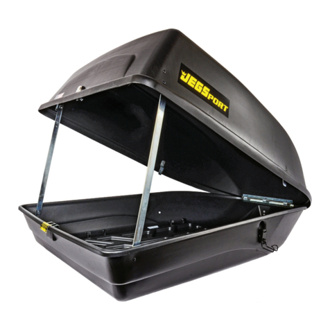
Jegs 90098 User manual

Jegs

Jegs 90098 User manual

Jegs 90093 User manual

Jegs

Jegs 90093 User manual

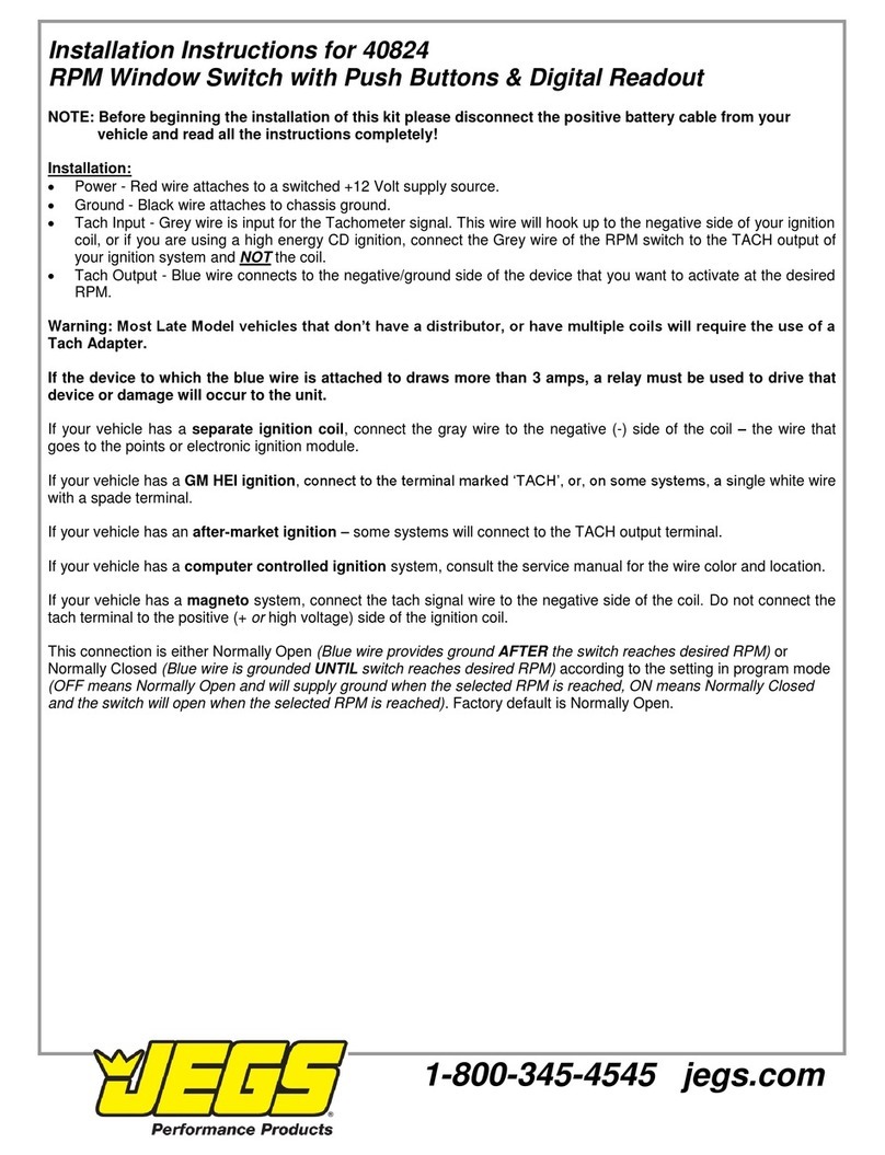
Jegs 40824 User manual

Jegs

Jegs 40824 User manual

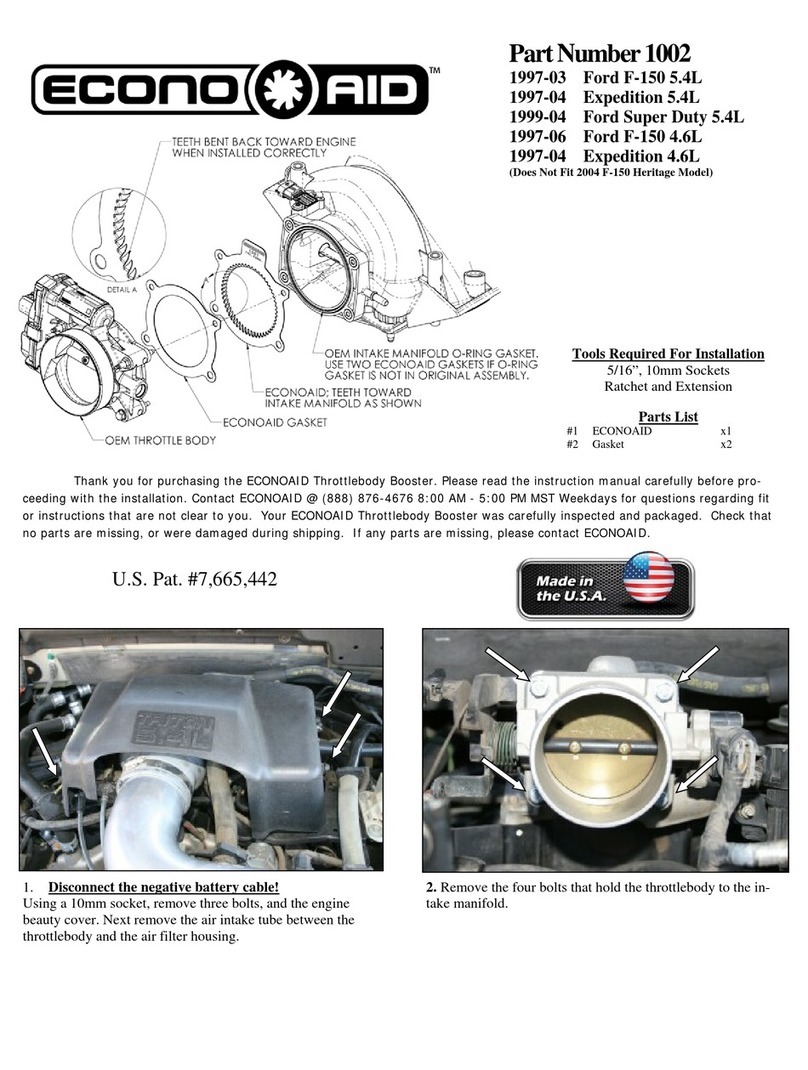
Jegs ECONOAID 1002 User manual

Jegs

Jegs ECONOAID 1002 User manual

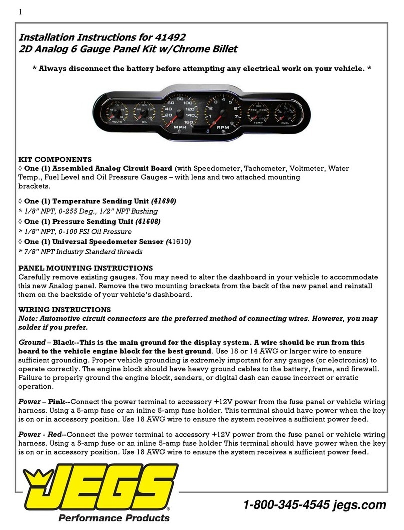
Jegs 41492 User manual

Jegs

Jegs 41492 User manual

Popular Automobile Accessories manuals by other brands

Trapeze Ranger 7-RNGR-04X Hardware installation guide

Trapeze

Trapeze Ranger 7-RNGR-04X Hardware installation guide

GripSport Van Rack Assembly instructions

GripSport

GripSport Van Rack Assembly instructions

Prorack K533 Fitting instructions

Prorack

Prorack K533 Fitting instructions

Corvette BLU-C5 install guide

Corvette

Corvette BLU-C5 install guide

KMS IB/IA23 manual

KMS

KMS IB/IA23 manual

Westin 65-1305 installation instructions

Westin

Westin 65-1305 installation instructions

Scosche IPFMRDS quick guide

Scosche

Scosche IPFMRDS quick guide

Belkin TuneBase FM with Hands-Free user manual

Belkin

Belkin TuneBase FM with Hands-Free user manual

Nav TV C.O.D-F50 manual

Nav TV

Nav TV C.O.D-F50 manual

Kuda-Phonebase 291410 Installation instruction

Kuda-Phonebase

Kuda-Phonebase 291410 Installation instruction

Whispbar K927 instructions

Whispbar

Whispbar K927 instructions

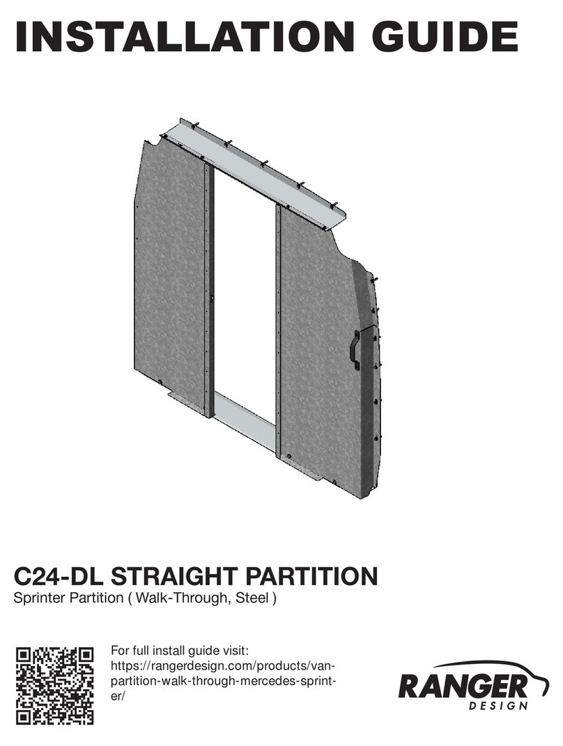
Ranger design C24-DL installation guide

Ranger design

Ranger design C24-DL installation guide

Prorack K182 Fitting Instructions for Basic Carrier

Prorack

Prorack K182 Fitting Instructions for Basic Carrier

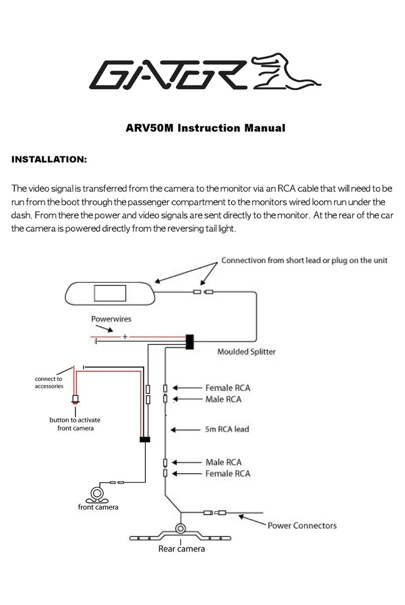
Gator ARV50M instruction manual

Gator

Gator ARV50M instruction manual

Prime Tech Roof top Tent user manual

Prime Tech

Prime Tech Roof top Tent user manual

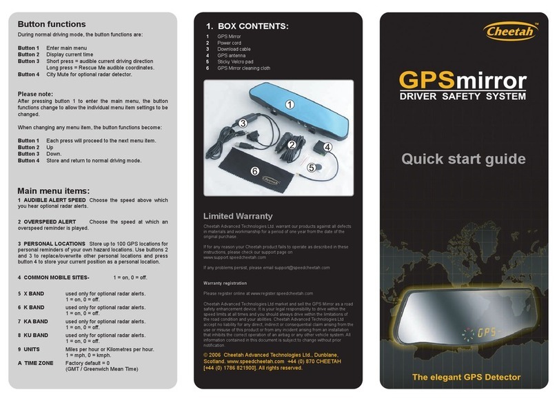
Cheetah GPS mirror quick start guide

Cheetah

Cheetah GPS mirror quick start guide

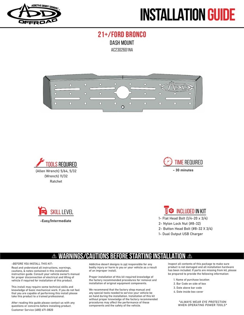
Addictive Desert Designs AC2302601NA installation guide

Addictive Desert Designs

Addictive Desert Designs AC2302601NA installation guide

CipherLab 9500CE Series Quick installation

CipherLab

CipherLab 9500CE Series Quick installation

manuals.online logo
manuals.online logoBrands
  • About & Mission
  • Contact us
  • Privacy Policy
  • Terms and Conditions

Copyright 2025 Manuals.Online. All Rights Reserved.