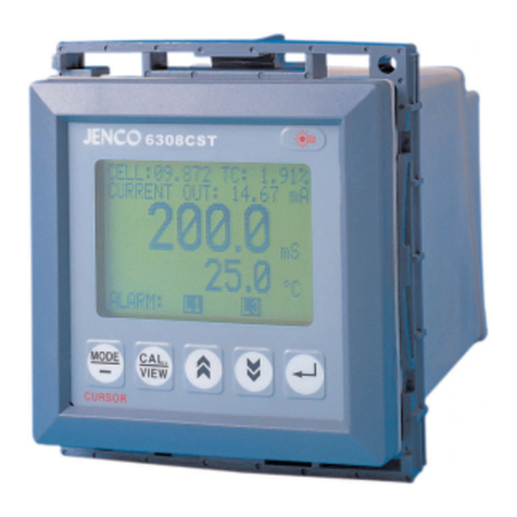
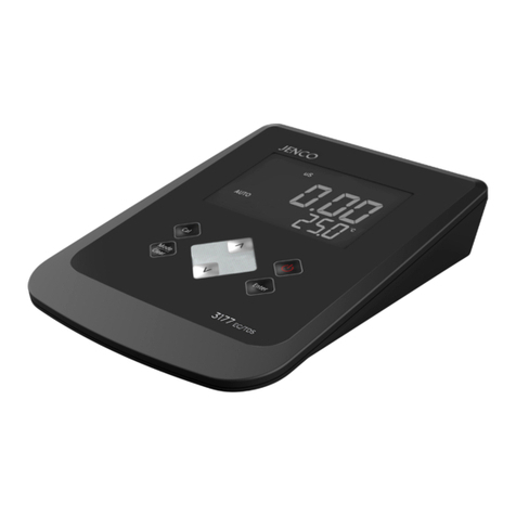
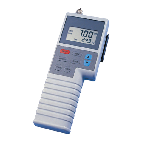
JENCO 3175-307A User manual

台式电导率计说明书
MODEL 3175-307A
沪制02270148号
3175-307A

目录
概述………………………………………………………….2
产品检视……...……………….........................................2
电源……………..…….……...………………....................2
安装电池..……………………………………....................2
显示及按键功能……………………...……………...…………3
A. 显示 .....................................................................3
B. 按键......................................................................4
操作步骤..……................................................................5
A. 标准溶液的配制......................................................5
B. 电导率校正.............................................................5
C. 电导率测量.............................................................7
错误显示及原因………………………………………........8
规格………………..…….................................................9
质量保证……………………………….........................10
1

2
概述
感谢您选购3175-307A/3175-307。 3175-307A/3175-307是一台测量
电导率、TDS(3175-307A)及温度的精密仪器,内建的微处理器可用
来存储、校正和补偿所有有关电导率、TDS及温度数据。
本仪器拥有IP54等级的防水外壳,机械式按键提供高可信任度,高
触觉及声响告知等功能,可使用9V交流电源适配器为电源,也可使用6节7
号(AAA)电池为电源。本仪表有低电(BAT)提示功能。校正数据永
久储存在主机中,下次开机时不需再次校正。
本仪器使用大型带背光的LCD,可同时显示电导率/TDS(3175-307A),
温度及指示目前所在的显示模式,即使在校正或测量程序下,也会提
供使用者各种提示。
本仪器可以很方便的选择不同的探头,用户可选择四种类型的探头
(0.01,0.1,1.0,10.0),以便于做更精确的测量。整机可显示℃的电导
率值与TDS值,此显示可通过按“MODE”键实现(3175-307A)。
其他功能包括自动切换量程,自动温度补偿以及50/60Hz交流噪声排
除能力,此仪器适合实验室使用。
产品检视
小心地打开包装,检视仪器及配件是否有因运输而损坏,如有发现,
请立即通知 JENCO 的代理。
电源
3175-307A/3175-307可用230V~9V的交流电源适配器也可用6节
“AAA”级的碱性电池提供电源。在使用仪器之前,请先检查交流适配
器上的标签,以确保电源是正确的。如果发现交流电源适配器有误,请
及时通知JENCO的代理。
[注意:如果没有正常的交流电,请使用电池供电。]
安装电池
3175-307A/3175-307使用6节7号(“AAA”)电池,以下是安装步骤:
1. 用双手掰开电池盖卡扣,取下电池盖。(图1)
2. 取出旧电池并装上新电池,更换时,请注意电池极性放置要正确。

3. 放回电池盖,并确保卡扣卡紧。
图一: 电池安装图
显示及按键功能
A. 显示
1
2
3
4
5
6
7
8
9
10
11
图二: LCD 显示
1. mS-
mS,电导度单位。 7. mg/L-
mg/L,TDS(总固体溶解量)单
位(3175-307A)。
2. BAT-
低电显示,表示须更换电池。 8. CELL K=
表示电导探棒的 K 值。
3. uS-
uS,电导度单位。
9. %/ ℃-
表示温度系数。
3

4. CAL-
当“CAL”显示时,表示整机进
入校正模式。
10. 主显示-
3175-307 显示电导率值。
3175-307A 显示电导率值和 TDS
(总固体溶解量)值。
5. AUTO-
表示整机自动切换测量范围。 11. 次显示-
显示温度值。
6. ATC/MAN-
ATC, 表示电导率读值具有温度
补偿(3175-307A)。.
MAN, 表示电导率读值不具有温
度补偿(3175-307)。
B. 按键
On/Off-
按住此键 5 秒打开或关闭主机。开机后,即按此键,
可打开或关闭主机背光。
Cal Cal-
按此键可进入校正模式。
Mode-
选择仪器的测量模式。
Clear
3175-307A 连续按此键,显示的顺序为:带温度补偿的/
无温度补偿的电导率、TDS 值(总固体溶解量)。
3175-307 无此键,显示无温度补偿的电导率值。
or
Clear
Mode
Clear-
清除键。在测量模式下,除非长按此键 5 秒,机器会
删除所有校正值,否则此键不起作用,目的是防止用
户由于误触而删除校正值。
上键和下键
上键和下键仅在校正模式才起作用,增加、减少需变
动的设置项目值。在测试状态不起作用。
4

Enter Enter-
在校正状态按此键,把当前的设定值记忆到微处理中。
操作步骤
A. 标准溶液的配制
适宜的标准溶液配制粉剂需使用商业用或研究用等级的粉剂,以下是
三种浓度的标准溶液的配制方法,使用者可以用它们来校正
3175-307A/3175-307的电导电极。
1. 1413uS 标准溶液(25℃): 精确地称量0.746 g研究用等级的KCL,
使它溶解于1000ml的纯水中。
2. 12.90mS标准溶液(25℃): 精确地称量7.4365 g研究用等级的
KCL,使它溶解于1000ml的纯水中。
3. 111.9mS标准溶液(25℃): 精确地称量74.264 g研究用等级的
KCL,使它溶解于1000ml的纯水中。
[注意:剩余的未经使用过的标准溶液,您可以用密闭的容器在
低于 4 摄氏度的环境下储存一周。如果您对标准溶液准确性产生
疑问,请重新配制新的标准溶液。]
B. 电导率校正
校正步骤包含6个步骤:TDS因数、温度系数、参考温度、电导电极常
数种类选择、校正标准溶液方式调整电导电极常数以及直接调整电导
电极常数校正。详细步骤如下:
1. 将电导电极的接头与主机的接口连接并按开关键开机。
2. 等温度读值稳定后,请按“Cal” 键进入校正模式,“CAL”将
显示在LCD上。
TDS因数
TDS(总固体溶解量)是用有温度补偿的电导值乘以TDS因数值
取得,机器默认值为0.65。你可以用上键和下键调节这个TDS
因数值,调整范围是0.30~1.00。按“Enter”键储存新的设定
值并进入下一个校正参数界面。
5

6
温度系数
整机是用温度系数计算具有温度补偿的电导率值的,此温度系
数默认值为1.91%. 你可以用上键和下键调节这个温度系数值,
调整范围是0.00~4.00%。按“Enter”键储存新的设定值并进入
下一个校正参数界面。
参考温度
整机是用参考温度来计算具有温度补偿的电导率值的,此参考
温度默认值为25℃。你可以用上键和下键调节这个参考温度值,
调整范围是15~ 25℃。按“Enter”键储存新的设定值并进入下
一个校正参数界面。
电导电极常数种类选择
整机主显示将显示一个电导电极常数 (上次使用校正过的或默
认的,此值的调整范围是70%~130%)。次显示将显示电导电极种
类,你可以用上键和下键选择电极常数种类,此整机有四种电
极常数种类 (0.01, 0.1,1.0 and 10.0)。按“Enter”键储存
新的设定值并进入下一个校正参数界面。
校正标准溶液方式调整电导电极常数校正
(a) 把电导电极放入已知电导率标准溶液中(详见“标准溶液的
配制”), 此标准溶液的选择最好基于被测溶液电导值的范围
之内。
(b) 把电极浸入标准溶液中(至少2~3英寸或者5~7cm),并稍作
搅动以便消除电极极片上的空气泡。整机将显示标准溶液的
电导率值。在校正步骤中,请先确认以下参数已设定完成:
温度系数设成1.91%,参考温度设成25.0℃。
[注意: 如果你想直接用输入常数值调整,请按“Enter”键
进入“直接调整电导电极常数校正”。]
(c) 稍等片刻,等待温度稳定。当温度稳定后,你可以用上键和
下键调节这个标准的电导度值(25℃)。按“Enter”键储
存新的设定值并进入下一个校正参数界面。

7
直接调整电导电极常数校正
(a) 整机将显示标准溶液的电导率值,“CELL K=”也将显示在
LCD 上,表示此校正时直接调整电导电极常数。
[注意: 如果你已用“校正标准溶液方式调整电导电极常
数”,请按“Enter”键退出校正模式回到测量模式。]
(b) 按住“上键” 或 “下键”, 主显示将显示电导电极常数
偏差并同时增加或减少此值(此值可从70%~130%)。放开“上
键” 或 “下键”,主显示将显示标准溶液的电导率值。
(c) 调动此电导电极常数值,使得电导率值与25℃的标准溶液值
一致。按“Enter”键储存新的设定值并退出校正模式回到
测量模式。
C. 电导率的测量
1. 电极接上整机后,开机,把清洗后的电极直接放入被测溶液中
(至少浸没2~3英寸或者5~7cm),稍做搅动,赶出电极片
上的空气泡。
2. 按“Mode”键切换到自己需要测量的参数(电导率或 TDS)。
机器在自动切换量程的时候显示“over”或“undr”是正常的。
当温度稳定后,就可以读取测量值,此值才为被测溶液的测量
值。
[注意: 3175-307 无“Mode”键,因此无切换功能,整机显示无
温度补偿的电导率值。]

错误显示及原因
主显示 次显示 可能发生原因 纠正错误
测量模式显示
"over"
●无法检测样品。
8
[注意:如果机器仍然不能正常工作,请联系Jenco的服务部门。]
0.0~100.0℃
●被测溶液电导率
值> 200.0mS;
被测溶液 TDS值
> 200g/L。
.
●清洗电极或更换电
极。
●电导电极受污
染或已损坏。
●输入的电极常
数值不正确。
●正确输入电极常数
值。
校正模式显示
"over" /
●标准溶液错误。
●电导电极受污染
或已损坏。
●输入的电极常数
值不正确。
●更换标准溶液。
●清洗电极或更换电
极。
●正确输入电极常数
值。
●被测溶液温度
>100℃。
●降低被测溶液温度。
over
●电导电极损坏。●更换电极。
●被测溶液温度
<0.0℃。
●升高被测溶液温度。
测量模式显示
"over"
undr
●电导电极损坏。●更换电极。

9
规格
显示 测量范围 分辨率 精确度
电导率
K=0.01
0.000 to 1.999uS/cm
2.00 to 19.99uS/cm
0.001uS/cm
0.01uS/cm
±0.5% 全量程
±0.5% 全量程
电导率
K=0.1
0.00 to 19.99uS/cm
2.0 to 199.9uS/cm
0.01uS/cm
0.1uS/cm
±0.5% 全量程
±0.5% 全量程
电导率
K=1.0
0.0 to 199.9uS/cm
200 to 1999uS/cm
2.00 to 19.99mS/cm
0.1uS/cm
1uS/cm
0.01mS/cm
±0.5% 全量程
±0.5% 全量程
±0.5% 全量程
电导率
K=10.0
0 to 1999uS/cm
2.00 to 19.99mS/cm
20.0 to 199.9mS/cm
1uS/cm
0.01mS/cm
0.1mS/cm
±0.5% 全量程
±0.5% 全量程
±0.5% 全量程
温度 0.0 to 100.0 °C 0.1 °C ±0.2°C
参考温度 15.0 to 25.0 °C
温度系数 0.0% to 4.0%
电导电极常数 0.01; 0.10; 1.00; 10.0
TDS因数(3175-307A)0.30 to 1.00, 默认为0.65
电源 6节7号(“AAA”)电池及稳压源
校正存储 EEPROM
音效回馈 所有按键
终点锁定 有
显示 (pH /mV : 温度) 22mm : 14.5mm 高LCD
环境温度 0 ~ 50 °C
相对湿度 90%以下
外壳 IP54
尺寸 (长 x 宽 x 高) 150mm x 203mm x 72mm

10
质量保证
仪器保修一年(以购买日为准)。在保修期内如有质量问题,本
公司将无偿代为修复;如有人为因素造成故障或损坏,本公司竭
诚代为修复,但需酬收工本费(配件如电极头、标准液等消耗品
不在保证范围内)。在将本机退回本公司时,请用包装材料妥为
包好,以避免运输途中碰伤。无论何种情况,在退回本机前,请
先与本公司联系,并得到本公司认可,方可退回本机。
JENCO (中国)公司:上海任氏电子有限公司
地址:上海市松江区泗泾镇望东中路18号
邮编:201601
电话:57619600,57619008
传真:57619240

CONTENTS
GENERAL INTRODUCTION………………..................12
INITIAL INSPECTION……...………………..................12
POWER INPUT..…….……...………………..................12
INSTALLING THE BATTERIES..…………..................13
DISPLAY & KEYS FUNCTIONS…..……………...……14
A. Display ..............................................................14
B. Keys...................................................................15
OPERATIONAL PROCEDURES..…….......................16
A. Preparing Standard Solutions..............................16
B. Calibration......................................................16
C. Conductivity Measurements..................................18
ERROR DISPLAYS AND TROUBLESHOOTING.......19
SPECIFICATIONS………………..……........................20
WARRANTY………………………….........................21
11

12
GENERAL INTRODUCTION
Thank you for selecting the 3175-307A/3175-307meter. The
3175-307A/3175-307 is a precision tool that measures Conductivity,
TDS(3175-307A) and Temperature. A built-in microprocessor
stores, calculates and compensates for all parameters related to
Conductivity, TDS and Temperature determinations.
This meter has a waterproof IP54 case. The mechanical keys are
highly reliable with tactile and audio feedback. This meter is
powered by six AAA-size alkaline batteries or with a UL approved
AC adapter (OUTPUT: DC9V). The meter also displays a “BAT”
message when the batteries are in need of replacement.
Re-calibration is not required when power is restored.
The front of the meter has a large LCD that displays Conductivity or
TDS and Temperature simultaneously along with user prompts and
mode indicators. The unit prompts the user through calibration and
measurement procedures.
The model 3175-307A/3175-307 micro-processor allows the user to
easily recalibrate the parameters for the probe. A few keystrokes will
adjust all the parameters for conductivity and will also give the user
the option to select four types (0.01, 0.1, 1.0, 10.0) of probe cell
constant for a better selection of available probes and applications.
And the user can input K value of the cell by keypad directly.
The system simultaneously displays temperature in ℃along with
either Conductivity or TDS. The user can switch back and forth from
all these displays by just pushing a single “MODE” key
(3175-307A/3175-307).
Other features include automatic conductivity ranging, automatic
temperature compensation, long battery life, and 50/60 Hz AC noise
rejection. This meter is user-friendly for laboratory application.
INITIAL INSPECTION
Carefully unpack the unit and accessories. Inspect for damages
made in shipment. If any damage is found, notify your Jenco
representative immediately. All packing materials should be saved
until satisfactory operation is confirmed.
POWERINPUT
The model 3175-307A/3175-307 can be powered by an 115V or
230VAC adaptor as well as 6 “AAA” alkaline batteries. Check the
label on the AC

adaptor supplied with the instrument to make sure that the AC line
voltage is correct. If the wrong AC adaptor is supplied, notify your
Jenco representative immediately.
INSTALLING THE BATTERIES
To insert the batteries into the meter, follow the procedure outlined
below.
1. Use two hands to flip the two buckles and battery cover to
expose the battery compartment. (Figure 1.)
2. Note the polarity and insert the six AAA batteries into the
battery compartment correctly.
3. Replace the battery cover.
Figure 1: Battery compartment
13

DISPLAY & KEYS FUNCTIONS
A. Display
1
2
3
4
5
6
7
8
9
10
11
Figure2: Active LCD screen
1. mS- 7. mg/L-
Millisiemens , indicates Milligrams/Liter indicates TDS
measurement(3175-307A).
Conductivity measurement.
2. BAT- 8. CELL K=
Low battery indicator. Indicates conductivity cell
constant value.
3. uS- 9. %/ ℃-
Microsiemens, indicates Indicates Temperature
Coefficient
Conductivity measurement.
4. CAL- 10. MAIN DISPLAY-
This will be displayed when the
unit enters into the calibration
mode.
For Conductivity and TDS
values (3175-307A).
For Conductivity values
(3175-307).
5. AUTO- 11. SECONDARY DISPLAY-
For temperature in ℃display.
Auto ranging indicator
6. ATC/MAN-
ATC, indicates Compensated
Conductivity (3175-307A).
MAN, indicates
Uncompensated Conductivity
(3175-307).
14

B. Keys
On/Off-
Press and hold this key for 5 seconds to power on
and shut off the meter. Once the unit is power up,
press the same key to turn on or off the backlight.
Cal
Cal-
During normal operation, this key will change the
mode from “Measure” mode to “Calibration” mode.
Mode-
3175-307A selects display mode. In normal
operation, press this key to sequentially display
Compensated Conductivity / Uncompensated
Conductivity and TDS.
Clear 3175-307 has not this key. It displays
Uncompensated Conductivity.
or
Clear
Mode
Clear-
When this key is pressed, it clears all calibration
values stored in the internal memory.
Under normal use the key will not be activated unless
pressed and held for 5 seconds to prevent accidental
erasing stored memory.
Up/Down-
Increases or decreases the display value as desired.
Enter
Enter-
In Calibration mode, press this key to save the
current parameter to memory.
15

16
OPERATIONALPROCEDURES
A. Preparing Standard Solutions
Suitable conductivity standards are available commercially or the
user can prepare them using research grade reagents.
Here are some standard solutions the user can prepare to calibrate
the probe of the model 3175-307A/3175-307.
1. Standard solution of 1413uS at 25℃: Accurately weight out
0.746 grams of research grade dried Potassium Chloride
(KCL). Dissolve in 1000ml of distilled water.
2. Standard solution of 12.90mS at 25℃: Accurately weight out
7.4365 grams of research grade dried Potassium Chloride
(KCL). Dissolve in 1000ml of distilled water.
3. Standard solution of 111.9mS at 25℃: Accurately weight out
74.264 grams of research grade dried Potassium Chloride
(KCL). Dissolve in 1000ml of distilled water.
[Note: You can store the remaining solution in a plastic
container for one week but the air space between the cap and
the solution must be kept to an absolute minimum. Storing the
excess solution below 4℃can increase the storage life. If you
have any doubt of the accuracy of the stored solution, a fresh
batch should be prepared.]
B. Calibration
Calibration setup contains six sections: TDS Constant, Temperature
Coefficient, Temperature Reference, Probe Basic Cell Constant,
Cell Constant Calibration and K Value Input. To access these
sections:
1. Connect the conductivity probe to the unit and turn the unit
on.
2. Allow temperature reading to stabilize, press “Cal” key to
enter the calibration mode. CAL appears on the LCD.
[Note: Press “Enter”key to accept any values changes in
each section and automatically advance to the next section. If
there are no changes, the unit accepts the current value and
proceeds to the next section.]

17
TDS Constant
TDS is determined by multiplying conductivity (mS) by a TDS
factor. The default factor value is 0.65. To change the TDS
factor, use the “up” and “down” keys to adjust the value
between 0.30 and 1.00. Press “Enter” key to save the new
value and go to the next calibration parameter.
Temperature Coefficient
The unit uses the temperature coefficient to calculate
temperature compensated conductivity. The default value is
1.91%. To change the Temperature Coefficient, use the “up”
and “down” keys to adjust the value between 0 and 4.00%.
Press “Enter” key to save the new value and go to the next
calibration parameter.
Temperature Reference
The unit uses the temperature reference value to calculate
temperature compensated conductivity. The default value is
25℃. To change the Temperature Reference, use the “up”
and “down” keys to adjust the value between 15 and 25℃.
Press “Enter” key to save the new value and go to the next
calibration parameter.
Probe Basic Cell Constant
The main display shows the deviation of the conductivity probe
(calibrated previously or default, the deviation range is
70%~130%, 100% without error). The secondary display
shows the current selected cell constant. Using the “up” and
“down” keys to adjust the probe basic cell constant to that you
use from the 4 available cell constants (0.01, 0.1,1.0 and 10.0).
Press “Enter” key to save the new value and go to the next
calibration parameter.
Cell Constant Calibration
(a) Immerse the probe in a standard of known conductivity
solution (See section Preparing Standard Solutions),
preferably a standard in the middle range of the solutions
to be measured. Immerse the probe (at least 2” to 3” or
5~7cm from the tip) without touching the sides of the
calibration container. Shake the probe lightly to remove
any air bubbles trapped in the conductivity cell. The unit
will display the conductivity value of the standard solution.
During cell constant calibration, the following parameters

18
are over-ridden: temperature reference (fixed to 25.0℃) and
temperature coefficient (fixed to 1.91%).
[Note: If you want input K value directly, please press the
“Enter” key to go to the K Value Input.]
(b) Wait for the values of temperature and conductivity to
stabilize for a few seconds. Using the “up” and “down”
keys to adjust the reading of the display until it matches
the value of the known standard conductivity solution at 25
℃.
(c) Press “Enter” key to calculate and save the new value of
Cell Constant or press the “Enter” key to the next
calibration parameter.
K Value Input
(a) The unit will display the conductivity value of the standard
solution with the CELL K= staying on.
[Note: If the Cell Constant has been calibrated, please
press the “Enter” key to exit calibration and return to
normal operation.]
(b) Press and hold the “up” or “down” key, the main display
will show the deviation of the conductivity probe. You can
now input the K value (from 70%~130% of the probe basic
cell constant). After releasing the up or down key, the unit
will display the conductivity value with the CELL K=
staying on.
(c) adjust the K value until the conductivity value displayed on
the LCD matches the value of the known standard
conductivity solution at 25℃.
(d) Press “Enter” key to save the new K value of the cell to
exit calibration and return to normal operation mode.
C. Conductivity Measurements
1. Turn the unit on. Place the probe in the solution to be
measured. Immerse the probe (at least 2” to 3” or 5~7cm from
the tip). Shake the probe lightly to remove any trapped air
bubbles in the conductivity cell.
2. Press “Mode” key to enter the desired measurement mode
(Conductivity or TDS). The message “over” or “undr” may
appear briefly on the display indicate auto-ranging; this is

19
normal. Allow temperature to stabilize before taking
measurements.
ERROR DISPLAYS AND TROUBLESHOOTING
[Note: If the meter still does not perform normally after the above
measures are taken, call Jenco representative.]
Main
Display
Secondary
Display Possible
cause(s) Corrective
Action(s)
"over" during
measurements
0.0~100.0℃
●Sample
Conductivity
value >
200.0mS;
Sample TDS >
200g/L.
●Sample cannot be
tested
●Conductivity
cell
contaminated o
r
defective.
●Incorrect K
constant value
input.
.
●Decontaminate /
clean cell or replace
cell.
●Input correct K
value.
●Incorrect
standard
solution.
●Conductivity
cell
contaminated o
r
defective.
"over" during
calibration /
●Incorrect K
constant value
input.
●Replace standard
solution.
●Decontaminate /
clean cell or
replace cell.
●Input correct K
value.
●Sample
temperature
>100℃.
●Reduce sample
temperature.
over ●Defective
conductivity
cell.
●Replace cell.
●Sample
temperature
<0.0℃
●Increase sample
temperature.
"over " during
measurements
undr ●Replace cell.
●Defective
conductivity
cell.
Table of contents
Other JENCO Measuring Instrument manuals
JENCO
JENCO 6173 User manual

JENCO
JENCO 6011M User manual

JENCO
JENCO pH610N User manual

JENCO
JENCO 6250 User manual

JENCO
JENCO 6010N User manual

JENCO
JENCO 9031M User manual

JENCO
JENCO 3177M User manual

JENCO
JENCO 6179MB User manual

JENCO
JENCO VisionPlus 9020M User manual

JENCO
JENCO VisionPlus pH630 User manual
Popular Measuring Instrument manuals by other brands
SKF
SKF TMRT 1 Instructions for use

Pfeiffer Vacuum
Pfeiffer Vacuum TPG 300 operating instructions

Bante Instruments
Bante Instruments TB200 user manual

ARAG
ARAG DigiWOLF 4627 Series Installation, use and maintenance

Waeco
Waeco MAGIC Control MTPM-100 Installation and operation manual

Vutility
Vutility HotDrop installation guide