JENCO 6360 User manual

Operation Manual
JENCO MODEL 6360
MICROCOMPUTER BASED
pH/mV/Conductivity/TDS/
Salinity/Temperature
PORTABLE METER
6360

CONTENTS
GENERAL INTRODUCTION………………....................1
INITIAL INSPECTION……...………………....................2
WATER PROOF…….……...………………....................2
INSTALLING THE BATTERIES..…………....................3
DISPLAY & KEYS FUNCTIONS…..……………...………4
A. Display ................................................................4
B. Keys...................................................................6
OPERATIONAL PROCEDURES..…….........................8
A. Preparing Standard Solutions................................8
B. Calibration..........................................................9
C. Conductivity Measurements..................................13
D. Save, Recall and Delete Data.................................13
RS232C INTERFACE OPERATION........................... 15
ERROR DISPLAYS AND TROUBLESHOOTING.......16
SPECIFICATIONS………………..……........................18
WARRANTY……………...............................................19
1
GENERAL INTRODUCTION
Thank you for selecting the 6360 meter. The 6360 is a precision tool
that measure pH, ORP, conductivity, TDS, salinity and temperature.
A built-in microprocessor stores, calculates and compensates for all
parameters related to conductivity and temperature determinations.
This unit has a waterproof IP65 case. The touch mode keys are
highly reliable with tactile and audio feedback. This meter can
operate with six AAA-size alkaline batteries or a UL/CE approved
AC adapter. Re-calibration is not required when power is restored.
The front of the meter has a large LCD that displays temperature
and either temperature compensated or non-temperature
compensated conductivity, pH, ORP, temperature compensated
TDS or salinity simultaneously along with user prompts and mode
indicators. The unit prompts the user through calibration and
measurement procedures.
The unit is also equipped with a non-volatile memory allowing the
user to store 50 different sets of readings. This unit will assign a site
number for each set of reading so the user can review the data
easily.
The model 6360 is available with a four-wire conductivity cell
(K=0.475) and a two-wire conductivity cell (K=0.1). Other features
include automatic conductivity ranging, automatic temperature
compensation, long battery life and 50/60 Hz AC noise rejection.
This unit is universal and user-friendly for field, industrial and
laboratory applications.
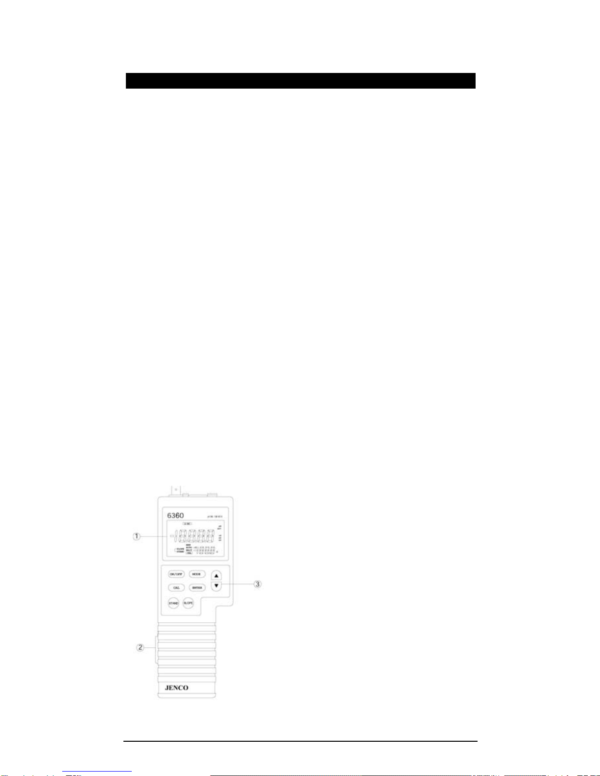
①LCD
②RS232 connector
③Keypad

2
INITIAL INSPECTION
Be careful to unpack the unit and accessories. Inspect for damages
made in shipment. If any damage is found, notify your Jenco
representative immediately. All packing materials should be saved
until satisfactory operation is confirmed.
WATER PROOF
Though this unit has a waterproof IP65 case, DO NOT use it
underwater. The watertight case prevents permanent damage to the
unit if accidentally dropped into non-corrosive solutions. Follow
these steps immediately if the unit is immersed in any solution:
1. Rinse unit carefully with distilled water. After rinsing and drying,
inspect and clean connectors to remove all contaminants that
may affect probe connections.
2. Wait for the unit and probe to dry completely before resuming
operation.
3. If the unit does not function correctly after step 1 and 2, call
JENCO for possible repair or replacement (see Warranty).

3
INSTALLING THE BATTERIES
The 6360 meter is packaged with six AAA-size alkaline batteries or
a UL/CE approved AC adapter, required for operation. To insert the
batteries into the meter, follow the procedure outlined below.
Figure 1: Battery compartment
1. Position the meter so that the bottom part of the meter is
facing up . Insert a coin in the side closure slot. Tilt the coin
and thrust it upward to open the battery compartment and
lift the closure up.
2. Remove all of the old batteries and insert a new set of
batteries ensuring the polarities are correct.
AAAbattery
BatteryCover
SIDE CLOSURE SLOT

4
DISPLAY & KEYS FUNCTIONS
A. Display
Figure 2: Active LCD screen
1. LO BAT-
Low battery indicator.
4. %-
Displays during calibration:
Indicates temperature coefficient
unit.
2. Main Display-
Display the reading of pH,
ORP, Conductivity, TDS &
Salinity.
5. Main Display Units-
“pH”: pH mode unit.
“mV”: ORP mode unit.
“uS, mS”: Conductivity mode unit.
“ppm, ppt”: TDS and Salinity
mode unit.
3. SALINITY-
Display that the unit is in the
SALINITY mode.
6. ℃/℉-
Temperature unit.
In Uncompensated Conductivity
mode, the temperature unit will
not blink.
In Compensated Conductivity
mode, the temperature unit will
blink.

5
7. Secondary Display-
Temperature reading and
site number.
10. AUTO/MAN-
“AUTO”: Used to indicate that a
temperature sensor is attached.
“MAN”: Used to indicate that a
temperature sensor is not
attached and the pH temperature
compensation is manual.
8. WAIT/CAL-
“WAIT”: Used when in pH
calibration to indicate that the
reading is not yet stable.
“CAL”: Used to indicate that
unit is in calibration mode.
11. RC-
Indicate that the unit is in recall
mode and actively displaying
saved data.
9. STAND/SLOPE-
During calibration this will
indicate which part of pH is
being calibrated, in normal
operation this will indicate
(blinking) which part of pH is
not yet calibrated.

6
B. Keys
ON/OFF-
Powers on and shuts off the meter.
MODE-
Selects display mode. In normal operation, press this
key to sequentially display pH, ORP, uncompensated
conductivity, compensated conductivity, TDS,
salinity, Recall and Erasing interface.
In calibration mode, press this key to exit the current
calibration parameter and enter into the next one.
In “rcl” and “ErAS” modes, press this key to exit “rcl”
and “ErAS” modes respectively.
UP/DOWN-
Increases or decreases the display value as desired.
In “rcl” mode, view saved data and data storage site
number by pressing these keys.
CAL-
In “Measurement” mode, press this key to enter into
“Calibration” mode.
In pH mode, press this key can enter the pH
calibration.
In conductivity or salinity or TDS mode, press this
key can change TDS ,conductivity constant ,
temperature coefficient, reference temperature,
compensated conductivity.
ENTER-
In “Calibration” mode, press this key one time to save
the current value to memory.
In “Measurement” mode, press this key 5 seconds to
save reading into the next available data storage site.
In “rcl” mode, press this key to display the last set of
saved data.
In “ErAS” mode, press this key to erase all data.

7
STAND
STAND-
During pH calibration press this key will start the
calibration of the OFFSET of the pH electrode.
Press this key with ON/OFF when the instrument is
off, the unit will acknowledge by displaying “7.00” for
(7.00,4.01,10.01) and “6.86” for (6.86,4.00 & 9.18) in
the second interface after turning on.
SLOPE SLOPE-
During pH calibration this key will start the calibration
of the SLOPE of the pH electrode.

8
OPERATIONALPROCEDURES
A. Preparing Standard Solutions
Suitable conductivity standards are available commercially, the user
can prepare them using research grade reagents.
Here are some standard solutions the user can prepare to calibrate
the probe of the model 6360.
1. Standard solution of 14.94uS at 25℃: Accurately measure out
100ml of the 147uS standard solution as in point 4. Dilute it
with 900ml of distilled water.
2. Standard solution of 147uS at 25℃: Accurately measure out
100ml of the 1413uS standard solution as in point 1. Dilute it
with 900ml of distilled water.
3. Standard solution of 1413uS at 25℃: Accurately weight out
0.746 g of research grade dried Potassium Chloride (KCL).
Dissolve in 1000ml of distilled water.
4. Standard solution of 12.90mS at 25℃: Accurately weight out
7.4365 grams of research grade dried Potassium Chloride
(KCL). Dissolve in 1000ml of distilled water.
5. Standard solution of 111.9mS at 25℃: Accurately weight out
74.264 grams of research grade dried Potassium Chloride
(KCL). Dissolve in 1000ml of distilled water.
[Note: The user can store the remaining solution in a plastic
container for one week but the air space between the cap and the
solution must be kept to an absolute minimum. Storing the excess
solution below 4℃can increase the storage life. If you have any
doubt of the accuracy of the stored solution, a fresh batch should be
prepar ed.]

9
B. Calibration
BUFFER SETTING
The buffer setting is factory selected according to user
preference, but the user can change this setting by going to
normal pH reading 【Pressing [STAND] and turn on when it’s
off.】The 6360 will acknowledge by displaying “7.00” (7.00,4.01
& 10.01) or “6.86” (6.86,4.00 & 9.18) and the text “buf” at the
first display when it’s turned on then turns to normal pH
operation.
CALIBRATION SET-UP
A. STAND AND SLOPE CALIBRATION (pH Mode)
To calibrate the stand and/or slope follow these steps:
1. Go to pH mode. Press the [CAL] key, the "CAL" icon will
appear in the lower middle of the display. At this point the
unit will display the current buffer set 7.00 for buffer set #1
(7.00, 4.01 & 10.01) or 6.86 for buffer set #2 (6.86, 4.00 &
9.18). The "STAND" icon will start to flash indicating that
the first buffer to be used is 7.00 or 6.86.
2. Place the probe in a standard buffer solution (7.00 or 6.86
buffer). Press the [STAND] key.
3. The "STAND" icon will stop flashing and stay ON. The
display will change to the pH value of the current
temperature. If a temperature probe is available, the
"AUTO" icon will turn on. If the offset ORP of the solution
is greater or less than ±100 mV (for buffer 7.00) or 108.3
mV/-91.7 mV (for buffer 6.86), then an error display will
occur. You can clean the probe and change the solution,
and press [MODE] to exit the calibration. If no error occurs
the unit will wait for the reading to stabilize for about ten
seconds (during this waiting time "WAIT" icon will blink)
then it will lock the value of the display. If during
stabilization period and the reading changes more than
pH
7.00
AUTO
SLOPE
STAND CAL 25.0 °C

10
0.01 pH, the waiting time (about 10 seconds) will restart.
In this case:
A. Change the solution.
B. Stop by pressing the [MODE].
C. Wait it out until the electrode stabilizes.
Once the display is locked ( the "WAIT" icon will
disappear), changing the input or temperature will not
change the pH display.
4. The "SLOPE" icon will start to flash indicating that the
instrument is ready for the second buffer calibration. You
can press [MODE] to exit for a one-point pH calibration.
5. If you are doing a two-point calibration, change the
solution now.
Press [SLOPE]. The "SLOPE" icon will stop flashing and
stay ON. If the ORP input is greater than 30% or less than
-30% of the ideal slope of this buffer then an error display
will occur. You can change solution now or you can press
[MODE] to abort the SLOPE Calibration. If no error occurs
the unit will wait for the reading to stabilize (during this
waiting time "WAIT" icon will blink) then it will lock the
value of the display. If during stabilization period and the
reading changes more than 0.01 pH then this waiting time
(about 10 seconds) will restart .
In this case :
A. You can change the solution.
B. Just abort by pressing [MODE].
C. Wait it out until the electrode stabilizes.
Once the display is locked (the "WAIT" icon will disappear)
changing the input or temperature will not change the pH
display.
You just finished a two-point pH calibration. Press [MODE]
to return you to normal operation. The instrument is now
ready for pH measurements.
B. COND CALIBRATION
Calibration setup contains five parameters: TDS, Cell,
Temperature Coefficient, Temperature reference and
Conductivity Calibration with Temperature reference. To access
these sections:
1. Connect the conductivity probe which model is either the
101C (K=0.475) or the 109L(K=0.1) to the unit and turn it
on. The screen will display the “C0.5” “C0.1” icon and the
cell constant of the previous calibration. (Factory default
is set at K=0.475).
2. Allow temperature reading to stabilize, in the mode of
either temperature compensated or non-temperature
compensated conductivity, temperature compensated
TDS or salinity, press “CAL” key to enter the calibration

11
mode. The “CAL” icon appears on the LCD. Press “UP”
and “DOWN” key to change the value, press “ENTER” key
to save the setting and go into the next setting. If pressing
“MODE” key instead of “ENTER” key, the setting will be
given up and go into the next setting.
TDS
TDS is determined by multiplying conductivity (mS) by a TDS
factor. The default factor value is 0.65. To change the TDS
factor, use the “UP” and “DOWN” keys to adjust the value
between 0.30 and 1.00. Press “ENTER” key to save the new
value and the unit will go into the next calibration parameter
automatically. If pressing “MODE” key instead of “ENTER” ,
any changes made will be cancelled and the previous
calibration settings will be retained.
CELL
Press “UP” and “DOWN” keys to select cell constant “C0.5” or
“C0.1” on the secondary display. Press “ENTER” key to
confirm selection, then the unit will go into the next calibration
parameter automatically. If “MODE” key is pressed instead of
the “ENTER” key, any changes made will be cancelled and
the previous calibration settings will be retained.
0.65
CAL TDs
0.475
CAL c0.5
12
Temperature Coefficient
The unit uses the temperature coefficient to calculate
temperature compensated conductivity. The default value is
1.91%. To change the temperature coefficient, use the “UP”
and “DOWN” keys to adjust the value between 0 and 4.00%.
Press “ENTER” to save the new value and the unit will go into
the next calibration parameter automatically. If “MODE” is
pressed instead of “ENTER”, any changes made will be
cancelled and the previous calibration settings will be
retained.
Temperature Reference
The unit uses the temperature reference value to calculate
temperature compensated conductivity. The default value is
25℃. To change the temperature coefficient , use the “UP”
and “DOWN” keys to adjust the value between 15℃to 25℃.
Press “ENTER” key to save the new value and the unit will go
into the next calibration parameter automatically. If “MODE”
key is pressed instead of the “ENTER” key, any changes
made will be cancelled and the previous calibration settings
will be retained.
%
1.91
CAL 25.0 ℃
25.0 ℃
CAL 25.0 ℃

13
Conductivity Calibration
(a) Immerse the probe in a standard of known conductivity,
preferably a standard in the middle range of the solutions
to be measured. Immerse the probe (at least 2” to 3” or
5~7cm from the tip) into standard solution without touching
the sides of the container. Shake the probe lightly to
remove any air bubbles trapped in the conductivity cell.
(b) Allow temperature to stabilize. The message “rAGE”
(range) may appear briefly on the display indicating
auto-ranging; this is normal. After temperature stabilization,
use the “UP” and “DOWN” keys to adjust the conductivity
value to that of the conductivity standard at 25℃. Press
“ENTER” key to calibrate. Calibration is now complete and
the unit will switch to “Measurement” mode automatically.
C. Conductivity Measurements
1. Turn on the unit. Place the probe in the solution to be
measured. Immerse the probe (at least “2 to 3” or 5~7cm
from the tip) in the sample solution. Shake the probe
lightly to remove any trapped air bubbles in the
conductivity cell.
2. Press “MODE” key to enter into the measurement mode.
The message “rAGE” (range) may appear briefly on the
display indicating auto-ranging; this is normal. Allow
temperature to stabilize read the value.
D. Save, Recall and Delete Data
a. Saving readings to memory.
1. In the modes of either temperature compensated or
non-temperature compensated conductivity, pH, ORP,
temperature compensated TDS or salinity, hold the “ENTER”
key for 5 seconds to save data. The “Save” icon with the
corresponding site number will lit up for a brief moment to
indicate a successful data to save.
oUer us
CAL 25.0 ℃

14
2. If the “Full” icon is displayed, it means that all 50 data saving
sites are used up. No new data can be saved until existing
saved data are deleted.
b. Recalling readings from memory.
1. To recall saved data, press “ENTER” key to go into the “rcl”
mode.
2. Press the “UP” or “DOWN” keys to select the storage site
number and Press “ENTER” key to go into the interface,“RC”
icon will be displayed at the top left corner. Press “ENTER” key
to change the interface of pH, ORP, conductivity, TDS, salinity
and temperature
3. Press “MODE” key to exit “rcl” mode.
c. Deleting
data.
In the “ERAS” mode, hold the “ENTER” key for 5 seconds, the
unit will display “done” icon that all the save data are deleted.
The unit will go into the pH mode automatically.
R C L
0 1
E R A S

15
RS232C INTERFACE OPERATION
A. INTRODUCTION
This section assumes you are familiar with the basics of data
communication, the RS232 interface, a rudimentary knowledge and
a copy of the more popular Windows® computer languages capable
of using a an RS232 port.
A simple program must be written in order to send your
command and receive data from the meter.
B. PREPARING THE METER
This meter comes equipped with an RS232C interface. This
meter communicates with a PC computer (100% IBM PC/AT
compatibles) through a DB-9 interface connector. A standard
RS232C cable used for interconnecting two IBM PC/ATs can also be
used for this operation.
After you have connected the cable and turned on both the
meter and the computer, you are now ready for the software
preparation.
C. SOFTWARE
A demo program written in Visual Basic® 6.0 and the source
are included in the accompanying disk. Read the “Model 6360
RS232 MODBUS RTU PROTOCOL.doc” to understand the
procedure used inside the demo program.

16
ERROR DISPLAYS AND TROUBLESHOOTING
MAIN
LCD
display
SECOND
-ARY
LCD
display
MODE Possible cause(s)
[Action(s)]
OVEr ovr pH
Temperature > 100.0°C
or temperature probe is broken.
[Replace temperature probe.]
OVEr ovr
a. temperature
compensated
Conductivity
b. TDS
c. Salinity
c. Cond-Cal
Temperature > 100.0°C.
[Bring solution to a lower
temperature.]
[Use a temperature probe.]
Normal
display ovr
non-temperature
compensated
conductivity
Temperature > 100.0°C.
[Replace temperature probe.]
Undr udr
a. pH
b. pH-Cal
Temperature < -5.0°C.
[Bring buffer/solution to a higher
temperature.]
OVer udr
a. Conductivity
b. Cond-Cal
c. Salinity
a. Temperature < -5.0°C
b. Temperature probe is defective.
c. Cond>200mS(k=0.475)
Cond>200μS(k=0.1)
[Bring solution to a higher
temperature or use a temperature
probe or change the solution.]
OVer -5.0~
100.0°C pH pH>16.00 .
[Recalibrate.]
OVer 0.0 ~
60.0°C pH-Cal
pH>16.00.
[Use a new buffer solution.]
[Replace the electrode.]
OVer 0.0 ~
60.0°C
a. pH-Cal-STAND
b. pH-Cal-SLOPE
a. Offset mV> 30% of ideal offset.
b. Slope mV> 30% of ideal slope.
[Use a new buffer solution or
replace electrode.]
OVer > 60.0°C pH-Cal
Buffer temperature>60.0°C.
[Bring buffer to a lower
temperature.]
OVer -5.0~
100.0°C
a. Conductivity
b. Cond-Cal
c. pH-Cal
Cond>200mS(k=0.475)
Cond>200μS(k=0.1)
When in pH-Cal mode, Buffer
temperature>60.0°C and <100.0°C
[Check calibration.]
[Check temperature reference,
and temperature.]

17
OVer -5.0~
100.0°C ORP ORP input > 1999 mV
OVer -5.0~
100.0°C Salinity
Salinity > 80.0 ppt.
[Check calibration.]
[Check temperature reference and
temperature coefficient.]
Undr -5.0~
100.0°C
Cond-Cal - after
pressing [Enter]
New cell constant > 1.3 (k=1.0).
[Use a new standard solution or
clean/replace probe.]
Undr -5.0 ~
100°C
a. pH
b. pH-Cal
pH < -2.00.
When pH-Cal temperature>-5°C
and <-5°C
[Recalibrate or use a new standard
solution.]
Undr 0.0 ~
60.0°C
a. pH-Cal-STAND
b. pH-Cal-SLOPE
a. Offset mV< 30% of ideal offset.
b. Slope mV< 30% of ideal slope.
[Use a new buffer solution.]
[Replace electrode.]
Undr < 0.0°C pH-Cal
Buffer temperature < 0.0°C.
[Bring buffer to a higher
temperature.]
[Replace temperature probe.]
Undr -5.0~
100.0°C
Cond-Cal - after
pressing [Enter]
New cell constant < 0.7 (k=1.0).
[Use a new standard solution.]
[Clean/replace probe.]
Undr -5.0~
100.0°C ORP ORP input < -1999 mV
[Note: If the unit still does not perform normally after the above
measures are taken, call Jenco Service Department.]

18
SPECIFICATIONS
Display Range Resolution Accuracy
pH -2.00~16.00 0.01pH ±0.01pH±1digital
ORP -1999~1999mV 1mV ±0.1% FS±1digital
Conductivity
K=0.475
0.0 to 475.0uS/cm
475 to 4750uS/cm
4.75 to 47.50mS/cm
47.5 to 200.0mS/cm
0.1uS/cm
1uS/cm
0.01mS/cm
0.1mS/cm
±0.5% FS
Conductivity
K=0.1
0.00 to 99.99uS/cm
100.0 to 200.0uS/cm
0.01uS/cm
0.1uS/cm ±0.5% FS
TDS
K=0.475
0.0 to 475.0 ppm
475 to 4750 ppm
4.75 to 47.50 ppt
47.5to 200.0 ppt
0.01 ppm
1 ppm
0.01 ppt
0.1 ppt
±0.5% FS
TDS
K=0.1
0.00 to 99.99 ppm
100.0to 200.0ppm
0.01 ppm
0.1 ppm ±0.5% FS
Salinity 0.0 to 80.0ppt 0.1ppt ±1% FS
Temperature -5.0 to 100.0 °C 0.1 °C ±0.3°C±0. 1°digital
Reference Temperature 15.0 to 25.0 °C
Temperature Coefficient 0.0% to 4.0% default: 1.91%
Cell Constant Four-wire cell: K=0.475 and two-wire cell:
K=0.1
TDS Constant Range 0.30 to 1.00 default: 0.65
Power six AAA-size alkaline batteries or a UL/CE
approved AC adapter
Datalogging capabilities 50 data sets
Automatic shut off function 10 minutes of non-use
Audio Feedback All Touch Keys
Display(Conductivity/ Salinity
/TDS/ORP: Temp) 12mm : 8mm high LCD
Ambient Temperature Range 0 to 50 °C
Relative Humidity At 90% RH
Case IP65 waterproof
Dimensions (W x D x H) 241mm x 86mm x 72mm
Weight 470 grams
(Batteries included)
Table of contents
Other JENCO Measuring Instrument manuals

JENCO
JENCO 6179M User manual

JENCO
JENCO 9031M User manual

JENCO
JENCO VisionPlus pH630FA User manual

JENCO
JENCO 6377MB User manual

JENCO
JENCO 6177B User manual

JENCO
JENCO VisionPlus pH618N User manual

JENCO
JENCO 6230M User manual

JENCO
JENCO 3020M User manual

JENCO
JENCO 6010M User manual

JENCO
JENCO VisionPlus pH6810 User manual

JENCO
JENCO 6011B User manual

JENCO
JENCO pH619 Installation manual

JENCO
JENCO 6250 User manual

JENCO
JENCO EC3840 User manual

JENCO
JENCO 3175-307A User manual

JENCO
JENCO 6011M User manual

JENCO
JENCO 6010N User manual

JENCO
JENCO VisionPlus 9020M User manual

JENCO
JENCO VisionPlus EC 330 User manual

JENCO
JENCO VisionPlus 3177 User manual


