JENCO 6010 User manual

OPERATION MANUAL
JENCO MODEL 6010 MICROCOMPUTER
BASED pH/mV/Temperature
PORTABLE METER
JENCO ELECTRONICS, LTD.
MANUFACTURER OF PRECISION INSTRUMENTS

2
CONTENTS
Page
INITIALINSPECTION 3
GENERALINTRODUCTION 3
SPLASHRESISTANT 4
INSTALLING THE BATTERIES 4
TURNING ON/OFF THE INSTRUMENT 5
KEY FUNCTIONS OF THE MODEL: 6010 5
OPERATIONAL PROCEDURES 6
BUFFER TABLE SELECT 6
pH CALIBRATION 7
1.Calibration with ATC in pH-AUTOLOCK mode 7
2.Calibration with MANual temperature
compensation in pH AUTOLOCK mode 8
3.Calibration with ATC/Temp probe in pH mode 10
4.Calibration with MANual temperature
compensation in the pH mode 12
pH MEASUREMENTS 13
1.Measurement with ATC/Temp probe in the
pH AUTOLOCK mode. 13
2.Measurement with ATC/Temp probe in the
pH NON-AUTOLOCK mode 14
3.Measurement with MANual temperature
Compensation in the pH-AUTOLOCK mode 15
4.Measurement with MANual temperature
Compensation in the pH NON-AUTOLOCK mode 16
mV MEASUREMENTS 16
1.Measurement in the mV AUTOLOCK mode 16
2.Measurement in the mV NON-AUTOLOCK mode 17
pH BUFFERS TABLE 18
ERRORDISPLAYS 19
SPECIFICATIONS 19
WARRANTY 20

3
GENERAL INTRODUCTION
The model 6010 is a precise instrument for the measurement of
instrument of pH, mV and temperature. A built-in microcomputer
is used to store, calculate and compensate for all the relevant
parameters relating to pH determinations. These include
temperature characteristics of the pH electrode, buffer solutions and
electrode slope deviations.
This instrument is made with a watertight case, The mechanical
touch keys are highly reliable with tactile and audio feedback. This
meter can operated with one 9V battery ,typical battery life is 1000
hours. Re-calibration is not required when power is turned on
again..
The front of the meter has a large LCD that displays the pH (mV)
and temperature simultaneously along with the user prompting and
mode indication annunciators. The instrument prompts the user
though the calibration and measurement procedures.
An AUTOLOCK feature is provided for both pH and mV
measurements. This enables the instrument to automatically sense
the end point and "lock" the display to indicate the end point value
of the a measurement. The 6010 can also be used in the non-
AUTOLOCK mode.
The AUTOLOCK and the user prompting features help eliminate
most errors in the determination of pH and mV values, thus
resulting in precise , repeatable and error -free measurements.
The model 6010 uses pH and ORP electrodes with BNC connectors
and interchangeable ATC ( Automatic Temperature
Compensation )

4
/Temperature probes. The interchangeable temperature sensor,
built into the bulb of the pH electrode, ensures close temperature
tracking of the pH sensing membrane..
Other features include electrode offset recognition, electrode slope
recognition, electrode efficiency display, built in buffer coefficients,
automatic or manual temperature compensation, long battery life
and high 50/60 Hz AC noise rejection. This meter is a universal
"USER FRIENDLY" instrument for field, industrial and laboratory
applications.
INITIAL INSPECTION
Carefully unpack the instrument and accessories. Inspect for
damages made in shipment. If any damage is found, notify your
JENCO representative immediately. All packing materials should
be saved until satisfactory operation is confirmed.
SPLASH RESISTANT
The 6010 meter is housed in a water-tighten case but should not be
used underwater as the pH probe is not waterproof. The water
resistant feature is to prevent permanent damage to the instrument
when accidentally drop into non-corrosive solutions. Take the
following measures immediately in the event the instrument is
dampened in any kind of solution :
1. Rinse the instrument carefully with distilled water. After rinsing
and drying, the connectors should be inspected and cleaned to
remove all contaminants that might affect the probe connections.
2. Wait for the instrument and probe to be completely dry before
resuming operation.
5
3. If unsatisfactory results are gained after doing the above, notify
your JENCO representative for possible repair or replacement (See
WARRANTY).
INSTALLING THE BATTERIES
Replace the battery when the BAT indicator appears on the LCD.
The instrument can operate within specifications for approximately
one hour after LO BAT appears.
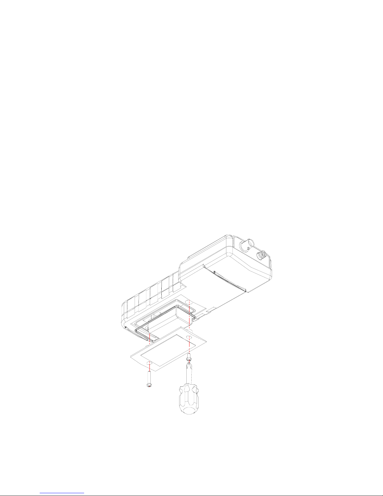
1. Use a screw driver to remove the two screw and battery cover to
expose the battery compartment. (Refer to Figure 1.)
2. Replace the 9V battery.
3. Replace the battery cover and make sure to fasten the two screws
for the water-tight feature.
Figure 1 Battery compartment
TURNING ON/OFF THE INSTRUMENT

6
Once the batteries are installed correctly you can press the
[ON/OFF] key to turn on or turn off the instrument. When the unit
is not in use the user should turn off the instrument to save battery
life..
ABOUT LCD DISPLAY
1. WAIT : This will be displayed if the unit is still waiting for a
stable
reading or end point sensing.
2. BAT : Low battery indicator.
3.ATC/MAN : ATC indicator will displayed if an ATC probe is
connected
otherwise the MAN indicator will be displayed.
4. STAND/SLOPE : This indicator will flash if the STAND or
SLOPE is
not yet calibrated respectively. This indicator will remain
lit-up
if the STAND or SLOPE is calibrated respectively.
Figure 2 LCD

7
5.AUTO : Autolock mode indicator.
6.HOLD : This will indicate that the reading is frozen during
autolock
mode.
7.EFF% : This will be displayed if the user is viewing the efficiency
of the
electrode.
8.pH/mV : Unit and mode indicators.
9.Main display for pH , mV and probe Efficiency values.
10.Temperature and unit display
KEY FUNCTIONS OF THE MODEL 6010
1.[ON/OFF] key. The [ON/OFF] key turns the instrument ON or
OFF.
The pH calibration values will not be erased when the instrument
is
turned off.
2. [MODE] key. The [MODE] key selects the parameters to be
displayed.
Pressing the [MODE] key changes the display sequentially to
display pH-
AUTOLOCK , mV-AUTOLOCK , pH and mV. The calibration
values
will not be affected by changing the display modes.
3.[STAND] and [SLOPE] keys. The [STAND] and [SLOPE] keys are
used for dual point pH calibration of the instrument.
a.Pressing and holding the [STAND] key while turning on the
power ,will chang the buffer set to the other available buffer set.
4.The [ ∆] and [ ∇] keys. The [ ∆] and [ ∇] keys are used to
manually

8
enter the temperature values. They have no effect on the
instrument
when operating in ATC mode.
5.[MEA./EFF.] key. a. The [MEA./EFF.] key is used to bring the
instrument out of the AUTOLOCK condition when operating in
the
pH-AUTOLOCK or mV-AUTOLOCK mode.
b.Press and hold this key for 5 seconds, the large LCD will
display the
efficiency of the electrode.
6.[CLEAR] key. The [CLEAR] key is used to clear the instrument
when
error signal appears. It clears all calibration values stored in the
internal
memory. To prevent accidental pressing the [CLEAR] key. Under
normal use the key will not be activated unless press and held for
2
seconds. The key will respond instantly only when error signal
appears.
When the [CLEAR] key is pressed, all segments of the LCD will
be on.
After about 2 seconds the instrument will enter the pH-
AUTOLOCK
mode. The AUTOLOCK annunciator will be on and the STAND
annunciator will start to flash. This means that the instrument
must be
calibrated. The [CLEAR] key is to be used only when errors are
made
that require the instrument to be re-calibrated.
OPERATIONAL PROCEDURES
BUFFER TABLE SELECT

9
There are two sets of buffer available for this unit : 7.00,4.01,10.01pH
and 6.86,4.00,9.18pH.
You can change the buffer set by turning OFF the unit then pressing
and holding the [STAND] key as you turn ON the unit again.
You can see what buffer set you are using if the unit is uncalibrated
and you are in pH mode. The unit will display 7.00 if you are using
the first set and 6.86 if you are using the second set.
pH CALIBRATION
Turn ON the instrument by pressing the [ON/OFF] key. The
instrument will be in a state when it was turned off. It is not
necessary to press the [CLEAR] key.
1. Calibration with an ATC/Temp probe in the pH-AUTOLOCK
mode.
1.1 Connect the combination pH electrode to the BNC
connector and
the ATC/Temp probe to into the ATC/Temp connector of
the
instrument. The ATC annunciator on the LCD will be on.
Press
the [MODE] key as necessary to go to pH-AUTOLOCK
mode.
1.2 Rinse the pH electrode and ATC/Temp probe in distilled
water
and immerse in pH buffer 7.00(or 6.86). The instrument will
display the buffer temperature.
1.3 Press the [STAND] key . The STAND annunciator will be
on and the WAIT annunciator will flash. At this time the
instrument is waiting for a stable reading. The display will
be locked to the buffer value corresponding to the
temperature of buffer 7.00 (or 6.86), as measured in step 1.2

10
(refer to table 1). When a stable reading is reached, the
WAIT annunciator will stop flashing and stay off. The
SLOPE annunciator will start to flash. This means that the
standardization at buffer 7.00 (or 6.86) has been completed
and the instrument is now ready to sloped at a second
buffer.
If "Er 1" is displayed, check that the correct buffer is used
and that the electrode offset is greater than - 1.5 pH and less
than +1.5 pH. Replace the buffer and/or the pH electrode.
Press the [CLEAR] key and repeat from 1.1. "Er 1" may
appear if the [STAND] key is pressed before the electrode
and ATC/Temp probe settle to within ±1.5 pH of the buffer
value. Allow sufficient time for the electrode and
ATC/Temp probe to stabilize before taking any actions.
If "Er 3" is displayed, the buffer temperature is out of the 0
to 60℃range. Bring the buffer temperature with in the
range . and repeat 1.2 It is not necessary to press the
[CLEAR] key.
1.4 Remove the pH electrode and ATC/Temp probe from
buffer 7.00 (or 6.86) and rinse both in distilled water. After
rinsing immerse both in buffer 4.01 or 9.18 or 10.01 pH.
1.5 Press the [SLOPE] key. The SLOPE annunciator will stop
flashing and stay on. The WAIT annunciator will start to
flash, indicating that the instrument is waiting for a stable
reading. The display will be locked to the second buffer
value corresponding to the temperature of the second buffer
(refer to table 1). When a stable reading is reached, the
WAIT annunciator will stop flashing and stay off. The
instrument will calculate and compensate for the pH
electrode slope deviation corresponding tot he values of the
two calibration buffers. The instrument is dual point
calibrated and is now ready for measurements.

11
After two point calibration, pressing and holding the
[MEA./EFF.]
key for about 5 seconds will display the new electrode
efficiency.
If "Er 2" is displayed, check that the correct buffer is used
and that the slope of the electrode is not off by more than
30% from the theoretical slope. Only buffers 4.01, 9.18 or
10.01 may be used for slope calibration. Replace the buffer
and/or the pH electrode. Press the [CLEAR] key and repeat
from 1.1. "Er 2" may appear if the [SLOPE] key is pressed
before the electrode and the ATC/Temp probe settle to
within 30% of the buffer value. Allow sufficient time for the
electrode and ATC/Temp probe to stabilize before taking
any action
If "Er 3" is displayed, the buffer temperature is out of the 0
to 60 ℃range. Bring the buffer temperature within the
range and repeat 1.2 It is not necessary to press the
[CLEAR] key.
2. Calibration with manual temperature compensation in the pH-
AUTOLOCK mode.
2.1 Connect the pH electrode to the top of the instrument. The
MAN annunciator will be on. Press the [MODE] key for the
LCD
to indicate pH and for the AUTO annunciator to be on .
2.2 Rinse the pH electrode in distilled water and immerse in
buffer
7.00 pH(or 6.86). Set the instrument to display the
temperature of the buffer by pressing the [ ∆] and [ ∇]
keys. The displayed temperature must be less than 60. ℃
2.3 Press the [STAND] key. the STAND annunciator will be on
and

12
the WAIT annunciator will flash. This means that the
instrument is waiting for a stable reading. The display will
be locked to the buffer value corresponding to the
temperature of buffer 7.00 (or 6.86) as set in 2.2 (refer to
table 1). When a stable reading is reached, the WAIT
annunciator will stop flashing and stay off. The SLOPE
annunciator will start to flash, indicating that the
standardization at buffer 7.00 (or 6.86) is completed and the
instrument is ready to be sloped at a second buffer.
If "Er 1" is displayed, check that the correct buffer is used
and that the electrode offset is greater than - 1.5 and less
than +1.5 pH. Replace the buffer and/or the pH electrode.
Press the [CLEAR] key and repeat from 2.1. "Er 1" may
appear if the [STAND] key is pressed before the electrode
and ATC/Temp probe settle to within ±1.5 pH of the buffer
value. Allow sufficient time for the electrode and
ATC/Temp probe to stabilize before taking any action.
2.4 Remove the pH electrode from buffer 7.00 (or 6.86), rinse
with distilled water and immerse in buffer 4.01 or 9.18 or
10.01. Set the instrument to the temperature of the 2nd
buffer as in 2.2. The displayed temperature must be greater
than 60. ℃
2.5 Press the [SLOPE] key. the SLOPE annunciator wills stop
flashing
and stay on. The WAIT annunciator will start to flash,
indicating that the instrument is waiting for a stable
reading. The display will be locked to the value of the
second buffer corresponding to the temperature of the
second buffer as set in 2.3 (refer to table 1). When a table
reading is reached, the WAIT annunciator will stop flashing
and stay off. The instrument will calculate and compensate
for the pH electrode slope deviation corresponding to the

13
values of the two calibration buffers. The instrument is dual
point calibrated and is now ready for measurements.
After two point calibration, pressing and holding the
[MEA./EFF.]
key for about 5 seconds will display the new electrode
efficiency.
If "Er 2" is displayed, check that the correct buffer is used
and that the slope of the electrode is not off by more than
30% from the theoretical slope. Only buffers 4.01, 9.18 or
10.01 may be used for slope calibration. Replace the buffer
and/or the pH electrode. Press the [CLEAR] key and repeat
from 2.1. "Er 2" may appear if the [SLOPE] key is pressed
before the electrode and the ATC/Temp probe settle to
within 30% of the buffer value. Allow sufficient time for the
electrode and ATC/Temp probe to stabilize before taking
any action
3. Calibration with ATC/Temp probe in pH mode.
3.1 Connect the pH electrode and the ATC/Temp probe to the
top of
the instrument. The ATC annunciator will be on. Press the
[MODE] key for the LCD to display pH and the
AUTOLOCK annunciator to be off.
3.2 Rinse the pH electrode and ATC/Temp probe in distilled
water
and immerse in pH buffer 7.00 (or 6.86). the instrument will
display the buffer temperature.
3.3 Allow sufficient time for the electrode and ATC/Temp
probe to stabilize. Press the [STAND] key. The STAND
annunciator will be on and the SLOPE annunciator will
flash, indicating that standardization at buffer 7.00 (or 6.86)

14
is completed and the instrument is ready to be sloped at a
second buffer. The instrument will display the buffer value
corresponding to the temperature of the buffer 7.00 (or 6.86)
as measured in 3.2 (refer to table 1). If the reading still drifts,
repeat 3.3 until a stable reading is obtained.
If "Er 1" is displayed, check that the correct buffer is used
and that the electrode offset is greater than - 1.5 and less
than +1.5 pH. Replace the buffer and/or the pH electrode.
Press the [CLEAR] key and repeat from 3.1. "Er 1" may
appear if the [STAND] key is pressed before the electrode
and ATC/Temp probe settle to within ±1.5 pH of the buffer
value. Allow sufficient time for the electrode and
ATC/Temp probe to stabilize before taking any action.
If "Er 3" is displayed, the buffer temperature is out of the 0
to 60℃range. Bring the buffer temperature with in the
range . and repeat 3.2 It is not necessary to press the
[CLEAR] key.
3.4 Remove the pH electrode and ATC/Temp probe from
buffer 7.00
(or 6.86). Rinse them in distilled water and immerse in
buffer 4.01 or 9.18 or 10.01. The instrument will display the
temperature of the second buffer.
3.5 Allow sufficient time for the pH electrode and ATC/Temp
probe
to stabilize. Press the [SLOPE] key. The SLOPE annunciator
will stop flashing and stay on. The instrument will display
the second buffer value corresponding to the temperature of
the second buffer, as measured in 3.4 (refer to table 1). If the
reading still drifts, repeat 3.5, until a stable reading is
obtained. The instrument will calculate and compensate for
the pH electrode slope deviation corresponding to the

15
values of the two calibration buffers. The instrument is dual
point calibrated and is now ready for measurements.
After two point calibration, pressing and holding the
[MEA./EFF.] key for about 5 seconds will display the new
electrode efficiency.
If "Er 2" is displayed, check that the correct buffer is used
and that the slope of the electrode is not off by more than
30% from the theoretical slope. Only buffers 4.01, 9.18 or
10.01 may be used for slope calibration. Replace the buffer
and/or the pH electrode. Press the [CLEAR] key and repeat
from 1.1. "Er 2" may appear if the [SLOPE] key is pressed
before the electrode and the ATC/Temp probe settle to
within 30% of the buffer value. Allow sufficient time for the
electrode and ATC/Temp probe to stabilize before taking
any action
If "Er 3" is displayed, the buffer temperature is out of the 0
to 60℃rang. Bring the buffer temperature within the range
and repeat 1.2 It is not necessary to press the [CLEAR] key.
4. Calibration with manual temperature compensation in the pH
mode.
4.1 Connect the pH electrode to the top of the instrument (refer
to figure 1). The MAN annunciator will be on. Press the
[MODE] key for the LCD to indicate pH and for the AUTO
annunciator to be on.
4.2 Rinse the pH electrode in distilled water and immerse in
buffer 7.00 (or 6.86). Set the instrument to display the
temperature of the buffer by pressing the [ ∆] and [ ∇]
keys. The displayed temperature must be less than 60℃.
4.3 Allow sufficient time for the electrode to stabilize. Press the

16
[STAND] key. the STAND annunciator will be on and the
SLOPE annunciator will start to flash, indicating that the
standardization at buffer 7.00 (or 6.86) is completed and the
instrument is ready to be sloped at a second buffer. The
instrument will display the buffer value corresponding to
the temperature of the buffer 7.00 (or 6.86) set in 4.2 (refer to
table 1). If the reading still drifts, repeat 4.3 until a stable
reading is obtained.
If "Er 1" is displayed, check that the correct buffer is used
and that the electrode offset is greater than - 1.5 pH and less
than +1.5 pH. Replace the buffer and/or the pH electrode.
Press the [CLEAR] key and repeat from 4.1. "Er 1" may
appear if the [STAND] key is pressed before the electrode
and ATC/Temp probe settle to within ±1.5 pH of the buffer
value. Allow sufficient time for the electrode and
ATC/Temp probe to stabilize before taking any action.
4.4 Remove the pH electrode from buffer 7.00 (or 6.86), rinse
with
distilled water and immerse it in buffer 4.01 or 9.18 or 10.01.
Set the instrument to the temperature of the 2nd buffer as in
4.2. The displayed temperature must be greater than 60. ℃
4.5 Allow sufficient time for the pH electrode to stabilize. Press
the [SLOPE] key. the SLOPE annunciator wills stop flashing
and stay on. The instrument will display the value of the
second buffer corresponding to the temperature of the
second buffer as set in 4.4 (refer to table 1). If the reading
still drifts, repeat 4.5, until a stable reading is obtained. The
instrument will calculate and compensate for the pH
electrode slope deviation corresponding to the values of the
two calibration buffers. The instrument is dual point
calibrated and is now ready for measurements.

17
After two point calibration, pressing and holding the
[MEA./EFF.]
key for about 5 seconds will display the new electrode
efficiency.
If "Er 2" is displayed, check that the correct buffer is used
and that the slope of the electrode is not off by more than
30% from the theoretical slope. Only buffers 4.01, 9.18 or
10.01 may be used for slope calibration. Replace the buffer
and/or the pH electrode. Press the [CLEAR] key and repeat
from 4.1. "Er 2" may appear if the [SLOPE] key is pressed
before the electrode settles to within 30% of the buffer
value. Allow sufficient time for the electrode to stabilize
before taking any action
pH MEASUREMENTS
The STAND and SLOPE annunciators must be on. This means that
the instrument is dual point calibrated and is ready for
measurements.
1. Measurement with ATC/Temp probe in the pH-AUTOLOCK
mode.
1.1 Connect the pH electrode and ATC/Temp probe to the top
of the
instrument . The ATC annunciator will be on.
1.2 Press the [MODE] key until the LCD indicates pH mode
and the
AUTO annunciator is on.
1.3 Rinse the pH electrode and the ATC/Temp probe with
distilled
water and immerse them in the sample to be measured.

18
1.4 Press the measure key. The WAIT annunciator will start
flashing.
This means the instrument is waiting for a stable reading.
The pH will track the pH value as sensed by the pH
electrode and the ATC/Temp probe. When the display
changes less than 0.01 pH in about 10 seconds the autolock
function will be activated. The WAIT annunciator will stop
flashing and stay off. The reading is then "locked" and will
not respond to further changes from the pH electrode and
ATC/Temp probe. The "locked" display is the pH value of
the sample at the displayed sample temperature.
If "OvEr/Undr" is displayed, the pH value measured is out
of the
“16.00/-2.00 pH “ range.
1.5 For samples that are inherently unstable, the instrument
will not
AUTOLOCK. In this case, use the pH NON-AUTOLOCK
mode for measurements.
2. Measurement with ATC/Temp probe in the pH NON-
AUTOLOCK
mode.
2.1 Connect the pH electrode and the ATC/Temp probe to the
top of
the instrument. The ATC annunciator will be on .
2.2 Press the [MODE] key for the LCD to indicate pH and for
the
AUTO annunciator to be off.
2.3 Rinse the pH electrode and the ATC/Temp probe with
distilled
water and immerse them in the sample to measured.

19
2.4 Allow sufficient time for the display to stabilize. The
instrument
will display the pH value of the sample at the displayed
sample temperature.
If "OvEr/Undr" is displayed, the pH value measured is out
of the
“16.00/-2.00 pH” range.
3. Measurement with manual temperature compensation in the
pH-AUTOLOCK mode.
3.1 Connect the pH electrode to the top of the instrument. The
MAN annunciator will be on.
3.2 Press the [MODE] key for the LCD to indicate pH and for
the
AUTO annunciator to be on.
3.3 Rinse the pH electrode with distilled water and immerse it
in the
sample to be measured. Set the instrument to the
temperature of the sample as in 2.2 of pH CALIBRATION
section.
3.4 Press the [MEA/EFF.] key. the WAIT annunciator will start
to
flash. This means that the instrument is waiting for a stable
reading. The display will track the pH value as sensed by
the pH
electrode. When the display changes less than 0.01 pH
within
approximately 10 seconds, the autolock function will be
activated.
The WAIT annunciator will stop flashing and stay off. The
reading

20
is then "locked" and will not respond to further changes
from the
pH electrode. The "locked" display is the pH value of the
sample at
the set sample temperature.
If "OvEr/Undr" is displayed, the pH value measured is out
of the
“16.00/-2.00 pH” range.
3.5 For samples that are inherently unstable, the instrument
will not autolock. Use the pH NON-AUTOLOCK mode for
measurements.
4.Measurement with manual temperature compensation in the pH
NON- AUTOLOCK mode.
4.1 Connect the pH electrode to the top of the instrument.
4.2 Press the [MODE] key for the LCD to display pH and for
the
AUTO annunciator to be off.
4.3 Rinse the pH electrode with distilled water and immerse it
in the
sample to be measured.
4.4 Set the instrument to the temperature of the sample as 2.2 of
pH
CALIBRATION section.
4.5 Allow sufficient time for the display to stabilize. The
instrument
Will display the pH value of the sample at the set sample
temperature.
If "OvEr/Undr" is displayed, the pH value measured is out
of the
Table of contents
Other JENCO Measuring Instrument manuals

JENCO
JENCO VisionPlus 6377B User manual

JENCO
JENCO VisionPlus pH618N User manual

JENCO
JENCO 6011B User manual

JENCO
JENCO 3175-307A User manual

JENCO
JENCO EC3840 User manual

JENCO
JENCO 6010N User manual

JENCO
JENCO 3321 User manual

JENCO
JENCO pH619 Installation manual

JENCO
JENCO 6177M User manual

JENCO
JENCO pH610N User manual

JENCO
JENCO VisionPlus 9020M User manual

JENCO
JENCO 6360 User manual

JENCO
JENCO 6010M User manual

JENCO
JENCO VisionPlus pH6810 User manual

JENCO
JENCO 6377MB User manual

JENCO
JENCO 6230M User manual

JENCO
JENCO 6250 User manual

JENCO
JENCO VisionPlus pH6175 User manual

JENCO
JENCO 6177B User manual

JENCO
JENCO VisionPlus pH630FA User manual


