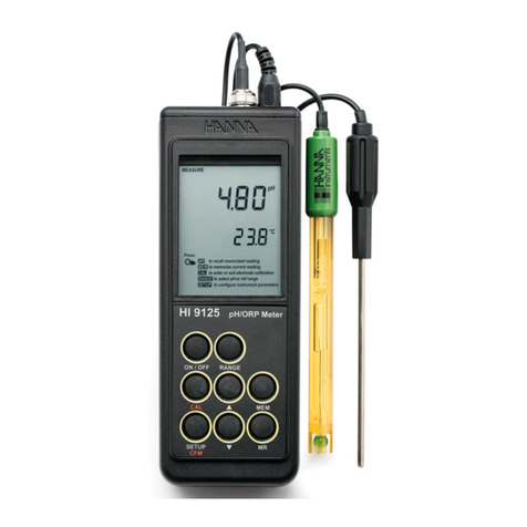
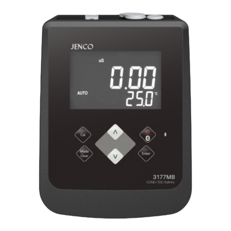
JENCO 6179MB User manual

Operation Manual
MODEL 6179MB
pH/ORP/ION/Temperature
Based Bluetooth Benchtop Meter
6179MB

1
CONTENTS
GENERAL INTRODUCTION.........................................2
INITIAL INSPECTION....................................................2
POWER INPUT..............................................................3
INSTALLING THE BATTERIES....................................3
CONNECTORS..............................................................4
DISPLAY & KEYS FUNCTIONS...............................................4
A. Display..............................................................................4
B. Operational Keys Description...................................5
OPERATIONAL PROCEDURES...................................7
A. Buffer Set Selection.................................................7
B. pH Calibration..........................................................7
C. pH Measurements...................................................11
D. Temperature Measurements....................................12
E. mV offset...............................................................12
F. mV (Rmv) Measurements.........................................13
G. Ion Calibration........................................................14
H. Ion Measurements..................................................16
I. Ion Selective Electrodes..........................................17
J. Save, Recall and Delete Data....................................17
K.pH Buffers .............................................................19
APP NAVIGATION.......................................................19
FCC WARNING STATEMENT......................................24
ERROR DISPLAYS AND TROUBLESHOOTING.......25
SPECIFICATIONS.......................................................26
WARRANTY................................................................27

2
GENERAL INTRODUCTION
Thank you for selecting the 6179MB meter. The 6179MB is a
precision tool that measures pH, mV, ion concentration and
temperature. A built-in microprocessor stores, calculates and
compensates for all parameters related to pH determinations
including pH electrode temperature characteristics, electrode slope
deviations, offset and buffer solutions. The 6179MB is a 5th
generation pH/ORP/ION/temperature Bluetooth benchtop meter
with iOS and Android tablet connectivity.
This meter has a waterproof IP54 case. The mechanical keys are
highly reliable with tactile and audio feedback. It is powered by six
AAA-size alkaline batteries or with a UL/CE approved AC adapter
(OUTPUT:DC 9 V). The meter also displays a “BAT” message when
the batteries are in need of replacement. Re-calibration is not
required when power is restored.
The front of the meter has a large LCD that displays pH , mV , Rmv,
ion and temperature measurements along with user prompts and
mode indicators. The unit prompts the user through calibration and
measurement procedures.
An AUTOLOCK feature for pH, mV (RmV) and ion measurements
enables the unit to automatically sense the end point and “LOCK”
the display to indicate the end point value of a measurement.
AUTOLOCK and user prompts help eliminate most errors in
determining pH, mV (Rmv), ion values, resulting in precise,
repeatable and error-free measurements. The 6179MB can also be
used in non-AUTOLOCK mode.
The unit is also equipped with a non-volatile memory allowing the
user to store 750 different sets of readings. This unit will assign a
site number for each set of reading so the user can review the data
easily.
The model 6179MB is available with pH, ORP, ion and ATC
(Automatic Temperature Compensation) probes. Other features
include up to 5 point calibration for pH , 2 to 5 point calibration for
ion, 1 point calibration for ORP, electrode offset recognition,
electrode slope recognition, electrode efficiency display, built-in
buffer coefficients, automatic or manual temperature compensation
and 50/60 Hz AC noise rejection. This meter is user-friendly for
laboratory application.
INITIAL INSPECTION
Carefully unpack the unit and accessories. Inspect for damages
made in shipment. If any damage is found, notify your JENCO
representative immediately. All packing materials should be saved

3
until satisfactory operation is confirmed.
POWER INPUT
The model 6179MB can be powered by an UL/CE approved 100 to
240 V AC adaptor as well as 6 “AAA” alkaline batteries. Check the
label on the AC adaptor supplied with the instrument to make sure
that the AC line voltage is correct. If the wrong AC adaptor is
supplied, notify your JENCO representative immediately.
INSTALLING THE BATTERIES
To insert the batteries into the meter, follow the procedure outlined
below.
1. Use a Philip screw driver and unlock the battery cover by
turning the screw driver in the counter clockwise direction.
After unlocking the screw, take off the battery cover (Fig.1)
2. Replace the old batteries with new ones and install them in the
correct polarity position.
3. Put the battery cover back on the instrument. Use a Philip
screw driver and turn the screw in the clockwise direction to
lock the battery cover.
Figure 1: Battery compartment

4
CONNECTORS
1 2 3
Figure 2: Connector
1. pH/ORP/ISE connector (BNC connector)
2. ATC connector (8 PIN connector)
3. AC adaptor input connector
DISPLAY & KEYS FUNCTIONS
A. Display
1
2
3
4
5
6
7
9
10
12
11
81.68 4.01 7.00 10.01
4.00 6.86 9.18 12.46
Figure 3: Active LCD screen
1. WAIT-
This will be displayed when
the unit is still waiting for a
stable reading or end point
sensing.
7. AUTO-
AUTOLOCK mode indicator.
2. BAT-
Low battery indicator.
8. Buffer selection-
This indicator will flash if the
unit is not yet calibrated.
This indicator will remain
lit-up if the unit has been
calibrated.

5
3. pH-
Unit and mode indicators.
9. LOCK-
This will indicate that the
reading is frozen during
AUTOLOCK mode.
4. mV (RmV)-
Unit and mode indicators.
10.EFF-
This will be displayed if the
user is viewing the
efficiency of the electrode.
5. ATC/MAN-
ATC indicator will be
displayed if a temperature
probe is connected
otherwise the MAN indicator
will be displayed.
11.MAIN DISPLAY-
For pH, mV (RmV), ion and
probe efficiency values
6. CAL-
This will be displayed when
the unit enters into the
calibration mode.
12.SECONDARY DISPLAY-
For temperature in ℃.
B. Operational Keys Description
Figure 4
NO. Key Description
1
Stand
Stand & Slope/Enter-
These two keys are used for pH, ORP and ion
calibration. For their specific functions, please see
the "calibration" section in each parameter.
In the measure mode, press “Slope/Enter” key
for 2 seconds to save reading into the data
storage site.
At the Recall interface, press “Slope/Enter” key
to display the last set of saved data.
In the “Delete All” mode, press “Slope/Enter” and
enters the selection screen.
In the “Delete One” mode, press “Slope/Enter”
key to delete a single set of data.
Slope
Enter

6
2
Mode-
Selects display mode. Pressing this key changes
the display sequentially to display
pH-AUTOLOCK, mV (RmV)-AUTOLOCK,
ION-AUTOLOCK, pH , mV (RmV), ion, Recall,
Delete One and Delete ALL. The calibration
values will not be affected by changing the display
modes.
In the calibration mode, press “Mode” key to exit
calibration mode.
In “Recall” and “Delete” modes, press “Mode” key
to exit “Recall” and “Delete” modes respectively.
3
Set/Clear-
In the measure mode, when the “Set/Clear” key
is pressed for 5 seconds, all segments of the LCD
will be on. The meter clears all calibration values
stored in internal memory.
In the pH mode, press the “Set/Clear” key to
enter the buffer set selection screen.
In the ion mode, press the “Set/Clear” key to
enter the calibration point selection mode.
4
Power/BLE (Bluetooth)-
Press and hold this key for 2 seconds to power on
and shut off the meter.
In the measure mode, press this key to turn
Bluetooth on or off.
5
Mea.
Eff.
Stand
Slope
Mode
Clear
Mea./Eff.-
This key is used to bring the unit out of the
AUTOLOCK condition when operating in the
pH-AUTOLOCK, mV (RmV)-AUTOLOCK or
ion-AUTOLOCK mode.
In the pH or ion measure mode, press and hold
this key for 5 seconds, the LCD will display the
efficiency of the electrode and the offset value.
In the ORP measure mode, press and hold this
key for 5 seconds, the LCD will display the offset
value of the electrode.
6
Mea.
Eff.
Stand
Slope
Mode
Clear
Mea.
Eff.
Stand
Slope
Mode
Clear
Up & Down-
In the pH/ORP/ION measure mode, these two
keys are used to manually enter the temperature
values. They have no effect on the unit when
operating in ATC mode.
In the ORP calibration mode, these two keys are
used to adjust the RmV display value.
In the “Set” mode, these two keys are used to
choose the corresponding settings.
In the “Recall” mode, view saved data and data
storage site number by pressing these keys.
In the “Delete One” mode, view to be deleted data
and data site numbers by pressing these keys.

7
OPERATIONAL PROCEDURES
A. pH Buffer Set Selection
The 6179MB meter has two buffer sets: 1.68, 7.00, 4.01, 10.01,
12.46 pH and 1.68, 6.86, 4.00, 9.18, 12.46 pH.
In pH mode, press “Set/Clear” key to enter the buffer set
selection mode. Use “Up” or “Down” key to select the
preferred buffer set. Press “Slope/Enter” key to save the
selected buffer set.
[Note: There is no need to repeat this procedure every time the
unit is power up unless one decides to change the buffer
settings.]
B. pH Calibration
The 6179MB uses up to 5 point calibration.
[Note: If the device is required to perform more than one
calibration points, the first calibration point must be 6.86/7.00
pH.]
1. Calibration with an ATC/Temp probe in the pH-AUTOLOCK
mode.
a. Turn the unit on. In the pH mode, press “Set/Clear” key
for 5 seconds, all LCD elements will lit up. The meter
clears all calibration values stored in internal memory.
b. Connect the pH electrode to the BNC connector and the
ATC/Temp probe to the ATC/Temp connector of the unit.
c. Press “Mode” key to go to pH-AUTOLOCK mode. “ATC”
icon, “pH” icon and “AUTO” icon will lit up. The "CAL" icon
begins to flash.
d. Rinse the pH and ATC/Temp probes in distilled water and
immerse them in the first buffer solution. Allow
temperature reading to stabilize, then press and hold
“Stand” key for 2 seconds to calibrate. The“WAIT”icon
will flash until the unit detects a stable reading. Once the
unit calibrates the first point, the selected buffer will lit up
while two other selectable buffers start to flash. The unit is
ready to be sloped at the second buffer if the first buffer
solution is 6.86 or 7.00 pH.
[Note: At this moment, press the “Mode” key, the unit will
exit the calibration mode. Single point calibration is
complete.

8
To continue with two or more point calibration, the first
buffer solution has to be either 7.00 or 6.86 pH.]
e. Rinse the pH and ATC/Temp probe in distilled water and
immerse them in the second buffer solution (either 4.00 /
4.01 pH or 9.18 / 10.01 pH corresponding to the flashing
number on display). Allow temperature reading to stabilize,
then press “Slope/Enter” key to calibrate. The “WAIT”
icon will flash until the unit detects a stable reading. Once
the unit calibrates the second point, the selected two
buffers lit up and the remaining buffer starts to flash. The
unit is ready to be sloped at the third buffer.
[Note: At this moment, press the “Mode” key, the unit
will exit the calibration mode. Dual point calibration is
complete.]
f. The procedure to calibrate the third point, the fourth point
and the fifth point are the same as the second calibration
point. When the unit completed the fifth point calibration,
press the “Mode” key and exit calibration mode.
g. The unit calculates and compensates for the pH electrode
slope deviation corresponding to the values of the
calibrated buffers. After calibration, press and hold
“Mea./Eff.” key for about 5 seconds to display the new
electrode efficiency and offset value.
2. Calibration with manual temperature compensation in the
pH-AUTO LOCK mode.
a. Turn the unit on. In the pH mode, press “Slope/Enter” key
to save the selected buffer set. Press “Set/Clear” key for
5 seconds, all LCD elements will lit up. The meter clears
all calibration values stored in internal memory.
b. Connect the pH electrode to the BNC connector of the
unit.
c. Press “Mode” key to go to pH-AUTOLOCK mode. “MAN”
icon, “pH” icon and “AUTO” icon will lit up. The "CAL" icon
begins to flash.
d. Rinse the pH probes in distilled water and immerse it in the
first buffer solution. Adjust the temperature reading to that
of the first buffer using the “Up” or “Down” key (0.0 to
60.0 ℃). Then press and hold “Stand” key for 2 seconds
to calibrate. The “WAIT” icon will flash until the unit detects
a stable reading. Once the unit calibrates the first point,
the selected buffer remains lit up while two other
selectable buffers start to flash. The unit is ready to be

9
sloped at the second buffer if the first buffer solution is
6.86 or 7.00 pH.
[Note: At this moment, press the “Mode” key, the unit will
exit the calibration mode. Single point calibration is
complete.
To continue with two or more point calibration, the first
buffer solution has to be either 7.00 or 6.86 pH.]
e. Repeat steps “e” of “Calibration with an ATC/Temp
probe in the pH-AUTOLOCK mode” for 2 to 5 point
calibration.
f. The unit calculates and compensates for the pH electrode
slope deviation corresponding to the values of the
calibrated buffers. After calibration, press and hold
“Mea./Eff.” key for about 5 seconds to display the new
electrode efficiency and offset value.
3. Calibration with an ATC/Temp probe in the pH NON-
AUTOLOCK mode.
a. Turn the unit on. In pH mode, press “Set/Clear” key for 5
seconds, all LCD elements will lit up. The meter clears all
calibration values stored in internal memory.
b. Connect the pH electrode to the BNC connector and the
ATC/Temp probe to the ATC/Temp connector of the unit.
c. Press “Mode” key for the LCD to display pH and the
AUTOLOCK annunciator is off. “ATC” icon will lit up, “pH”
icon is on. The "CAL" icon will begin to flash.
d. Rinse the pH and ATC/Temp probes in distilled water and
immerse them in the first buffer solution. Allow
temperature reading to stabilize. Then press and hold
“Stand” key for 2 seconds to calibrate, the unit
immediately calibrates the first point, the selected buffer
remains lit up while two other selectable buffers start to
flash. The unit is ready to be sloped at the second buffer if
the first buffer solution is 6.86 or 7.00 pH.
[Note: At this moment, press the “Mode” key, the unit will
exit the calibration mode. Single point calibration is
complete.
To continue with two or more point calibration, the first
buffer solution has to be either 7.00 or 6.86 pH.]
e. Rinse the pH and ATC/Temp probe in distilled water and
immerse them in the second buffer solution (either
4.00/4.01 pH or 9.18/10.01 pH corresponding to the

10
flashing number on display). Allow temperature reading to
stabilize, then press “Slope/Enter” key to calibrate. The
unit immediately calibrates the second point, the selected
two buffers lit up and the remaining buffer starts to flash.
The unit is ready to be sloped at the third buffer.
[Note: At this moment, press the “Mode” key, the unit
will exit the calibration mode. Dual point calibration is
complete.]
f. The procedure to calibrate the third point, the fourth point
and the fifth point are the same as the second point
calibration. When the unit completed the fifth calibration
point, press the “Mode” key and exit calibration mode.
g. The unit calculates and compensates for the pH electrode
slope deviation corresponding to the values of the
calibrated buffers. After calibration, press and hold
“Mea./Eff.” key for about 5 seconds to display the new
electrode efficiency and offset value.
4. Calibration with manual temperature compensation in the
pH NON-AUTOLOCK mode.
a. Turn the unit on. In pH-NON-AUTOLOCK mode, press
“Set/Clear” key for 5 seconds, all LCD elements will lit up.
The meter clears all calibration values stored in internal
memory.
b. Connect the pH electrode to the BNC connector of the
unit.
c. Press “Mode” key for the LCD to display pH and the
AUTOLOCK annunciator is off. “MAN” icon will lit up, “pH”
icon is on. The "CAL" icon will begin to flash.
d. Rinse the pH electrode in distilled water and immerse it in
the first buffer solution. Adjust the temperature reading to
that of the first buffer using the “Up” or “Down” key (0.0 to
60.0 ℃) before pressing “Stand” key. Then press and
hold “Stand” key for 2 seconds to calibrate. The unit
immediately calibrates the first point. The selected buffer
remains lit up while the remaining buffers start to flash.
The unit is ready to be sloped at the second buffer if the
first buffer solution is 6.86 or 7.00 pH.
[Note: At this moment, press the“Mode” key, the unit will
exit the calibration mode. Single point calibration is
complete.
To continue with two or more point calibration, the first
buffer solution has to be either 7.00 or 6.86 pH.]

11
e. Repeat steps “e” of “Calibration with an ATC/Temp
probe in the pH NON- AUTOLOCK mode” for 2 to 5
point calibration.
f. The unit calculates and compensates for the pH electrode
slope deviation corresponding to the values of the
calibrated buffers. After calibration, press and hold
“Mea./Eff.” key for about 5 seconds to display the new
electrode efficiency and offset value.
C. pH Measurements
To take pH measurements, 6179MB must be calibrated before
first use.
1. Measurement with an ATC/Temp probe in the pH-
AUTOLOCK mode.
a. Connect the pH electrode to the BNC connector and the
ATC/Temp probe to the ATC/Temp connector of the meter.
The “ATC” icon will lit up.
b. Press “Mode” key until “pH”, “AUTO”, “ATC”, “buffer”
icons lit up. The “WAIT” icon will begin to flash.
c. Rinse the pH electrode and ATC/Temp probe with distilled
water and immerse in the sample to be measured. Remove
any air bubbles trapped around the probe by shaking or
stirring the probe.
d. Press the “Mea./Eff.” key. The “WAIT” icon will start
flashing. The unit is waiting for a stable reading. The
display will track the pH value as sensed by the pH
electrode and the ATC/Temp probe.
e. When the “WAIT” icon disappears, the reading is then
“LOCK” and will not respond to further changes from the
sample. The pH value shown is the pH value of the sample
at the displayed sample temperature.
[Note: For samples that are inherently unstable, the unit
will not AUTOLOCK. In this case, use the pH NON-
AUTOLOCK mode for measurements.]
2. Measurement with manual temperature compensation in
the pH-AUTOLOCK mode.
a. Connect the pH electrode to the BNC connector of the
meter. The “MAN” icon will lit up. Set unit to display the
sample temperature by pressing “Up” or “Down” key
(-10.0 to 120.0 ℃).

12
b. Press the “Mode” key until “pH”, “AUTO”, “MAN”, “buffer”,
icons lit up. The “WAIT” icon will begin to flash.
c. Repeat steps “c” to “e” of “Measurement with an
ATC/Temp probe in the pH- AUTOLOCK mode”.
3. Measurement with an ATC/Temp probe in the pH NON-
AUTOLOCK mode.
a. Connect the pH electrode to the BNC connector and the
ATC/Temp probe to the ATC/Temp connector of the meter.
The “ATC” icon will lit up.
b. Press the “Mode” key until “pH”, “ATC”,“buffer” icons lit
up.
c. Rinse the pH electrode and ATC/Temp probe with distilled
water and immerse in the sample to be measured. Remove
any air bubbles trapped around the probe by shaking or
stirring the probe.
d. Allow sufficient time for the display to stabilize. The meter
will display the pH value of the sample at the displayed
sample temperature.
4. Measurement with manual temperature compensation in
the pH NON-AUTOLOCK mode.
a. Connect the pH electrode to the BNC connector of the
unit. The “MAN” icon will lit up. Set unit to display the
sample temperature by pressing the “Up” or “Down” key
(-10.0 to 120.0 ℃).
b. Press “Mode” key until “pH”, “MAN”, “buffer” icons lit up.
c. Repeat steps “c” and “d” of “Measurement with an
ATC/Temp probe in the pH NON- AUTOLOCK mode”.
D. Temperature Measure
The 6179MB can measure temperature independently with the
ATC/Temp probe without using the pH electrode. Place the
ATC/Temp probe in the sample. The unit will display the
measured temperature.
E. mV Offset
1. Turn the unit on. In mV mode, press “Set/Clear” key for 5
seconds, all LCD elements will lit up. The meter clears all
calibration values stored in internal memory.

13
2. Connect the ORP electrode to the BNC connector of the unit.
3. Press “Mode” key for the LCD to display “MAN”, “mV” and
“AUTO” icons will lit up. The "WAIT" icon begins to flash.
4. Rinse the ORP probe in distilled water and immerse it in the
standard solution. Then press and hold “Stand” key for 2
seconds to calibrate. The “CAL” , “RmV” and “MAN” icons
will lit up. According to the mV (RmV) value displayed, press
the “Up” or “Down” key to adjust the display value to the
same value as the standard solution. Press the
“Slope/Enter” key to save and complete the calibration.
5. Press and hold “Mea./Eff.” key for about 5 seconds to
display the new electrode offset value.
F. mV (RmV) Measurements
1. Measurement in the mV (RmV)-AUTOLOCK mode.
a. Connect the optional combination ORP electrode to the
BNC connector of the unit.
b. Press “Mode” key until “mV” or “RmV” icon, “MAN”,
“AUTO” icons lit up. The "WAIT" icon begins to flash.
c. Rinse the ORP electrode with distilled water and immerse it
in sample to be measured. Remove any air bubbles
trapped around the electrode by shaking or stirring the
electrode.
d. Press the “Mea./Eff.” key. The “WAIT” icon will start
flashing. The unit is waiting for a stable reading. The
display will track the mV (RmV) value as sensed by the
ORP electrode.
e. When the “WAIT” icon disappears and the “LOCK” icon
appears, the meter will not respond to further changes from
the sample. The mV (RmV) value is the sample reading
[Note: For samples that are inherently unstable, the unit
will not AUTOLOCK. In this case, use the mV (RmV)
NON- AUTOLOCK mode for measurements.]
2. Measurement in the mV (RmV) NON-AUTOLOCK mode.
a. Connect the optional combination ORP electrode to the
BNC connector of the unit.
b. Press the “Mode” key until “mV” or “RmV” and “MAN”

14
icons lit up.
c. Rinse the ORP electrode with distilled water and immerse
it in sample to be measured. Remove any air bubbles
trapped around the electrode by shaking or stirring the
electrode.
d. Allow sufficient time for the display to stabilize. The meter
will display the mV (RmV) value of the sample.
G. ION Calibration
The 6179MB can measure ion concentration when using an
ion selective electrode (ISE) for the specific ion of interest. The
available ion calibration values are 0.10, 1.0, 10.0, 100.0, and
1000. Choose a minimum of 2 consecutive values for
calibration and prepare the corresponding ion calibration
solutions. For best results always begin with the lowest
standard value, followed by the next lowest standard. The
6179MB uses 2 to 5 point calibration.
1. Calibration in the ION-AUTOLOCK mode.
a. Turn the unit on. In ION-AUTOLOCK mode, press
“Set/Clear” key for 5 seconds, all LCD elements will lit up.
The meter clears all calibration values stored in internal
memory.
b. Press the “Set/Clear” key to enter the calibration point
selection screen. Using the “Up” or “Down” key to select 2
to 5 point calibration.
c. Press “Slope/Enter” key to enter the monovalent
ion/divalent ion selection screen. Using the “Up” or
“Down” key to select. Press “Slope/Enter” key to save.
d. Connect the ISE to the BNC connector of the unit.
e. Press the “Mode” key for the LCD to display “MAN” and
“AUTO” icons will lit up. The "CAL" icon will begin to flash.
f. Rinse the ISE in distilled water and immerse it in the first
standard solution. Press and hold “Stand” key for 2
seconds to calibrate. The “CAL” & “AUTO” icons will lit up.
The main display will show “- - - -”, the secondary display
will show corresponding ion calibration value (0.10, 1.0, 10,
100). Using the “Up” or “Down” key to select the first point
calibration value. Press “Slope/Enter” key to save.
g. Press “Slope/Enter” key. The mV value of the standard

15
solution will appear on the main display. The “Wait” icon will
flash until the meter detects a stable value. When the
“Wait” icon disappears and the ion calibration value on the
secondary screen moves up to the next value, the first point
calibration is complete and the meter is ready for the
second point calibration.
h. Rinse the ISE in distilled water and immerse it in the second
standard solution. Press “Slope/Enter” key. The “Wait”
icon will flash until the meter detects a stable reading.
When the “Wait” icon disappears and the ion calibration
value on the secondary screen moves up to the next value,
the second point calibration is complete and the meter is
ready for the third point calibration.
i. To continue with the third, the fourth and the fifth point
calibration, repeat step “g”. Press “Mode” key to exit
calibration mode when the desired calibration points are
completed.
[Note: The slope (mV difference between two consecutive
points) is 15 to 90 mV.]
2. Calibration in the ION-NON-AUTOLOCK mode.
a. Turn the unit on. In ION-NON-AUTOLOCK mode, press
“Set/Clear” key for 5 seconds, all LCD elements will lit up.
The meter clears all calibration values stored in internal
memory.
b. Press the “Set/Clear” key to enter the calibration point
selection screen. Use “Up” or “Down” key to select 2 to 5
point calibration.
c. Press “Slope/Enter” key to enter the monovalent
ion/divalent ion selection screen. Using the “Up” or
“Down” key to select. Press “Slope/Enter” key to save.
d. Connect the ISE to the BNC connector of the unit.
e. Press “Mode” key for the LCD to display “MAN” icon will lit
up. The "CAL" icon will begin to flash.
f. Rinse the ISE in distilled water and immerse it in the first
standard solution. Press and hold “Stand” key for 2
seconds to calibrate. The “CAL” icon will lit up. The main
display will show “- - - -”, the secondary display will show
corresponding ion calibration value (0.10, 1.0, 10, 100).
Using the “Up” or “Down” key to select the first point
calibration value. Press “Slope/Enter” key to save.

16
g. Press “Slope/Enter” key. The mV value of the standard
solution. When the mV value of the standard solution is
stable, press “Slope/Enter" key to save. The ion
calibration value on the secondary screen moves up to the
next value. The first point calibration is complete and the
meter is ready for the second point calibration.
h. Rinse the ISE in distilled water and immerse it in the second
standard solution. When the mV value of the standard
solution is stable, press “Slope/Enter" key to save. The
ion calibration value on the secondary screen moves up to
the next value. The second point calibration is complete
and the meter is ready for the third point calibration.
[Note: At this moment, press the “Mode” key, the unit will
exit the calibration mode. Double point calibration is
complete. ]
i. To continue with the third, the fourth and the fifth point
calibration, repeat step “h”. Press “Mode” key to exit
calibration mode when the desired calibration points are
completed.
[Note: The slope (mV difference between two consecutive
points) is 15 to 90 mV.]
H. ION Measurements
1. Measurement in the ION-AUTOLOCK mode.
a. Connect the ISE to the BNC connector of the meter.
b. Press “Mode” key until “AUTO” and “MAN” icons lit up.
c. Rinse the ISE with distilled water and immerse it in sample
to be measured.
d. Press the “Mea./Eff.” key. The “WAIT” icon will start to
flash. The unit is waiting for a stable reading. The display
will track the ion value as sensed by the ion selective
electrode.
e. When the “WAIT” icon disappears, the reading is then
“LOCK” and will not respond to further changes from the
sample. The ion value is the sample reading.
[Note: For samples that are inherently unstable, the unit
will not AUTOLOCK. In this case, use the ION NON-
AUTOLOCK mode for measurements.]

17
2. Measurement in the ION NON-AUTOLOCK mode.
a. Connect the optional combination ion selective electrode to
the BNC connector of the unit.
b. Press “Mode” key until the “MAN” icon lit up.
c. Rinse the ISE with distilled water and immerse it in sample
to be measured.
d. Allow sufficient time for the display to stabilize. The meter
will display the ion value of the sample.
I. Ion Selective Electrodes
The table below lists the most common electrodes available.
Ammonia (NH3)
Iodide (I-)
Ammonium (NH4+)
Lead (Pb+2)
Bromide (Br-)
Lithium (Li+)
Cadmium (Cd+2)
Nitrate (NO3-)
Calcium (Ca+2)
Nitrogen Oxide (NOx)
Carbon Dioxide (CO2)
Perchlorate (CIO4-)
Chloride (Cl-)
Potassium (K+)
Copper (Cu+2)
Silver/Sulfide (Ag+/ S-2)
Cyanide (CN-)
Sodium (Na+)
Fluoride (F-)
Surfactant (X+, X-)
Fluoroborate (BF4-)
Water Hardness
J. Save, Recall and Delete Data
1. Saving readings to memory.
a. In the measure modes, press and hold “Slope/Enter” key
for 2 seconds to save data. The “ID” icon and number with
the corresponding site number will lit up for a brief moment
to indicate a successful data save. Saving is now complete.
b. If the “Full” is displayed, this means that all 750 data saving
sites are used up. No new data can be saved until existing
saved data are deleted.
2. Recalling readings from memory.
a. Press “Mode” key until the “dAtA rCL” will show. Press
"Slope/Enter" key to go into “Recall” mode.
b. To view data, press “Up” or “Down” key to select the
storage site number and displays the corresponding

18
record.
c. Press “Mode” key to exit “Recall” mode.
3. Deleting data.
a. Press “Mode” key until the “dEL onE” or “dEL ALL” will be
displayed. Then press the “Slope/Enter" key to go into the
corresponding “Delete one” or “Delete ALL” mode.
b. In the “Delete ALL” mode, press the “Slope/Enter” and
enters the selection screen. Using the “Up” or “Down”
key to select “YES” or “no” for clearing all stored data. To
clear all data, must select “YES” and press the
“Slope/Enter” key. “nonE” will be displayed after data is
completely deleted.
c. In the “Delete one” mode, press the “Slope/Enter” and
enters the selection screen. Using the “Up” or “Down”
key to select data to be deleted. Then press “Slope/Enter”
key to delete. Deletion is now complete. The next set of
saved data will automatically move up a slot in the storage
site.
d. Press “Mode” key to exit “Delete” mode.

19
K. pH Buffers
The temperature coefficient of pH calibration buffers 1.68, 4.00,
4.01, 6.86, 7.00, 9.18 , 10.01 and 12.46 pH are stored inside
the meter. The buffers used to calibrate the meter must exhibit
the same temperature characteristics as the stored values.
Temperature coefficient of the pH buffers
°C
1.68
4.00
6.86
9.18
4.01
7.00
10.01
12.46
0
1.67
4.01
6.98
9.46
4.01
7.11
10.32
13.42
5
1.67
4.00
6.95
9.39
4.01
7.08
10.25
13.21
10
1.67
4.00
6.92
9.33
4.00
7.06
10.18
13.01
15
1.67
4.00
6.90
9.28
4.00
7.03
10.12
12.80
20
1.68
4.00
6.88
9.23
4.00
7.01
10.06
12.64
25
1.68
4.00
6.86
9.18
4.01
7.00
10.01
12.46
30
1.68
4.01
6.85
9.14
4.01
6.98
9.97
12.30
35
1.69
4.02
6.84
9.10
4.02
6.98
9.93
12.13
40
1.69
4.03
6.84
9.07
4.03
6.97
9.89
11.99
45
1.70
4.04
6.83
9.04
4.04
6.97
9.86
11.84
50
1.71
4.06
6.83
9.02
4.06
6.97
9.83
11.71
55
1.72
4.07
6.83
8.99
4.08
6.97
9.80
11.57
60
1.72
4.09
6.84
8.97
4.10
6.98
9.78
11.45
[Note: The actual reading of the instrument can differ from the
values shown by ±0.01 pH ]
APP NAVIGATION
A. App Functions
The 6179MB is a Multi parameter pH/ORP/ ION/temperature
Bluetooth benchtop meter with iOS and Android apps for tablets.
Functions of the App includes, graphing, guided calibration
procedures, data storage and data sharing. Basic functionality
of a pH/ORP/ION/temperature benchtop meter such as taking
measurements, calibration and storing data can be performed
on the meter or on the paired tablets.
B. App Download and Installation
Download the companion App for the 6179MB from the Apple
Store or Google Play Store. Continue to the next step after the
correct App is installed to the tablets.
Table of contents
Other JENCO Measuring Instrument manuals

JENCO
JENCO VisionPlus 3177 User manual

JENCO
JENCO pH619 Installation manual

JENCO
JENCO 6177B User manual

JENCO
JENCO 9031M User manual

JENCO
JENCO 6230M User manual

JENCO
JENCO 6010 User manual

JENCO
JENCO VisionPlus pH 618 User manual

JENCO
JENCO VisionPlus 9020M User manual

JENCO
JENCO 6179 User manual

JENCO
JENCO 6010N User manual

JENCO
JENCO pH610N User manual

JENCO
JENCO 3173 User manual

JENCO
JENCO 3321 User manual

JENCO
JENCO EC3840 User manual

JENCO
JENCO 6250 User manual

JENCO
JENCO 6173 User manual

JENCO
JENCO VisionPlus 6377 User manual

JENCO
JENCO 6177M User manual

JENCO
JENCO VisionPlus pH618N User manual

JENCO
JENCO 6179M User manual