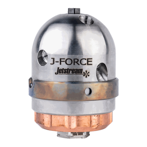
JETStream TUBE SPINNER QSG-123 User manual

TUBE SPINNER™ | NOZZLE OPTIONS
Jetstream of Houston LLP • 5905 Thomas Road Houston, TX 77041
www.waterblast.com • 832-590-1300
TUBE SPINNER™ | NOZZLE FLOW CHART
QSG-123_TubeSpinner_Rev01/22
TUBE SPINNER™
QSG-123
QUICK START GUIDE
ASSEMBLY
PART NO.
CONNECTION TYPE
FEMALE INLET X MALE OUTLET
FLOW
RATE
OUTSIDE DIAMETER LENGTH W/
CAP NOZZLE* SLEEVE
PART NO.
BODY
PART NO.
in mm in mm
52146 1/16" NPT
10.375 9.5 2.72 69 52141 52143
52147 20.375 9.5 2.72 69 52142 52143
51997 1/8" NPT
10.500 12.7 2.66 68 51992 51996
51998 20.500 12.7 2.66 68 51993 51996
52002 1/4" NPT
10.665 16.9 3.14 80 51922 52001
52003 20.665 16.9 3.14 80 51923 52001
52007
3/8" NPT
10.875 22.2 3.30 84 51926 52006
52008 20.875 22.2 3.30 84 51927 52006
64104 30.875 22.2 3.30 84 64088 52006
64105 40.875 22.2 3.30 84 64089 52006
52012
1/2" NPT
11.040 26.4 3.92 100 51941 52011
52013 21.040 26.4 3.92 100 51942 52011
64106 31.040 26.4 3.92 100 64090 52011
64107 41.040 26.4 3.92 100 64091 52011
59900 M7 x 1
10.375 9.5 2.28 58 52141 59906
59901 20.375 9.5 2.28 58 52142 59906
59902 1/8" BSPP
10.500 12.7 2.38 61 51992 59907
59903 20.500 12.7 2.38 61 51993 59907
59904 1/4" BSPP
10.665 16.9 2.68 68 51922 59908
59905 20.665 16.9 2.68 68 51923 59908
ASSEMBLY
PART NO.
CONNECTION TYPE
FEMALE INLET X MALE OUTLET
FLOW
RATE
OUTSIDE DIAMETER LENGTH W/
CAP NOZZLE* SLEEVE
PART NO.
BODY
PART NO.
in mm in mm
64199 1/4" MP LH 10.375 9.5 2.22/2.57 55/65 51956 64193
64200 1/4" MP RH 10.375 9.5 2.22/2.57 55/65 51956 64194
64201 3/8" MP LH 10.500 12.7 2.57/2.99 65/76 51958 64195
64202 3/8" MP RH 10.500 12.7 2.57/2.99 65/76 51958 64196
64203 9/16" MP LH 10.750 19.1 3.55/4.02 90/102 52551 64197
64204 9/16" MP RH 10.750 19.1 3.55/4.02 90/102 52551 64198
64205 9/16" MP LH 20.750 19.1 3.55/4.02 90/102 54256 64197
64206 9/16" MP RH 20.750 19.1 3.55/4.02 90/102 54256 64198
* NPT connection uses FP cap nozzle, M7 connection uses PM cap nozzle, and BSPP connection
uses FB cap nozzle. SOLD SEPARATELY.
* MP connection uses HPFR/HPFL/HPER/HPEL cap nozzle. Lengths are HPFR and HPFL/HPER and
HPEL respectively. SOLD SEPARATELY.
15K PSI
22K PSI
**Flow rates do not include additional flow if a drilled cap nozzle is used.
ASSEMBLY
PART NO.
CONNECTION TYPE
FEMALE INLET X MALE OUTLET
FLOW
RATE
SLEEVE
PART NO.
BODY
PART NO.
OUTSIDE DIAMETER LENGTH W/
CAP NOZZLE FLOW (GPM) AT SPECIFIED PRESSURE (PSI)*
in mm in mm 3,000 4,000 5,000 6,000 7,000 8,000 9,000 10,000 12,500 15,000 17, 5 0 0 20,000
52146 1/16" NPT
152141 52143 0.375 1.9 2.3 2.6 2.9 3.2 3.5 3.7 4.0 4.6 5.1 - -
52147 252142 52143 0.375 3.0 3.5 4.0 4.4 4.8 5.2 5.6 5.9 6.8 7. 5 - -
51997 1/8" NPT
151992 51996 0.500 2.6 3 .1 3.5 3.9 4.3 4.7 5.0 5.4 6.2 7. 0 - -
51998 251993 51996 0.500 5.0 5.9 6.7 7.4 8.0 8.7 9.3 9.9 11.3 12.5 - -
52002 1/4" NPT
151922 52001 0.665 2.4 2.9 3.4 3.8 4.2 4.6 5.0 5.4 6.3 7. 2 - -
52003 251923 52001 0.665 5.2 6.2 7.0 7. 8 8.5 9.2 9.9 10.6 12.1 13.5 - -
52007
3/8" NPT
151926 52006 0.875 3.6 4.3 4.9 5.5 6.1 6.6 7. 2 7.7 9.0 10.1 - -
52008 251927 52006 0.875 7.0 8.2 9.3 10.4 11. 3 12.2 13.1 14.0 15.9 17. 8 - -
64104 364088 52006 0.875 10.0 11.7 13.3 14.7 16.0 1 7. 2 18.4 19.6 22.1 24.6 - -
64105 464089 52006 0.875 13.7 15.9 18.0 19.9 21.5 23.1 24.7 26.2 29.5 32.7 - -
52012
1/2" NPT
151941 52011 1.040 3.0 3.7 4.3 4.9 5.5 6.1 6.6 7.1 8.5 9.7 - -
52013 251942 52011 1.040 6.7 7.9 9.0 10.0 11. 0 12.0 12.9 13.7 15.8 17.8 - -
64106 364090 52011 1.040 10.3 12.2 13.8 15.2 16.7 18 .1 19.3 20.5 23.4 26.1 - -
64107 464091 52011 1.040 14.0 16.4 18.5 20.4 22.2 24.0 25.6 27.1 30.8 34.2 - -
59900 M7 x 1
152141 59906 0.375 1.9 2.3 2.6 2.9 3.2 3.5 3.7 4.0 4.6 5 .1 - -
59901 252142 59906 0.375 3.0 3.5 4.0 4.4 4.8 5.2 5.6 5.9 6.8 7. 5 - -
59902 1/8" BSPP
151992 59907 0.500 2.6 3 .1 3.5 3.9 4.3 4.7 5.0 5.4 6.2 7. 0 - -
59903 251993 59907 0.500 5.0 5.9 6.7 7.4 8.0 8.7 9.3 9.9 11.3 12.5 - -
59904 1/4" BSPP
151922 59908 0.665 2.4 2.9 3.4 3.8 4.2 4.6 5.0 5.4 6.3 7. 2 - -
59905 251923 59908 0.665 5.2 6.2 7.0 7. 8 8.5 9.2 9.9 10.6 12.1 13.5 - -
64199 1/4" MP LH 151956 64193 - - - - - - - 2.3 2.7 3.0 3.4 3.8
64200 1/4" MP RH 151956 64194 - - - - - - - 2.3 2.7 3.0 3.4 3.8
64201 3/8" MP LH 151958 64195 - - - - - - - 3.3 3.9 4.5 5.1 5.7
64202 3/8" MP RH 151958 64196 - - - - - - - 3.3 3.9 4.5 5.1 5.7
64203 9/16" MP LH 152551 64197 - - - - - - - 4.5 5.5 6.4 7.4 8.5
64204 9/16" MP RH 152551 64198 - - - - - - - 4.5 5.5 6.4 7.4 8.5
64205 9/16" MP LH 254256 64197 - - - - - - - 8.8 10.3 11.7 13.1 14.6
64206 9/16" MP RH 254256 64198 - - - - - - - 8.8 10.3 11.7 13 .1 14.6
NOTE: Cap nozzles sold separately

DANGER
!!
THIS PRODUCT CAN BE DANGEROUS IF NOT USED PROPERLY! Always wear
appropriate Personal Protective Equipment (PPE). Detailed PPE information can be found
at: www.fsesgsafety.com and clicking on the JETSTREAM name or by referring to the
yellow JETSTREAM SAFETY WARNING pamphlet (PI-082).
The following Quick-Start Guide is intended to provide the customer with an
expedient reference for Tube Spinner installation and operation. It does not
replace the complete product instructions (PI-123).
This product is sold with the understanding that the purchaser agrees to
thoroughly train all operators and maintenance personnel in the correct and
safe installation, operation, and maintenance of the product and to provide
adequate supervision of personnel at all times. JETSTREAM urges customers to
make complete instructions available to all personnel and ensure they are read
thoroughly before installing, connecting or using the Tube Spinner. Retain these
instructions for future reference. If this product is resold or otherwise conveyed,
the purchaser must pass on these instructions to the new user. If any questions
remain, or to request additional copies, call JETSTREAM at (800) 231-8192 or
(832) 590-1300.
Read the yellow JETSTREAM SAFETY WARNING pamphlet (PI-082) included with
the shipment of the product.
CONNECTING TUBE SPINNER
Prior to the start of any job, make sure only high pressure rated ttings and hoses
are used in the waterblasting system.
Connect the body to the system according the appropriate connection rating
below. DO NOT ASSEMBLE SLEEVE OR FRONT NOZZLE AT THIS STAGE. Once
body is connected, engage the pump and purge the lines for a minute to clear any
possible debris. Disengage pump once lines are purged.
15K PSI RATED TUBE SPINNING NOZZLES
NOTE: When using a thruster, follow the steps below, repeating twice, to
assemble body to thruster then thruster to lance or stinger.
FOR NPT CONNECTIONS:
1. Apply 3-4 wraps of Teon thread sealant tape to the male threads on the
mating lance or stinger.
2. Apply anti-seize compound over the sealant tape for additional protection
against galling in connection threads.
3. Install the nozzle bodies by using appropriate open-end wrench on ats
found on body and tighten 1-2 turns past hand-tight. All NPT pipe connections
should have a minimum thread engagement of (4) threads.
FOR BSPP AND M7 FLAT SEAL CONNECTIONS:
1. BSPP and M7 at seal connections required a copper crush washer between
the male and female connections.
2. Seat copper crush washer in female BSPP or M7 connection on tube spinning
nozzle body.
3. Apply anti-seize compound to male threads of mating lance or stinger.
4. Install the nozzle bodies by using appropriate open-end wrench on ats found
on body and tighten to 20lb-ft.
22K PSI RATED TUBE SPINNING NOZZLES
1. Apply anti-seize compound to the male threads and cone of the mating lance or
stinger.
NOTE: DO NOT use Teon tape on 22K PSI connections.
2. Install the nozzle bodies by using appropriate open-end wrench on ats found on
body and tighten until rmly snug.
NOTE: DO NOT OVERTIGHTEN; damage to coned sealing surface could result.
SLEEVE AND FRONT NOZZLE
Assemble the sleeve and the appropriate front nozzle or cap (See Appendix B of the
Tube Spinner PI (PI-123) for applicable accessories) to the previously connected body.
Assemble front nozzle or cap according to appropriate connection rating below.
15K PSI MODELS
1. Slide sleeve over male end of body.
FOR NPT CONNECTIONS:
2. Apply 3-4 wraps of Teon thread sealant tape to the available male threads found on
the body.
3. Apply anti-seize compound over the sealant tape for additional protection against
galling.
4. Install appropriate FP front nozzle using smooth jaw plier wrench (PN 64119).
5. Tighten 1-2 turns past hand-tight. All NPT pipe connections should have a minimum
thread engagement of (4) threads.
FOR BSPP AND M7 FLAT SEAL CONNECTIONS
6. Seat copper crush washer in female BSPP or M7 connection on appropriate FB or FM
cap nozzle.
7. Apply anti-seize compound to male threads of tube spinning nozzle body.
8. Install the cap nozzle by using appropriate open-end wrench on ats found on cap
nozzle and tighten to 20lb-ft.
22K PSI MODELS
1. Slide sleeve over male end of body.
2. Apply anti-seize compound to the available male threads found on the body.
NOTE: DO NOT use Teon tape on 22K PSI connections.
3. Install appropriate HPFR/HPFL/HPER/HPEL front nozzle by using appropriate open-
end wrench on ats found on cap nozzle and tighten until rmly snug.
NOTE: DO NOT OVERTIGHTEN; damage to coned sealing surface could result.
NOTE: There should be approximately 1/16” to 1/8” clearance between the sleeve and
the front nozzle. With a knife or other sharp object, clear any Teon tape or
exposed compound between the nozzle and sleeve. Conrm sleeve spins freely.
OPERATION
DANGER
!!
Operators and crew need to be clear of spray area as high water pressure is dangerous. The
person controlling the cleaning nozzle must be the operator and must have control of the
pressure. Do not allow a secondary or remote operator have control of pressure. Use only
thoroughly trained operators.
Jetstream of Houston LLP • 5905 Thomas Road Houston, TX 77041 www.waterblast.com • 1-832-590-1300
TUBE SPINNER™ | QUICK START GUIDE QSG-123
WARNING
!!
Remove the nozzle from service if:
a. The body, sleeve, or front nozzle shows signs of cracking or other damage.
b. The wall thickness of these parts is reduced by 25% at any point.
c. The nozzles can no longer hold pressure at water flow rate for which it was sized.
The Tube Spinner can now be used like any standard tube cleaning nozzle.
Periodically inspect the nozzle for damage or excessive wear.
NOTE: For improved reliability and longer life, it is recommended that a lter
of at least 10 microns be used on the water supply inlet. A strainer (100
mesh minimum) must also be used in the water tank (if equipped with
tank).
DANGER
!!
Failure to follow the following instructions will cause unsafe conditions, severe injury can
result.
• DO NOT operate the Tube Spinner above its specied pressure.
• When used on a ex lance and in a tube much larger than the nozzle diameter, the Tube
Spinner must be used with a stinger to prevent the nozzle from “doubling back” for
operator safety.
• Operator must wear ear protection due to the noise generated by the spinning nozzle.
• Never stand in the plane of blasting.
• A Lance Safety Grip is recommended to minimize the risk of a live nozzle exiting the
tube unexpectedly back at the lance operator.
• At high-pressure, the water can be hot. Wear gloves and use precaution to prevent
scalding.
• Place barricades with warning signs or barricade tape around work area. This includes
the waterblast unit and all high-pressure hoses.
• Operator must be outtted with proper safety apparel (refer to yellow JETSTREAM SAFETY
WARNING pamphlet). Body armor is strongly recommended.
!!CAUTION
DO NOT use the Tube Spinner if it has not been cleaned and inspected prior to starting the
working shift.
FOR FURTHER INFORMATION SEE:
https://www.youtube.com/user/JetstreamWaterblast
and the
Jetstream Safety Manual
Other JETStream Tools manuals
