SPX 1507A User manual
© 2004 SPX Corporation
Sheet No.
Issue Date: Rev. G, May 30, 2007
Parts List &
Operating Instructions
for: 1507A
1511A
Form No. 524678
Air-Assist Service Jack
Max. Capacity: 5 and 10 Tons
SPX Corporation
655 Eisenhower Drive
Owatonna, MN 55060-0995 USA
Phone: (507) 455-7000
Tech. Serv.: (800) 533-6127
Fax: (800) 955-8329
Order Entry: (800) 533-6127
Fax: (800) 283-8665
International Sales: (507) 455-7223
Fax: (507) 455-7063
1 of 3
4
23
72
73
5
9
10
16
17
18
19
8
67
11
12
13 14 15 22
21
23
25
20
60
61
62
63
64
74
75
76
77
78
24
1
78
70
72
65
66
67
68
69
71
79
80
81
82
83
84
85
86
87
88
89
90
91
92
93
95
94
79 96
97
98
99
100
101
102
103
104
105
106
107
26
38
39
40
41
42
43
44
45
46
47 48 4950 51
27 28
29
32 33 34 35
31
37 52
53 55
56
57
58
59
54
108
28
30
36
109

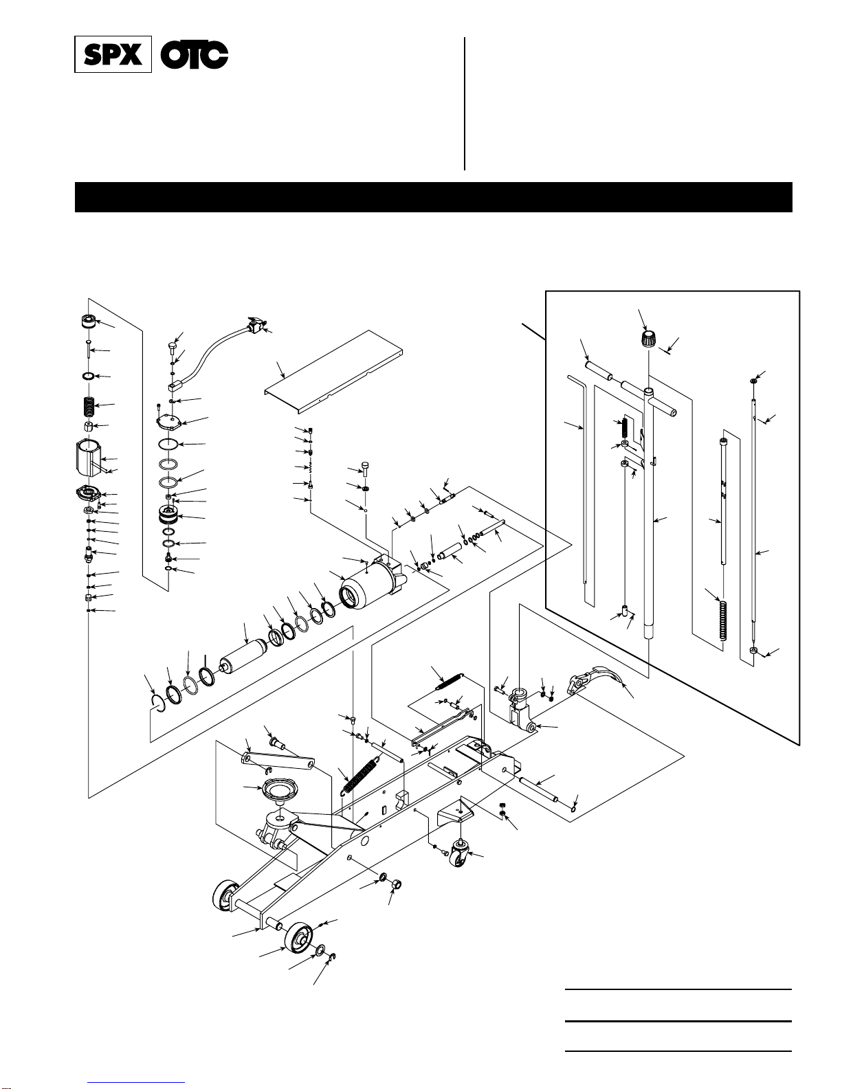
11Frame
22Front Wheel
32Washer
44Snap Ring
53Grease Fitting
62Rod Link
72Bolt
81Saddle
92Lockwasher
10 2 Nut
11 1 Spring
12 4 Bolt
13 1 Bolt
14 4 Snap Ring
15 2 Shaft
16 2 Rear Wheel
17 4 Nut
18 2 Snap Ring
19 1 Shaft
20 1 Washer
21 1 Pin
22 1 Connecting Bar
23 1 Spring
24 2 Snap Ring
25 1 Shaft
26 1 Cover Board
27 1 Snap Ring
28 2 Washer
29 1 O-ring
30 1 Piston Rod
31 1 Piston Ring
32 1 Sealing Washer
33 1 O-ring
34 1 O-ring Retainer
35 1 Snap Ring
36 1 Oil Cylinder Assembly
37 1 Oil Filler Plug
38 1 Steel Ball
39 1 Ball Seat
40 1 Spring
41 1 Screw
42 1 Sealing Washer
43 1 Bolt
44 1 Steel Ball
45 1 Copper Washer
46 1 Bolt
47 1 Steel Ball
48 1 O-ring
49 1 O-ring
50 1 Release Valve Rod
51 1 Pin
52 2 Copper Washer
53 1 Oil Valve Assembly
54 1 Nylon Gasket
55 1 Cylinder Pump
56 2 O-ring
57 2 Washer
58 1 Pin
59 1 Cylinder Pump Plunger
60 1 Handle Socket
61 1 Pedal
62 1 Nut
63 1 Washer
64 1 Bolt
65 1 Handle
66 2 Sleeve
67 1 Knob
68 1 Pin
69 1 Control Rod
70 1 Spring
71 3 Washer
72 3 Screw
73 1 Rod Joint
Parts List & Operating Instructions Form No. 524678, Sheet 1 of 3, Back
Item
No. Qty. Description
74 1 Spring
75 1 Universal Joint Assy.
76 1 Convey Rod
77 1 Washer
78 2 Pin
79 2 Copper Washer
80 1 Oil Valve Assembly
81 1 Nylon Gasket
82 1 Pump Cylinder
83 1 Oil Seal
84 1 Washer
85 1 Copper Washer
86 1 Nut
87 8 Bolt
88 1 Front Cover
89 4 Steel Ball
90 1 Air Pump Housing
91 1 Nut
92 1 Spring
93 1 Washer
94 1 Cylinder Pump Plunger
95 1 Piston Body “A”
96 1 O-ring
97 1 Air Release Rod
98 2 O-ring
99 1 Piston Body “B”
100 3 Bolt
101 1 Air Seal
102 2 O-ring
103 1 O-ring
104 1 Rear Cover
105 1 Snap Ring
106 2 O-ring
107 1 Bolt
108 1 Air Valve
109 1 Handle Assembly
Parts List
Item
No. Qty. Description Item
No. Qty. Description
Shaded areas reflect the latest
revisions made to this form.

© 2004 SPX Corporation
Sheet No.
Issue Date: Rev. G, May 30, 2007
Replacement Kits
Kit numbers followed by an asterisk (j) are used on 1507A units only.
Kit numbers followed by a triangle (
s
) are used on 1511A units only.
Parts List & Operating Instructions Form No. 524678
Item
No. Qty. Description
Air Hose / Air Valve Kit No. 524986
105 1 Snap Ring
106 2 O-ring
107 1 Bolt
108 1 Air Valve
Air Motor Kit No. 531865
79 2 Copper Washer
80 1 Oil Valve Assembly
81 1 Nylon Gasket
82 1 Pump Cylinder
83 1 Oil Seal
84 1 Washer
85 1 Copper Washer
86 1 Nut
87 8 Bolt
88 1 Front Cover
89 4 Steel Ball
90 1 Air Pump Housing
91 1 Nut
92 1 Spring
93 1 Washer
94 1 Cylinder Pump Plunger
95 1 Piston Body “A”
96 1 O-ring
97 1 Air Release Rod
98 2 O-ring
99 1 Piston Body “B”
100 3 Bolt
101 1 Air Seal
102 2 O-ring
103 1 O-ring
104 1 Rear Cover
105 1 Snap Ring
106 2 O-ring
107 1 Bolt
108 1 Air Valve
Caster Kit No. 520775
j
or 520776
s
16 1 Rear Wheel
17 2 Nut
Foot Pedal Kit No. 520791
61 1 Pedal
Grease Fitting Kit No. 520796
51Grease Fitting
Handle Kit No. 524984
109 1 Handle Assembly
Handle Pivot Kit No. 520790
18 2 Snap Ring
19 1 Shaft
60 1 Handle Socket
Handle Retaining Bolt Kit No. 520792
62 1 Nut
63 1 Washer
64 1 Bolt
Item
No. Qty. Description
Handle Return Spring Kit No. 520793
23 1 Spring
Hydraulic and Air Motor Seal Kit
No. 531857
j
or 531858
s
28 2 Washer
29 1 O-ring
32 1 Sealing Washer
33 1 O-ring
34 1 O-ring Retainer
37 1 Oil Filler Plug
42 1 Sealing Washer
45 1 Copper Washer
48 1 O-ring
49 1 O-ring
52 2 Copper Washer
54 1 Nylon Gasket
56 2 O-ring
57 2 Washer
79 2 Copper Washer
80 1 Oil Valve Assembly
81 1 Nylon Gasket
83 1 Oil Seal
84 1 Washer
85 1 Copper Washer
96 1 O-ring
98 2 O-ring
101 1 Air Seal
102 2 O-ring
103 1 O-ring
106 2 O-ring
Hydraulic Unit
No. 531859
j
or 531860
s
13 1 Bolt
27 1 Snap Ring
28 2 Washer
29 1 O-ring
30 1 Piston Rod
31 1 Piston Ring
32 1 Sealing Washer
33 1 O-ring
34 1 O-ring Retainer
35 1 Snap Ring
36 1 Oil Cylinder Assembly
37 1 Oil Filler Plug
38 1 Steel Ball
39 1 Ball Seat
40 1 Spring
41 1 Screw
42 1 Sealing Washer
43 1 Bolt
44 1 Steel Ball
45 1 Copper Washer
46 1 Bolt
47 1 Steel Ball
48 1 O-ring
49 1 O-ring
50 1 Release Valve Rod
51 1 Pin
52 2 Copper Washer
53 1 Oil Valve Assembly
Item
No. Qty. Description
54 1 Nylon Gasket
55 1 Cylinder Pump
56 2 O-ring
57 2 Washer
58 1 Pin
59 1 Cylinder Pump Plunger
79 1 Copper Washer
Inspection Plate Kit
No. 520787
j
or 520788
s
26 1 Cover Board
Leveling Linkage Arm Kit
No. 520785
j
or 520786
s
42Snap Ring
62Rod Link
72Bolt
92Lockwasher
10 2 Nut
Lift Arm Return Spring Kit
No. 520781
j
or 520782
s
11 1 Spring
12 2 Bolt
14 2 Snap Ring
15 1 Shaft
Pump Plunger / Connect Bar Kit
No. 531862
j
or 531863
s
20 1 Washer
21 1 Pin
22 1 Connecting Bar
24 2 Snap Ring
25 1 Shaft
52 2 Copper Washer
53 1 Oil Valve Assembly
54 1 Nylon Gasket
55 1 Cylinder Pump
56 2 O-ring
57 2 Washer
58 1 Pin
59 1 Cylinder Pump Plunger
Release Valve Kit No. 531864
47 1 Steel Ball
48 1 O-ring
49 1 O-ring
50 1 Release Valve Rod
51 1 Pin
Saddle Kit No. 520779
j
or 520780
s
81Saddle
Wheel Kit No. 520777
j
or 520778
s
21Front Wheel
31Washer
41Snap Ring
51Grease Fitting
2 of 3
Parts List & Operating Instructions Form No. 524678, Sheet 2 of 3, Back
Setup
Assemble the Handle
1. Loosen the bolt (Item 64) on the handle socket (60).
NOTE: Item numbers refer to the parts list on page 1.
2. Insert the handle.
3. Tighten the bolt.
WARNING: To prevent personal injury and/or damage to equipment,
•Study,understand,andfollowallinstructionsandsafetyprecautions.Iftheoperatorcannotread
these instructions, the safety precautions and instructions must be read and discussed in the
operator’s native language.
•Beforeusingtheservicejacktoliftavehicle,refertothevehicleservicemanualforrecommended
lifting surfaces on the vehicle chassis.
•Wear eye protection that meets ANSI Z87.1 and OSHA standards.
•Inspectthejack before each use; do not use the jack if it’s damaged, altered, or in poor condition.
•Use the jack for lifting purposes only; use approved safety stands to support the axles before
working on the vehicle.
•Never exceed the rated lifting capacity of the jack.
•Use the jack on a hard, level surface. The jack must be free to roll without any obstructions while
lifting or lowering the vehicle. The wheels of the vehicle must be in the straight-ahead position,
and the hand brake must be released.
•Center the axle on the jack saddle. Off-center loads can damage seals and cause jack failure.
•Lift only dead weight. Do not move the jack while it is supporting a vehicle.
•Stay clear of lifted loads. Use approved safety stands to support the axles before making repairs.
•Do not adjust the safety valve.
•Lower the jack slowly and carefully while watching the position of the jack saddle.
•Use only approved hydraulic fluid (Chevron AW Hydraulic Oil MV or equivalent). The use of alcohol, hydraulic
brake fluid, or transmission oil could damage seals and result in jack failure.
This guide cannot cover every situation, so always do the job with safety first.
Safety Precautions
Air Bleed Instructions
Air can accumulate within a hydraulic system during shipment or after
prolongeduse. Thisentrappedaircausesthejack torespondslowlyortofeel
“spongy.”Toremove the air,followthe instructions forboththe manual pump
and the air pump:
Bleed Air — Manual Pump
1. Open the release valve by turning the release knob counterclockwise.
2. Pump the jack handle six full strokes.
3. Close the release valve by turning the release knob clockwise.
4. If the jack does not immediately respond to pumping the handle, repeat
Steps 1–3.
Bleed Air — Air Pump
1. Place the jack on a level surface.
2. Open the release valve by turning the release knob counterclockwise.
3. Run the air pump for 20 seconds, then close the release valve by turning
the release knob clockwise.
4. Pump the jack pedal until the jack reaches its maximum height.
5. Open the release valve by turning the release knob counterclockwise,
lower the jack to its minimum height.
6. If the jack does not immediately respond to the air pump, repeat steps 1–
5, or follow the priming instructions on the next page.
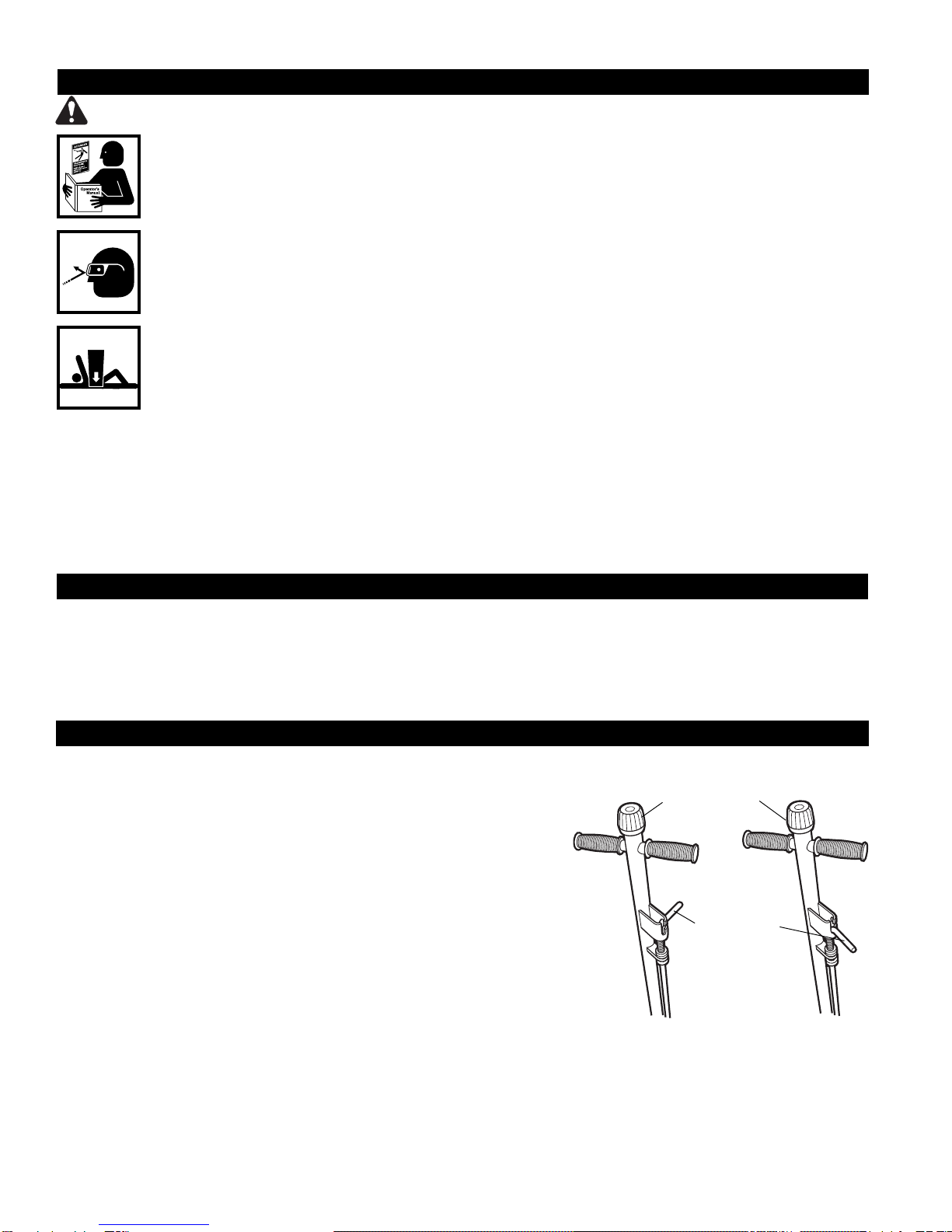
Figure 1
Position A Position B
Release Knob
Control Rod

© 2004 SPX Corporation
Sheet No.
Issue Date: Rev. G, May 30, 2007
Operating Instructions
(Refer to Figure 1)
Control rod in Position A: Allows you to pump the jack using the handle.
Control rod in Position B: Locks the handle in place in three different positions.
1. Connect the shop air supply to the jack. (Shop air should be clean, dry, and regulated at 85–142 psi.)
2. Turn the release knob completely counterclockwise, and place the control rod in Position A.
3. Position the jack under the vehicle using the manufacturer’s recommended lifting points on the chassis. The jack
must be free to roll without any obstructions while lifting or lowering the vehicle. The wheels of the vehicle must be in
the straight-ahead position, with the emergency brake released.
4. Turn the release knob on the jack completely clockwise. Operate the air valve, pump the jack handle, or pump the foot
pedal until the saddle touches the vehicle. Check the placement of the saddle lugs. Finish lifting the vehicle.
5. Place approved safety stands under the vehicle at points that will provide stable support. Before working on the
vehicle, SLOWLY lower the vehicle onto the safety stands by turning the release knob counterclockwise.
Parts List & Operating Instructions Form No. 524678
Priming the Air Pump
If air cannot be bled using the air pump air bleed procedure, the air pump
has lost its prime. To prime the pump:
1. Remove the cover board (Item 26).
2. Loosen the bolt (Item 46; also see Figure 2) one-half turn.
3. Close the release valve by turning the release knob clockwise.
4. Run the air pump while repeatedly tightening and loosening the bolt. (A
small amount of oil may seep from underneath the bolt during this
process).
5. When the piston begins to rise, tighten the bolt.
6. Verify the jack will rise to its full height; add oil to the reservoir if
necessary.
Air Bleed Instructions
continued . . .
Bolt
Figure 2
a. cracked or damaged housing e. malfunctioning swivel heads or adjusting screws
b. excessive wear, bending, or other damage f. loose hardware
c. leaking hydraulic fluid g. modified or altered equipment
d. scored or damaged piston rod
Grease Nipple
IMPORTANT:Dirtisthegreatestsinglecauseoffailureinhydraulic
units. Keep the service jack clean and well lubricated to prevent
foreign matter from entering the system. If the jack has been
exposed to rain, snow, sand, or grit, it must be cleaned before it
is used.
1. Store the jack in a well-protected area where it will not be exposed
to corrosive vapors, abrasive dust, or any other harmful elements.
2. Refer to the illustration, and regularly (at least once per month)
lubricate the moving parts shown.
3. Addgreasetoupperarmgreasenipple(shown)everythreemonths.
4. Ifnecessary,addapprovedanti-wearhydraulicjackoil.IMPORTANT:
Theuseofalcohol,hydraulicbrakefluid,detergentmotoroil,or
transmission oil could damage the seals and result in jack
failure.
5. Inspect the jack before each use. Take corrective action if any of the following problems are found:
Preventive Maintenance
Release
Knob
3 of 3

Troubleshooting Guide
Repair procedures must be performed in a dirt-free environment by qualified personnel who are familiar with this equipment.
Jack does not lift 1. Release valve is open.
1. Close release valve.
2. Low/no oil in reservoir.
2. Fill with oil and bleed system.
3. Air-locked system.
3. Bleed system.
4. Load is above capacity of jack.
4. Use correct equipment.
5. Delivery valve and/or bypass
5. Clean to remove dirt or foreign matter. Replace oil.
valve not working correctly.
6. Packing worn out or defective.
6. Install seal kit.
7. Leak in air line.
7. Locate leak; tighten connections or replace hose.
8. Inadequate air pressure.
8. Set air pressure to 85–142 psi.
Jack lifts only partially 1. Not enough oil.
1. Add oil.
Jack advances slowly 1. Pump not working correctly.
1. Install seal kit, or replace power unit.
2. Leaking seals.
2. Install seal kit.
Jack lifts load, 1. Cylinder packing is leaking.
1. Install seal kit.
but doesn't hold 2. Valve not working correctly (suction,
2. Inspect valves. Clean and repair seat surfaces.
delivery, release, or bypass).
3. Air-locked system.
3. Bleed system.
Jack leaks oil 1. Worn or damaged seals.
1. Install seal kit.
Jack will not retract 1. Release valve is closed.
1. Open or clean release valve.
Jack retracts slowly 1. Cylinder damaged internally.
1. Send jack to OTC authorized service center for repair.
2. Link section is binding.
2. Lubricate link section.
Air motor won’t run 1. Leak in air line.
1. Locate leak, tighten connections, or replace hose.
or runs erratically 2. Inadequate air pressure.
2. Set air pressure to 85–142 psi.
3. Air piston is sticking.
3. Lube air motor by adding a small amount of oil to jack’s
air inlet.
Parts List & Operating Instructions Form No. 524678, Sheet 3 of 3, Back
Trouble Cause Solution
Refer to any operating instructions included with the product for
detailed information about operation, testing, disassembly, reassem-
bly, and preventive maintenance.
Items found in this parts list have been carefully tested and selected
by OTC. Therefore: Use only genuine OTC replacement parts.
Additional questions can be directed to our Technical Service Dept.
This manual suits for next models
1
Table of contents
Other SPX Tools manuals


SPX
SPX Power Team J58T User manual

SPX
SPX 1793 User manual

SPX
SPX HYDRA-GRIP-O-MATIC K82 User manual

SPX
SPX 1505B User manual

SPX
SPX 4302A User manual

SPX
SPX 1727 User manual

SPX
SPX StrutTamer 6070A User manual

SPX
SPX POWER TEAM C12-TON Use and care manual

SPX
SPX Power Team HYDRA-GRIP-O-MATIC PH6 User manual


