Jetter JetViewMobile 104 User manual

User Manual
JVM-104-O08
HMI
60884475_01
We automate your success.

This document has been compiled by Jetter AG with due diligence based on the state of the art as
known to them. Any revisions and technical advancements of our products are not automatically made
available in a revised document. Jetter AG shall not be liable for any errors either in form or content, or
for any missing updates, as well as for any damage or detriment resulting from such failure.
Jetter AG
Graeterstrasse 2
71642 Ludwigsburg
Germany
Phone
Switchboard +49 7141 2550-0
Sales +49 7141 2550-663
Technical hotline +49 7141 2550-444
E-mail
Technical hotline [email protected]
Sales [email protected]
www.jetter.de
Translation of the german original User Manual
Revision 4.12.1
Date of issue 4/3/2023

Jetter AG Table of contents
User Manual – JVM-104-O08 iii
Table of contents
1 Introduction ....................................................................................................................................... 5
1.1 Information on this document .................................................................................................. 5
1.2 Typographical conventions...................................................................................................... 5
2 Safety................................................................................................................................................ 6
2.1 General Information................................................................................................................. 6
2.2 Purpose ................................................................................................................................... 6
2.2.1 Intended use................................................................................................................ 6
2.2.2 Usage other than intended .......................................................................................... 6
2.3 Warnings used in this document.............................................................................................. 7
3 Product description ........................................................................................................................... 8
3.1 Design...................................................................................................................................... 8
3.2 Product features ...................................................................................................................... 8
3.3 Nameplate ............................................................................................................................... 9
3.4 Scope of delivery ..................................................................................................................... 9
4 Technical data................................................................................................................................... 10
4.1 Dimensions .............................................................................................................................. 10
4.2 Mechanical specifications........................................................................................................ 10
4.3 Electrical properties ................................................................................................................. 11
4.3.1 Ports and interfaces..................................................................................................... 11
4.4 Environmental conditions......................................................................................................... 12
4.5 Display ..................................................................................................................................... 12
4.6 Acoustic signal generator ........................................................................................................ 12
4.7 EMI values............................................................................................................................... 13
5 Mechanical installation...................................................................................................................... 14
5.1 Requirements for the installation location................................................................................ 15
5.2 Preparing for installation.......................................................................................................... 16
5.3 Installing the HMI..................................................................................................................... 17
6 Electrical connection ......................................................................................................................... 19
6.1 Pin assignment ........................................................................................................................ 20
6.1.1 M12 male connector – voltage supply, CAN, ignition .................................................. 20

Jetter AG Table of contents
User Manual – JVM-104-O08 iv
7 Identification and Configuration ........................................................................................................ 21
7.1 Operating system..................................................................................................................... 21
7.1.1 Operating system update of the HMI........................................................................... 21
7.2 File system............................................................................................................................... 24
7.2.1 Features ...................................................................................................................... 24
8 Programming .................................................................................................................................... 26
8.1 Abbreviations, module register properties and formats ........................................................... 26
8.2 CANopen STX API .................................................................................................................. 27
8.2.1 STX Functions ............................................................................................................. 27
8.2.2 CANopen object directory............................................................................................ 28
8.3 Storage options - Overview ..................................................................................................... 29
8.3.1 Operating system memory .......................................................................................... 29
8.3.2 File system memory .................................................................................................... 29
8.3.3 Application program memory....................................................................................... 30
8.3.4 Special registers .......................................................................................................... 30
8.3.5 Flag.............................................................................................................................. 30
8.3.6 Storing registers and variables .................................................................................... 31
8.4 Control elements...................................................................................................................... 32
8.4.1 Input keys .................................................................................................................... 32
8.4.2 Digipot ......................................................................................................................... 33
8.5 Ignition and OFF delay ............................................................................................................ 34
8.6 Saving and loading an application program ............................................................................ 36
9 Registers - Overview......................................................................................................................... 37
10 Maintenance ..................................................................................................................................... 45
10.1 Repairs .................................................................................................................................... 45
10.2 Return and disposal................................................................................................................. 45
10.3 Storage and shipment.............................................................................................................. 46
11 Service .............................................................................................................................................. 47
11.1 Customer service..................................................................................................................... 47
12 Spare parts and accessories ............................................................................................................ 48
12.1 Accessories ............................................................................................................................. 48

Jetter AG Introduction | 1
User Manual – JVM-104-O08 5
1 Introduction
1.1 Information on this document
This document forms an integral part of the product and must be read and under-
stood prior to using it. It contains important and safety-related information for the
proper use of the product as intended.
Target groups This document is intended for specialists with appropriate qualifications.
Only competent and trained personnel is allowed to put this device into operation.
During the whole product life cycle, safe handling and operation of the device
must be ensured. In the case of missing or inadequate technical knowledge or
knowledge of this document any liability is excluded.
Availability of
information Make sure this document is kept at the ready in the vicinity of the product
throughout its service life.
For information on new revisions of this document, visit the download area on our
website. This document is not subject to any updating service.
Start | Jetter - We automate your success.
For further information refer to the following information products:
■JetSym software Online Help
Detailed description of software functions with application examples
■Application-oriented manuals
Cross-product documentation
■Version updates
Information about new versions of software products or of the operating sys-
tem of your device
1.2 Typographical conventions
This manual uses different typographical effects to support you in finding and
classifying information. Below, there is an example of a step-by-step instruction:
üThis symbol indicates requirements which have to be met before executing
the following action.
►This sign or a numbering at the beginning of a paragraph marks an action in-
struction that must be executed by the user. Execute the instructions one af-
ter the other.
ðThe target after a list of instructions indicates reactions to, or results of these
actions.
INFO Further information and practical tips
In the info box you will find helpful information and practical
tips about your product.

Jetter AG Safety | 2
User Manual – JVM-104-O08 6
2 Safety
2.1 General Information
When placed on the market, this product corresponds to the current state of sci-
ence and technology.
In addition to the operating instructions, the laws, regulations and guidelines of
the country of operation or the EU apply to the operation of the product. The op-
erator is responsible for compliance with the relevant accident prevention regula-
tions and generally accepted safety rules.
RoHS 2 The device conforms to the EU directive 2011/65/EU (RoHS 2).
2.2 Purpose
2.2.1 Intended use
The JVM-104-O08 is intended for installation in commercial vehicles and self-pro-
pelled machines. It is an HMI with integrated controller for exchange of data with
peripheral devices.
Operate the device only in accordance with the intended conditions of use, and
within the limits set forth in the technical specifications.
Intended use of the product includes its operation in accordance with this man-
ual.
SELV/PELV If this device is not used in a vehicle or mobile machine, a SELV or PELV power
supply unit must be used to supply the device.
2.2.2 Usage other than intended
This device must not be used in technical systems which to a high degree have
to be fail-safe.
Machinery Directive This device is no safety-related part as per Machinery Directive 2006/42/EC, and
must, therefore, not be used for safety-relevant applications. This device is NOT
intended for the purpose of personal safety, and must, therefore, not be used to
protect persons.

Jetter AG Safety | 2
User Manual – JVM-104-O08 7
2.3 Warnings used in this document
DANGER
High risk
Indicates an imminently hazardous situation which, if not
avoided, will result in death or serious injury.
WARNING
Medium risk
Indicates a potentially hazardous situation which, if not
avoided, could result in death or serious injury.
CAUTION
Low risk
Indicates a hazardous situation which, if not avoided, could
result in minor or moderate injury.
NOTICE
Material damage
Indicates a situation which, if not avoided, could result in mal-
functions or material damage.
Jetter AG Product description | 3
User Manual – JVM-104-O08 8
3 Product description
The JVM-104-O08 is a graphical HMI. Thanks to its compact design and in-
tegrated controller, the HMI is versatile and has been specially developed
for harsh applications in commercial vehicles and self-propelled machines.
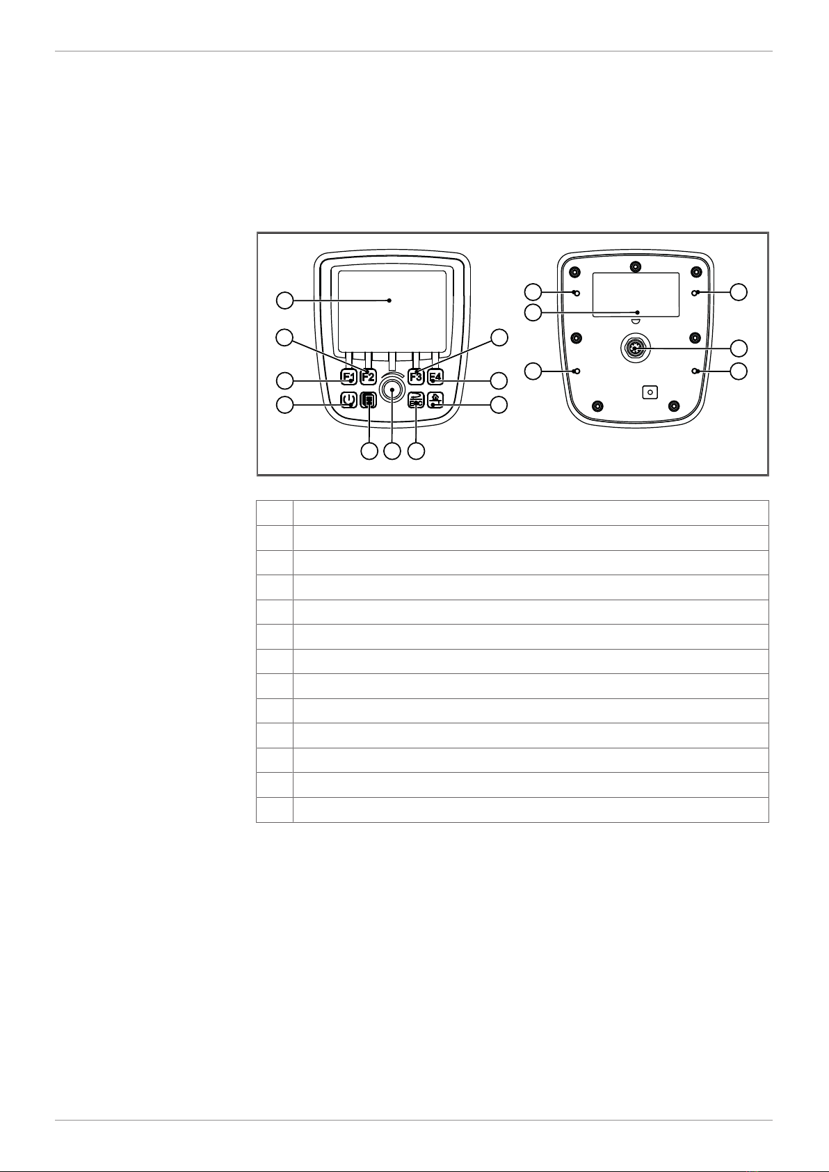
3.1 Design
1
13
12
93
48
10 2
67 5
11
11 11
11
Fig.1: Design
1 TFT display
2 F3 key
3 F4 key
4 Home key
5 ESC key
6 Digipot
7 Scroll key
8 Power key
9 F1 key
10 F2 key
11 Screw hole
12 M12 male connector
13 Nameplate
3.2 Product features
■Display: 3.5” TFT, 320x240px
■CPU: ARM11, 500MHz, 128MB RAM, 512MB Flash
■Surface mount model with connector M12x1
■Input: 8 keys, 1 DigiPot
■Ports and interfaces: 1x CAN
■Front/rear degree of protection: IP65/IP65
Jetter AG Product description | 3
User Manual – JVM-104-O08 9
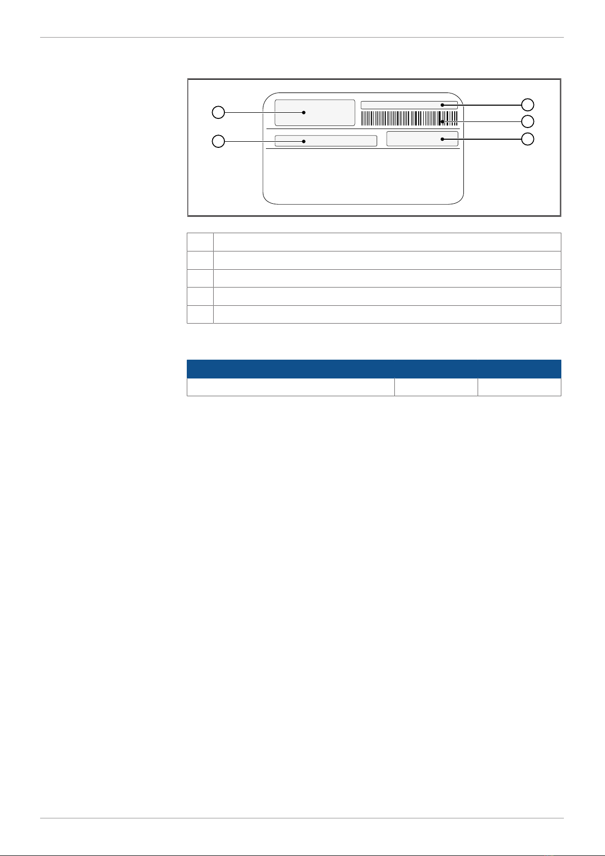
3.3 Nameplate
2
3
4
1
5
Fig.2: Nameplate
1 Logo
2 Serial number
3 Barcode
4 Article number and hardware revision
5 Model code number
3.4 Scope of delivery
Scope of delivery Item number Quantity
JVM-104-O08 10001558 1

Jetter AG Technical data | 4
User Manual – JVM-104-O08 10
4 Technical data
This chapter contains electrical, mechanical data and operating data of the
JVM-104-O08.
4.1 Dimensions
119.8
27.955
83
O3.1
4 x
55.3
5.6 28.4
66.5
104.9
Fig.3: Dimensions in mm
4.2 Mechanical specifications
Parameter Description Standards
Weight 350g
Vibration
Broadband noise 10Hz / 0.005(m/s2)2/Hz DINEN60068-2-64
200Hz / 0.02(m/s2)2/Hz
300Hz / 0.01(m/s2)2/Hz
350Hz / 0.002(m/s2)2/
Hz
Duration 3x 24h
Shock resistance
Type of shock Half-sine wave DINEN60068-2-27
Intensity and duration 30g (300m/s2) for
18ms
Number and direction 18shocks in all 6direc-
tions
Degree of protection
Front panel IP65 DINEN60529
Rear panel IP65
Tab.1: Mechanical specifications

Jetter AG Technical data | 4
User Manual – JVM-104-O08 11
4.3 Electrical properties
Power supply
VBAT_ECU Parameter Description
Nominal voltage DC12V or 24V
Maximum current 2A
Typical logic current con-
sumption (VBAT_ECU)
170mA at DC12V
90mA at DC24V
Power consumption Approx 2W
Integrated protective
functions
Reverse polarity protection, overvoltage, short volt-
age pulses
Permissible voltage
range VBAT_ECU
DC8V...32V
Permissible voltage
range at terminal 31 (ig-
nition)
DC8V...32V
Tab.2: Power supply VBAT_ECU
4.3.1 Ports and interfaces
CAN interface Parameter Description
Baud rate 125kBaud, 250kBaud, 500kBaud
Protocol CANopen
Default node ID on the
CANopen bus
127(0x7F)
Terminating resistance Does not exist.
Must be connected externally.
Cable specification Twisted pair conductors, unshielded
Tab.3: CAN interface specification
CAN bus cable Parameter Description
Wire cross-section 500kBaud: 0.34mm²…0.50mm2
250kBaud: 0.34mm²…0.60mm2
Cable capacitance 60pF/m max.
Resistivity 500kBaud: Max. 60Ω/km
250kBaud: Max. 60Ω/km
Number of cores 2
Twisting CAN_L and CAN_H cables are twisted pairwise
Tab.4: Specification - CAN bus cable
Jetter AG Technical data | 4
User Manual – JVM-104-O08 12
The maximum permitted cable length depends on the baud rate being used and
the number of CANopen devices being connected.
Baud rate Max. cable length Max. stub length Total cable length
500kBaud 100m 5m 30m
250kBaud 250m 10m 60m
Tab.5: Cable lengths
4.4 Environmental conditions
Parameter Description Standards
Operating temperature -20°C...+65°C ISO16750-4
Climatic conditions Humid heat
Storage temperature -20°C...+70°C ISO16750-4
DINEN60068-2-1
DINEN60068-2-2
Relative humidity 10% … 95% DINEN61131-2
Pollution degree 2 DINEN61131-2
Tab.6: Environmental conditions
4.5 Display
Parameter Description
Type TFT LCD flat screen monitor
Resolution 320 x 240Pixel
Size 3.5"
Backlighting LED, typ. 350cd/m2 , dimmable
Horizontal viewing angle 70° to each side
Vertical viewing angle 50° from above, 70° from below
Tab.7: Technical data – display
4.6 Acoustic signal generator
Parameter Description
Type Loudspeaker Adjustable frequency
and volume.
Volume 83dB 10cm distance and res-
onance frequency
2,670Hz
Tab.8: Acoustic signal generator

Jetter AG Technical data | 4
User Manual – JVM-104-O08 13
4.7 EMI values
The JVM-104-O08 has E1 approval according to ECE R10 Rev. 5 and CE con-
formity according to ISO 14982.
Pulses ISO7637-2 Test pulse Values Function class
1 -450V C
2a +37V A
2b +20V C
3a -150V A
3b +150V A
4 Ua1: -12V / 50ms
Ua2: -5V / 500ms
A (24V systems)
Ua1: -6V / 15ms
Ua2: -2.5V / 1,000ms
C (12V systems)
5b Load dump, capped
70V / 2Ω
A
Tab.9: Pulses ISO7637-2
Irradiation ISO11452 Parameter Values Function class
Irradiation 20MHz ... 2GHz 30V/m A
Tab.10: Irradiation ISO11452
ESDEN61000-4-2 Parameter Values Function class
Contact discharge ±4 kV (to conductive
surfaces)
A
Discharge through air ±8 kV (to insulating
surfaces)
A
Tab.11: ESDEN61000-4-2

Jetter AG Mechanical installation | 5
User Manual – JVM-104-O08 14
5 Mechanical installation
NOTICE
Damages to material or functional impairment due to
welding
Welding on the chassis may damage the device material, or
impair device functions.
►Before you start welding, disconnect all connections be-
tween the device and the electric system of the vehicle.
►Protect the device from flying sparks and welding beads
(splatter).
►Do not touch the device with the welding electrode or
earth clamp.
NOTICE
Dirt and moisture can affect the electrical connections
►Protect unused pins using blanking plugs.
►Protect all electrical connections with appropriate single
wire seals.
►Clean the area around a connector prior to removing the
mating connector.

Jetter AG Mechanical installation | 5
User Manual – JVM-104-O08 15
5.1 Requirements for the installation location
The installation location must meet the following requirements:
■The installation location must allow air to circulate.
■The installation location must be of sufficient size.
■The device must be easily accessible to allow for service work.
Space required for
installation and
service
It should be possible to disconnect the connectors at any time.
70
Fig.4: Space requirements for installation work (in mm)
Avoiding unsuitable
installation locations The following installation locations are unsuitable for mounting the device:
Unsuitable installation location Reason
Outdoor installation The device must not be exposed to
rain or a jet of water. Do not use a
steam jet or other such devices to
clean the device.
Installation location close to heat-sen-
sitive materials
The materials could become warped
or misshapen as a result of heat pro-
duced by the device.
Tab.12: Unsuitable installation locations
Jetter AG Mechanical installation | 5
User Manual – JVM-104-O08 16
5.2 Preparing for installation
Mounting
accessories Use the following accessories for installation:
Accessories Item number
Mounting plate for RAM Mount ball
consisting of mounting plate and screws for housing with
Deutsch or M12 connector, without RAM Mount attach-
ments
10001621
OR
Mounting plate for RAM mount arm with suction cup
consisting of mounting plate and screws for housings with
Deutsch/M12 connector including RAM Mount arm with
suction cup
10001551
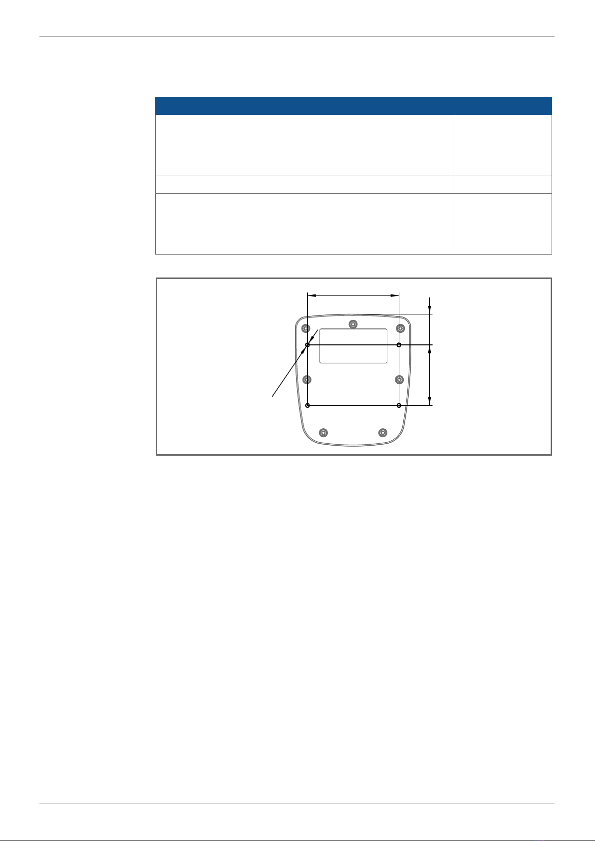
Screw holes
27.955
83
O3.1
4 x
Fig.5: Screw holes, dimensions in mm

Jetter AG Mechanical installation | 5
User Manual – JVM-104-O08 17
5.3 Installing the HMI
The illustration below shows how to install the device:
234
5
1
6
Fig.6: Installation drawing
1 2 x self-locking nuts
2 4 x screw for fixing to the JVM-104-O08
3 RAM Mount ball
4 Mounting plate with opening for connector
5 2 x countersunk screws for mounting a RAM Mount ball
6 Alternate position of the RAM Mount ball
1. Screw the desired RAM Mount attachments onto the mounting plate.
2. Hold the JVM-104-O08 against the mounting plate from behind. The connec-
tors must be accessible through the openings in the mounting plate.
3. Screw the mounting plate onto the JVM-104-O08.
Jetter AG Mechanical installation | 5
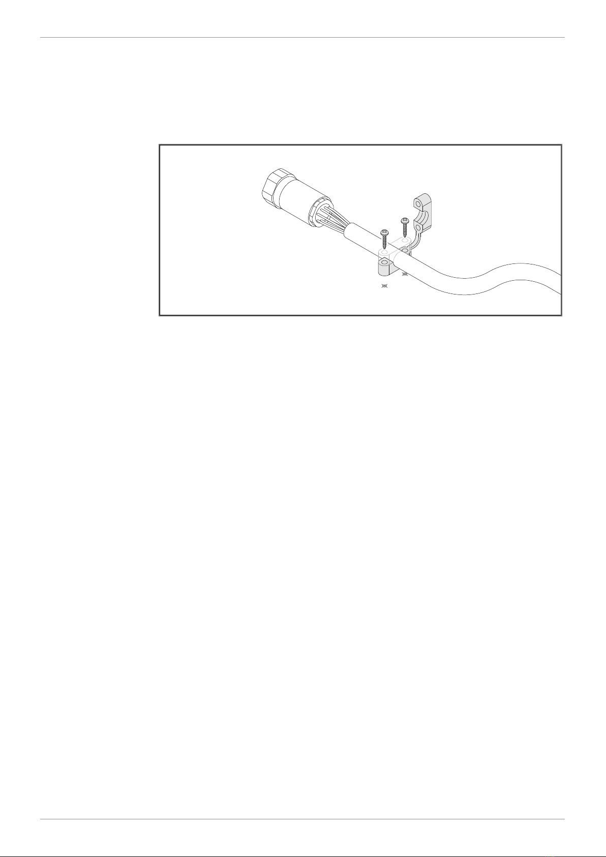
User Manual – JVM-104-O08 18
Installing the strain
relief Install strain reliefs for the connecting cables.
■Ensure that there is sufficient clearance between the strain reliefs and the
connectors.
■Connectors must not be obstructed, so that they can be removed in the
event of service.
Fig.7: Installing the strain relief

Jetter AG Electrical connection | 6
User Manual – JVM-104-O08 19
6 Electrical connection
NOTICE
Damages to material or functional impairment
Improper implementation of the wiring harness may cause
mechanical stress.
►Protect the cables from bending, twisting or chafing.
►Install strain reliefs for the connecting cables.
NOTICE
Surges resulting from missing protection or fusing
Surges may cause malfunctions or damage to the product.
►Protect the voltage inputs from surges according to the
requirements.
►Ensure that the device is handled in accordance with
ESD regulations.

Jetter AG Electrical connection | 6
User Manual – JVM-104-O08 20
6.1 Pin assignment
6.1.1 M12 male connector – voltage supply, CAN, ignition
Function The M12 connector has the following function:
■Power supply to the JVM-104-O08
■CANopen bus interface: CAN 1
■Recognition of the ignition signal
INFO Ignition
To launch the JVM-104-O08, pin 3 (Ignition+) must be con-
nected with pin 1. The ignition control signal (Ignition+) is is-
sued when the key is in position
Ignition ON
.
INFO Current consumption
When the device is energized, the current consumption is
temporarily higher. To ensure a reliable start-up of the device,
provide at least 3 times the typical current required.
1
2
3
5
4
6
7
8
Fig.8: 8-pin M12 male
connector
Pin Signal
1VBAT_ECU
2n. c.
3IGN (ignition)
4n. c.
5CAN_L
6GND
7CAN_H
8SHLD
Mating part The following jack is a mating part to the 8-pin M12 connector:
Parameter Description
Manufacturer e.g. BELDEN Lumberg automation
Manufacturer's item no. RKCN 8/9
Wire size range 0.5mm2 (AWG 20)
Tab.13: Compatible M12 connector (female)
Other manuals for JetViewMobile 104
2
This manual suits for next models
1
Table of contents
Other Jetter Recording Equipment manuals


