ETC Unison AV/Serial Interface v1.1.0 User manual

ETC®Quick Guide
Unison®AV/Serial Interface v1.1.0 (LM v1.9.1)
Unison AV/Serial Interface v1.1.0 Quick Guide Page 1 of 10 Electronic Theatre Controls, Inc.
Americas
3031 Pleasant View Road, P.O. Box 620979, Middleton, Wisconsin 53562-0979 USA
Tel: +608 831 4116
800 688 4116
Fax: +608 836 1736
800 555 8912
Europe
Unit 5, Victoria Industrial Estate, Victoria Road, London W3 6UU, UK
Tel: +44 (0)20 8896 1000
Fax: +44 (0)20 8896 2000
Asia
Room 605-606, Tower III Enterprise Square, 9 Sheung Yuet Road, Kowloon Bay, Kowloon, Hong Kong
Tel: +852 2799 1220
Fax: +852 2799 9325
Web:
www.etcconnect.com
Email:
(US) mail@etcconnect.com
(UK) mail@etceurope.com
Service:
(US) service@etcconnect.com
(UK) service@etceurope.com
(Asia) [email protected]
Comments about this document: techcomm@etcconnect.com
7081M1301-1.1.0
Rev A
Released 11/2004
Copyright © 2004 ETC. All Rights Reserved.
Product information and specifications subject to change.
Overview
This quick guide is intended for use by ETC trained technicians and technicians
programming devices that will communicate with Unison via a serial interface. It assumes
an intermediate level of familiarity and experience with the equipment involved.
With Unison
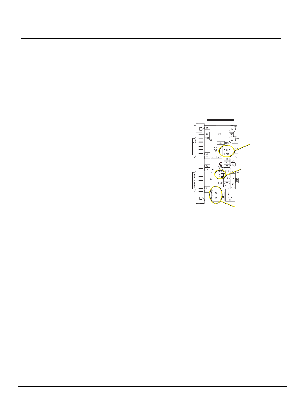
The Unison AV/Serial Interface station provides a method for
PCs or any other type of device capable of RS232 serial
communication to control and interact with a Unison control
system. The AV/Serial Interface acts as virtual station with
similar functionality to existing station types except you
manipulate the virtual buttons, faders and rates with serial
commands. Presets, macros or other Unison station events
may be activated or deactivated using this station. Feedback
information is passed back in the form of responses and by
polling the status of the virtual buttons and faders (similar to
the visual feedback LEDs on a standard wall station).
This station, with neuron code v1.1.0 and later, also features
a short configuration independent communications protocol
for ease of implementation. Due to the simplicity of the
station, more than one station may be used in a system.
Contact ETC Project Management for assistance.
Light Manager™ Software
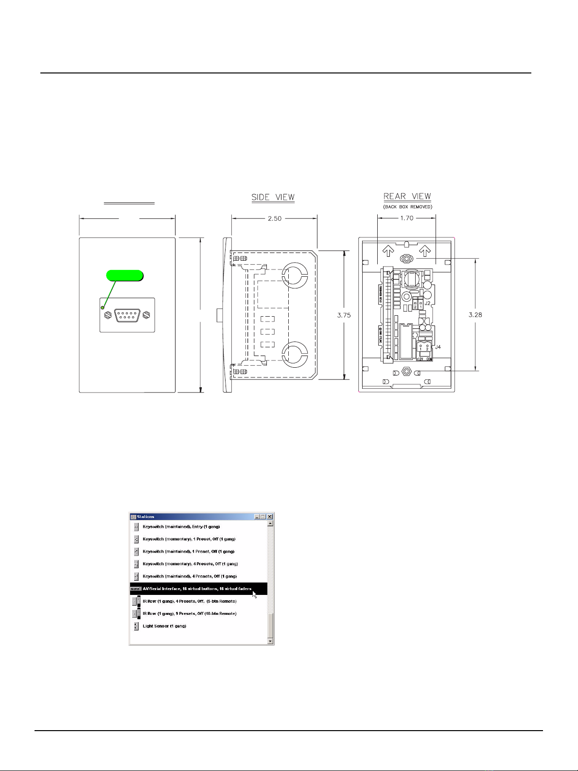
The functionality of the AV/Serial Interface station, in a Unison system is easily configured
by adding the new AV/Serial Interface station into an existing Light Manager configuration.
The default station type is a 16 button, 16 fader, and 16 zone levels (ST3300). By default,
the station has no assignments.
The Unison AV/Serial Interface station protocol (the serial communication as defined in
this document) defines the serial interaction with the station itself. It supports manipulation
of four virtual objects to control the functions configured in Light Manager:
• Buttons: These represent the station's virtual buttons. A button's state can be maintained on
as though someone were holding it down, or simply be off. There is also a command to
execute a “press”, which simulates a press and release of a button (the most common
use). Each virtual button on the station has a corresponding virtual LED to indicate
function state. These LEDs are controlled by the Unison processor and are read only.
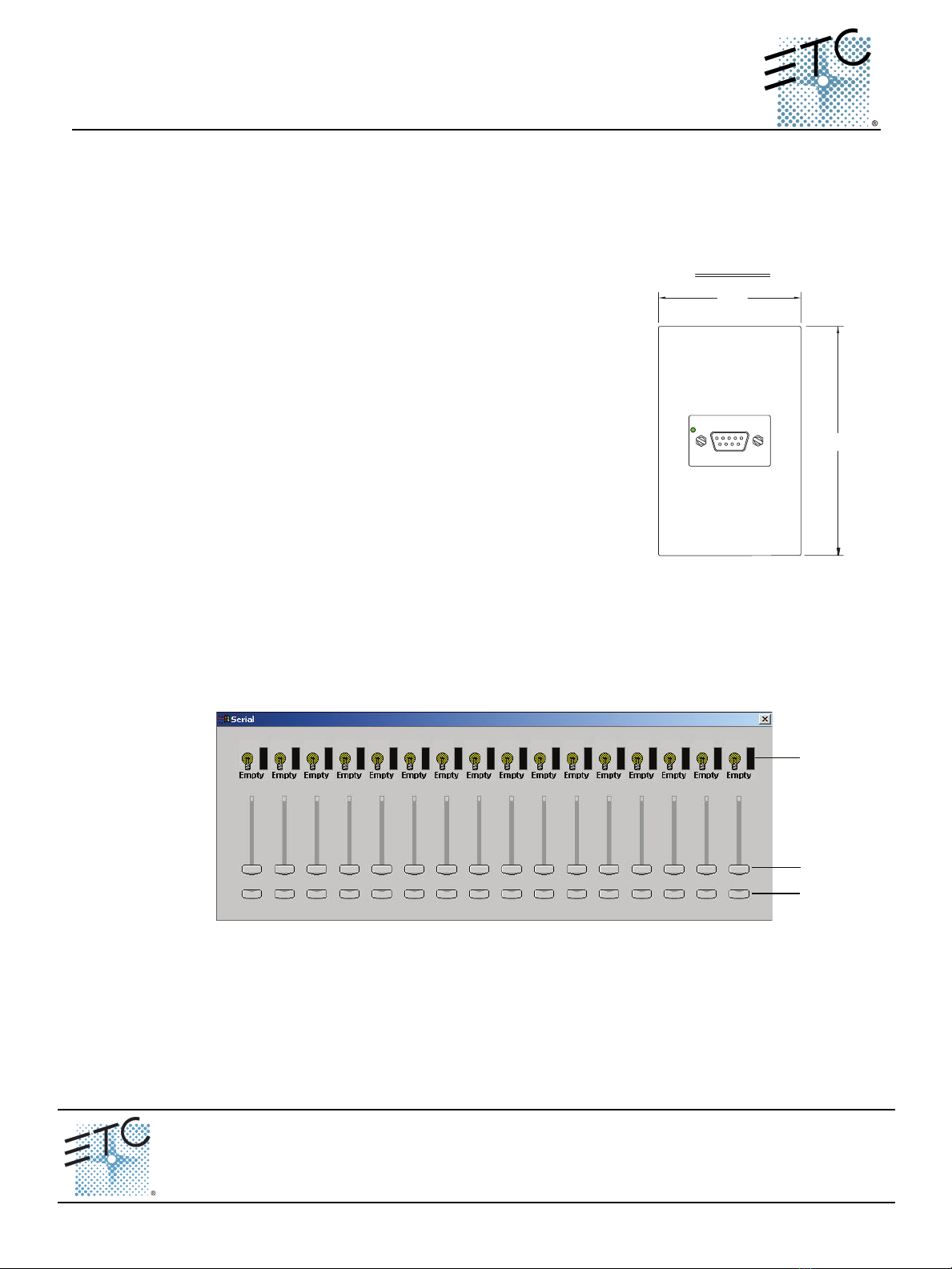
2.80"
4.50
"
FRONT VIEW
AV/Serial Interface
Computer
Level
Fader
Button

Quick Guide:
Unison AV/Serial Interface v1.1.0 Quick Guide
Unison AV/Serial Interface v1.1.0 Quick Guide Page 2 of 10 Electronic Theatre Controls, Inc.
• Faders: These represent the station's virtual faders. Faders can be set to any level from zero
to full on (100%). Each virtual fader also has a virtual LED, which is also a read-only
property.
• Rates: The station also utilizes fade rates to facilitate smooth and level transitions given the
limited bandwidth of RS232. There is a configurable rate that corresponds with each fader
of the station. When a new fader level is given, the fader is moved at the set rate to the
new level. Rate is set in a unit of seconds.
• Levels: A Level is a configurable feedback mechanism for up to 16 zones that report the
actual level of the configured zone to the serially connected device.
With Emphasis [Serial Button Protocol]
The Unison AV/Serial Interface has a second mode of
operation that interfaces with an Emphasis
Facepanel or ECS LPC via RS232 and Serial Button
Protocol. This mode of operation is set either by
installing the jumper on J2 to the “B” side (the
preferred method), or by sending a specified serial
command to the device. In this mode, commands that
set the LED state for buttons 1 thru 16 result in
activation of macros 101 thru 116 on the serially
connected Emphasis. Please see the Emphasis User
Manual (v1.4.0 or later) for more details about the
Emphasis Serial Button Protocol.
The Unison AV/Serial Interface station protocol as
defined in this document is still accepted from host to
station to allow any reconfiguration of the station. The
Unison Light Manager configuration must be
configured with the default AV/Serial Interface station
type (ST3300). Enabling Emphasis mode forces the
station to be the default type if it was previously changed; alternate station types are not
allowed. If the Unison configuration uses any other station, the physical station will not
bind/connect to the system.
Emphasis mode Light Manager configuration example:
The 16 buttons of the AV/Serial Interface station are configured as zone bump toggle for
zones 1 - 16. When zone one’s level changes from 0% to 100%, the AV/Serial Interface
station sends a command to execute macro number 101 of the serially connected
Emphasis system. Nothing is sent when zone one is returned to 0%.
PCB Top Side
Unison Link
Power (ULP)
J2 jumper for
Emphasis Serial
Button Protocol mode
Unison Aux
Power (+24Vdc)

Quick Guide:
Unison AV/Serial Interface v1.1.0 Quick Guide
Unison AV/Serial Interface v1.1.0 Quick Guide Page 3 of 10 Electronic Theatre Controls, Inc.
Set Up
Station Installation
• The AV/Serial Interface station fits in a standard single-gang back box.
• It requires 24vdc Aux power (J3) and ULP (J1) and an ESD ground wire.
• There is a green LED on the front of the station next to the RS-232 connector (shown below)
that will remain on until the station is bound at the Unison processor. After the station is
bound, it will briefly flash on as it receives information (including individual keystrokes
while using a terminal emulator).
• The AV/Serial Interface station is similar in appearance to Unison PC Interface station. It is
important to note that the AV/Serial Interface and the PC Interface station have different
electronics and are not interchangeable. In addition, the AV/Serial interface station must
include neuron code v1.4 or later to function properly with Light Manager v1.9.1.
Light Manager Configuration
Reference the Unison®Light Manager™ Software Quick Guide version 1.9.1 for detailed
instructions on adding the AV/Serial Interface station to your configuration.
• Add an AV/Serial Interface to the Unison configuration.
• The default station type is 16 virtual buttons, 16 virtual faders and 16 levels (ST3300).
• You should specify the neuron ID in the station's properties just like any other station. (This
is the preferred method of binding stations as it simplifies the process of connecting a
station.)
• Configure the buttons, faders and level assignments in Light Manager as desired to be used
as inputs (causing events in Unison), or as monitors (watching an LED state to see status
2.80"
4.50"
FRONT VIEW
AV/Serial Interface
Computer
Green LED

Quick Guide:
Unison AV/Serial Interface v1.1.0 Quick Guide
Unison AV/Serial Interface v1.1.0 Quick Guide Page 4 of 10 Electronic Theatre Controls, Inc.
of some other event in Unison, or monitoring a zones level).
Communication between the station and the serial host
• Use a standard RS232 straight-through cable.
• Station 9 pin “D style” connector pinout: pin 2 - transmit data (TX), pin 3 - receive data (RX),
pin 5 - Common
• Com port settings are 9600 baud, 8 bits, no parity 1 stop bit, and Xon/Xoff flow control.
Station Configuration with a Computer Example
• Connect your computer to the station with a standard RS232 straight-through cable.
• Station 9-pin “D” style connector pinout: pin 2 - Transmit data (TX), pin 3- Receive data
(RX), pin 5 - Common.
• Use a communications terminal application, such as Hyper Terminal, to interface with the
station.
• Com port settings are 9600 baud, 8 bits, no parity, 1 stop bit, and Xon/Xoff flow control.
Sample commands:
Commands are terminated with carriage return:
• SC 1.1 (Turn on echo mode)
• You won't see anything when you type until echo mode is
turned on. Default is off - see Configuration Settings (nn.cf)
on page 7)
• GV (Get version number)
•SeeProtocol Version (pv) on page 6)
• GS2 (Get neuron ID)
•SeeStation Status (ss) on page 6)
• SC3.1 (Set level and fader scale to 0-100, or percentages)
• GC3 (Get configuration index 3's value)
• GC (Get all of the configuration values)
•SeeConfiguration Settings (nn.cf) on page 7)
• GT (Get the station type)
•SeeStation Type (st) on page 8)
• SB1.2 (Set button 1 - execute a toggle)
•SeeButton States (bs) on page 5)
• SF1.50 (Set fader 1 to a level of 50)
•SeeLevel (ll) on page 6 and Fade Rate (rr.dd) on page 6)

Quick Guide:
Unison AV/Serial Interface v1.1.0 Quick Guide
Unison AV/Serial Interface v1.1.0 Quick Guide Page 5 of 10 Electronic Theatre Controls, Inc.
Unison AV/Serial Interface Station Protocol Command Structure
Multi-byte Commands
Multi-byte commands use the following format where [bracketed] parameters including a
separating delimiter are optional as necessary: <verb><noun>[<index>][.<value>]
All multi-byte commands are terminated by a carriage return: ^M (0x0D)
Index and Value Details
Default values and settings are in bold.
Index (nn)
Button States (bs)
Verbs Verb Definition Nouns
S = Set “Do this” B = Button
G = Get “Tell me about...” C = Configuration
R = Reply A response to a Get command F = Fader
U = Update An automatic system response
initiated by a status change of an
item on the station (such as a
button’s LED turning on)
L = Level
M = Memory
R = Rate
S = Status
T = Type
V = Version
Object Get Command Get Reply Set Command Update Reply
Button GB nn RB nn.bs.ld SB nn.bs UB nn.bs.ld
Fader GF nn RF nn.ll.ld SF nn.ll UF nn.ll.ld
Rate GR nn RR nn.fr SR nn.rr.dd
Level GL nn RL nn.ll UL nn.ll
Configuration GC nn RC nn.cf SC nn.cf
Station Type GT RT st ST st
Protocol Version GV RV pv
Station Status GS nn RS nn.ss
Memory GM nn RM nn.mm SM nn.mm
Help ? <text>
Notes:
• Reply messages are read only status messages that are sent from the Unison processor and output by the
station. They cannot be issued by the serial host.
0=All
nn = Index of the Object
0 = Off (Maintained)
1 = On (Maintained)
2 = Executes a button press
Notes:
• At reset, button states are set to 0 unless saved to memory.

Quick Guide:
Unison AV/Serial Interface v1.1.0 Quick Guide
Unison AV/Serial Interface v1.1.0 Quick Guide Page 6 of 10 Electronic Theatre Controls, Inc.
LED States (ld) [Read Only]
Level (ll)
Fade Rate (rr.dd)
Protocol Version (pv)
Station Status (ss)
0=Off
1=On
2=Ondim
3=Blinkslow
4=Blinkfast
ll = 0-255 (default) [or 0-100]
Notes:
• At reset, fader levels are set to 0 unless saved to memory.
• The level scale (0-255 or 0-100) is set in Configuration Settings, index 3.
• Level defaults to a scale of 0-255
rr = 0-300 seconds [0 or 0.0 = disable rate (default)]
dd = 0-9 tenths of a second
Notes:
• Defaults to disable rate (0)
pv = Software version of the Serial Button Protocol
Notes:
• The version is Hex encoded where the high byte is the major release and
the low byte is the minor release.
nn - index
1 Hex encoded value, 4 characters (i.e. 0x0010 = installed but unbound / 0x0020 = installed & bound)
Bit Description
0 Station reset occurred
1 Station wink occurred
2 A command error occurred
3 UART error occurred
4,5 Unison install status (00 = unistalled, 01 = installed, 10 = bound)
6-15 Unused
2 Neuron ID string
3 Button binding
4 Button LED binding
5 Fader LED binding
6 Fader binding (Hex encoded bit pattern)
7 Level binding (Hex encoded bit pattern)
8 Node number
Notes:
• If the “echo” configuration flag is set, the update reply is suppressed and a question mark (?)
followed by the bad command is sent.
• If the “no update” configuration flag is set, bits 0 thru 3 will be clear bits when status is read.
Otherwise, these will always be read as 0.
• Indexes 3 thru 7 indicate the state of virtual object bindings to the Unison Control Module.
Non-zero bindings (for a type that does not support an object) may indicate a mismatch in
binding/connection of the station. Rebinding via service pin and reconnecting at the Control
Module face panel may be necessary (i.e. if type is 100 and fader LED binding equals 1,
there is a binding/connection mismatch).

Quick Guide:
Unison AV/Serial Interface v1.1.0 Quick Guide
Unison AV/Serial Interface v1.1.0 Quick Guide Page 7 of 10 Electronic Theatre Controls, Inc.
Configuration Settings (nn.cf)
Memory
(nn) Index Settings (cf)
1Echo 0 = off, 1 = on
2 No update 0 = off, 1 = station will be polled by the computer
3 Level & fader scale 0 = 0-255, 1 = 0-100
4 Reply terminator 0 = CRLF, 1 = CR (LF is always ignored on
receiving)
5 Packet mode 0 = disabled, 1 = enabled
6 Emphasis mode 0 = disabled, 1 = enabled
7 Configuration jumpers Values of 4 configuration bits. Only bit 0 has
jumper pins on the PCB.
99 Reset station
1 = set configuration to defaults, clear memories,
set fade rates to 0, set key and fader LEDs to off,
set levels to 0, and clear bindings.
Notes:
• Configuration switches are stored in EEROM and are retained during a
power loss.
• When packet mode is enabled, commands are prefixed with a one-byte
preamble. The eighth bit (MSB) is always a logical one and the lower
7 bits should contain the number of bytes in the command. The length
should only be calculated for the command and does not include the
preamble or the terminator. Valid commands are replied with an ACK
command. Invalid commands are replied with a NAK command.
Packet mode cannot be enabled until Echo is turned off.
• Configuration jumper settings: J2-B enables Emphasis mode.
• Emphasis mode only affects outgoing messages (station to host).
nn Index Settings
1 Fader levels 0 = clear, 1 = save
2 Fader rates 0 = clear, 1 = save
3 Button states 0 = clear, 1 = save
Notes:
• Get Memory returns 1 if any item saved is in a non-default state.

Quick Guide:
Unison AV/Serial Interface v1.1.0 Quick Guide
Unison AV/Serial Interface v1.1.0 Quick Guide Page 8 of 10 Electronic Theatre Controls, Inc.
Station Type (st)
The station's software is capable of mimicking several ETC standard button and fader
station types. However, changing the type from its default 16 buttons, 16 faders, and 16
levels (ST3300) has its disadvantages, most notable of them are a reduced number of
buttons and faders, a total loss of the support for Level feedback, and loss of support for
Emphasis Serial Button Protocol.
Most users will make the best use of the station as its default type and will not need to
make use of this feature. The default station type yields the highest quantity of controllable
items even if they are left unused, and will not preclude use of Levels. The default
AV/Serial Interface station type (ST3300) is also the only type allowed when Emphasis
mode is enabled (see below).
The (st) property sets the type of station that the AV/Serial Interface station will emulate.
Although there is nothing preventing you from setting this property to any value, only the
ones listed below will be recognizable by a Unison processor.
When comparing the button and fader mapping to a physical station, faders are numbered
right to left and buttons 1-10 are on the right side of the faders and 11, 12 are on the left.
The AV/Serial Interface station's buttons, faders, and levels are each numbered right to
left as 1-16 respectively
Binding/Connecting Stations
The AV/Serial Interface and the Unison processor maintain their binding status separately.
(It’s possible to have one bound and the other unbound.) For this guide, “Connect” and
Station ID Station Description
100 5 buttons
200 10 buttons
800 12 buttons, 4 faders
900 12 buttons, 7 faders
1000 12 buttons, 10 faders
1200 12 buttons, 13 faders
1300 12 buttons, 16 faders
1600 8 switch satellite board
1800 5 buttons,
1900 1 key switch, 5 buttons
3300 16 buttons, 16 faders (AV/Serial Interface type) (Default)
Notes:
• Changing the station type also processes an Escape command which clears bindings and
takes the station to an uninstalled state (it may subsequently rebind erroneously with the
Unison Control Module). This does NOT however disconnect the station from the Unison
Control Module if the station was currently connected (bound at the processor). Proper
operation will only be restored if the station is disconnected and reconnected as the new
station via the Setup Menu of the Unison Control Module face panel LCD, and then finally
reissuing the station service pin (see Single-byte commands).

Quick Guide:
Unison AV/Serial Interface v1.1.0 Quick Guide
Unison AV/Serial Interface v1.1.0 Quick Guide Page 9 of 10 Electronic Theatre Controls, Inc.
“Disconnect” refers to the Unison processor’s status (as named in the Unison menus)
and binding refers directly to the station’s status.
You connect/disconnect the AV/Serial Interface station from the Unison processor in the
same manner as any other Unison station. (Arch>Setup>Stations>Connect|Disconnect)
From the AV/Serial Interface station, you type Escape. That clears all bindings for the
station.
Changing the Station Type
This process, while simple to do, must be done in the following order for consistently
correct results.
Step 1: If the AV/Serial Interface station is bound to the Unison processor, manually
disconnect the station at the Unison processor. (Arch>Setup>Stations>Disconnect)
Step 2: Send the ST command with the station type you want it to become. Sending the ST
command also executes an Escape command at the station to unbind the station
and send a service pin message. (See Station Type (st) on page 8)
Step 3: Connect the AV/Serial Interface station at the Unison processor.
(Arch>Setup>Stations>Connect) The station may connect automatically if there is
only single station of that type in the Unison configuration.
Additional Notes & Comments
Single-Byte Commands
•TheCancel command flushes command buffer and cancels Xoff command.
•SF0 only clears all faders.
•SR0 only clears all rates.
•SB0 only clears all buttons.
•TheEscape command clears bindings, takes station to disconnected state, and sends a
service pin message.
•TheHelp command is only enabled if the echo is enabled.
•TheClear command clears the key and fader LED values to off and sets the levels to 0.
• To speed things up, set commands intentionally do not have a reply. If you want be sure the
state was changed, use a get command after the set.
• White space is ignored except when used as command part separator.
• A period(.) is the suggested character to separate command parts but can also be a space,
tab, dash (-), colon(:), at (@) or slash (/).
• Except as indicated, characters below 0x20 (SPACE) and above 0x7F (DEL) will be
discarded.
• All input values default to 0 at reset. A host PC will respond to the reset status bit to update
values as needed.
Object Command Use
Backspace ^H (0x08) Removes the last character from the buffer
Cancel ^C (0x03) Cancels the current command
Xon ^S (0x13) Resumes data reception
Xoff ^Q (0x11) Pauses data reception
Escape ^[ (0x1B) Unbind station
Clear ^Z (0x1A) Clear values
ACK ^F (0x06) Valid packet received (in Packet Mode only)
NAK ^U (0x15) Invalid packet received (in Packet Mode only)

Quick Guide:
Unison AV/Serial Interface v1.1.0 Quick Guide
Unison AV/Serial Interface v1.1.0 Quick Guide Page 10 of 10 Electronic Theatre Controls, Inc.
Packet Mode Help
Packet Mode is a simple way to ensure that only full serial messages are executed at the
AV/Serial Interface station. Packet Mode requires a preamble to tell the station how many
bytes the command will be. As explained in Configuration Settings (nn.cf) on page 7, the
preamble is a single byte with the eight-bit set to one and the lower bits representing the
number of bytes. The single byte preamble is always greater than 128 and an ASCII code
that has no direct keyboard equivalent.
Below are examples of different command sizes and the required preamble. You can type
the preamble character by holding the Alt key while typing the 4-digit number listed while
using a terminal emulator such as Hyper Terminal. You will see the display character if you
have “local echo” turned on in your terminal application.
These are two important commands (including the preambles) to know. The parenthesis
and plus sign are not typed. They represent the characters to type while holding the Alt
key.
To turn off Packet Mode from within Packet Mode:
• (Alt+0133)SC5.0
To turn on Echo Mode (which suspends Packet Mode):
• (Alt+0133)SC1.1
In Hyper Terminal, you turn on “local echo” here:
Alt + Display
Character
Number
of Bytes Command
0136 ê 8 byte S F 1 2 . 1 0 0
0135 ç 7 byte S F 1 0 . 5 0
0134 å 6 byte S B 1 0 . 1
0133 à 5 byte S C 5 . 0
0132 ä 4 byte G B 1 2
0131 â 3 byte G F 3
0130 é 2 byte G V
0129 ü 1 byte Esc
ACK ♠Successful Packet Mode
Responses
NAK § Unsuccessful
10000101
87654321 Bit Location
Value
Binary Number
128 64 32 16 8 4 2 1
Table of contents
Other ETC Recording Equipment manuals

ETC
ETC Unison Echo-Echoflex User manual

ETC
ETC Net3 Conductor User manual

ETC
ETC Unison Echo User manual

ETC
ETC Echo Echoflex Interface User manual

ETC
ETC Echo Contact Input User manual

ETC
ETC Unison AV/Serial Interface v1.0.0 User manual

ETC
ETC SmartPack User manual

ETC
ETC Gadget User manual

ETC
ETC PARADIGM Setup guide

ETC
ETC Echoflex Elaho User manual
Popular Recording Equipment manuals by other brands

American Audio
American Audio Versadeck User guide and reference manual

dbx
dbx 160XT instruction manual

Wheatstone
Wheatstone E-5 Technical manual

Audio international
Audio international ASP-101-02 Series Installation and operation manual

Yamaha
Yamaha PLG150-AP owner's manual

Mitsubishi Electric
Mitsubishi Electric ER-1V680D1 user manual