JETWAY 845GEFC User manual

845GEFC
USER'S MANUAL
M/B For Socket 478 Pentium 4 Processor
NO. G03-845GEFC1A
Release date: April 2003
Trademark:
*Specifications and Information contained in this documentation are furnished for information use only, and are
subject to change at any time without notice, and should not be construed as a commitment by manufacturer.

i
USER’S NOTICE................................................................................................................. ii
MANUAL REVISION INFORMATION.................................................................................. ii
COOLING SOLUTIONS ..................................................................................................... ii
CHAPTER 1 INTRODUCTION OF 845GEFC MOTHERBOARD
1-1FEATURE OF MOTHERBOARD.............................................................................. 1
1-2SPECIFICATION................................................................................................... 2
1-3PERFORMANCE LIST ............................................................................................ 3
1-4LAYOUT DIAGRAM & JUMPER SETTING ............................................................... 4
CHAPTER 2 HARDWARE INSTALLATION
2-1HARDWARE INSTALLATION STEPS........................................................................ 6
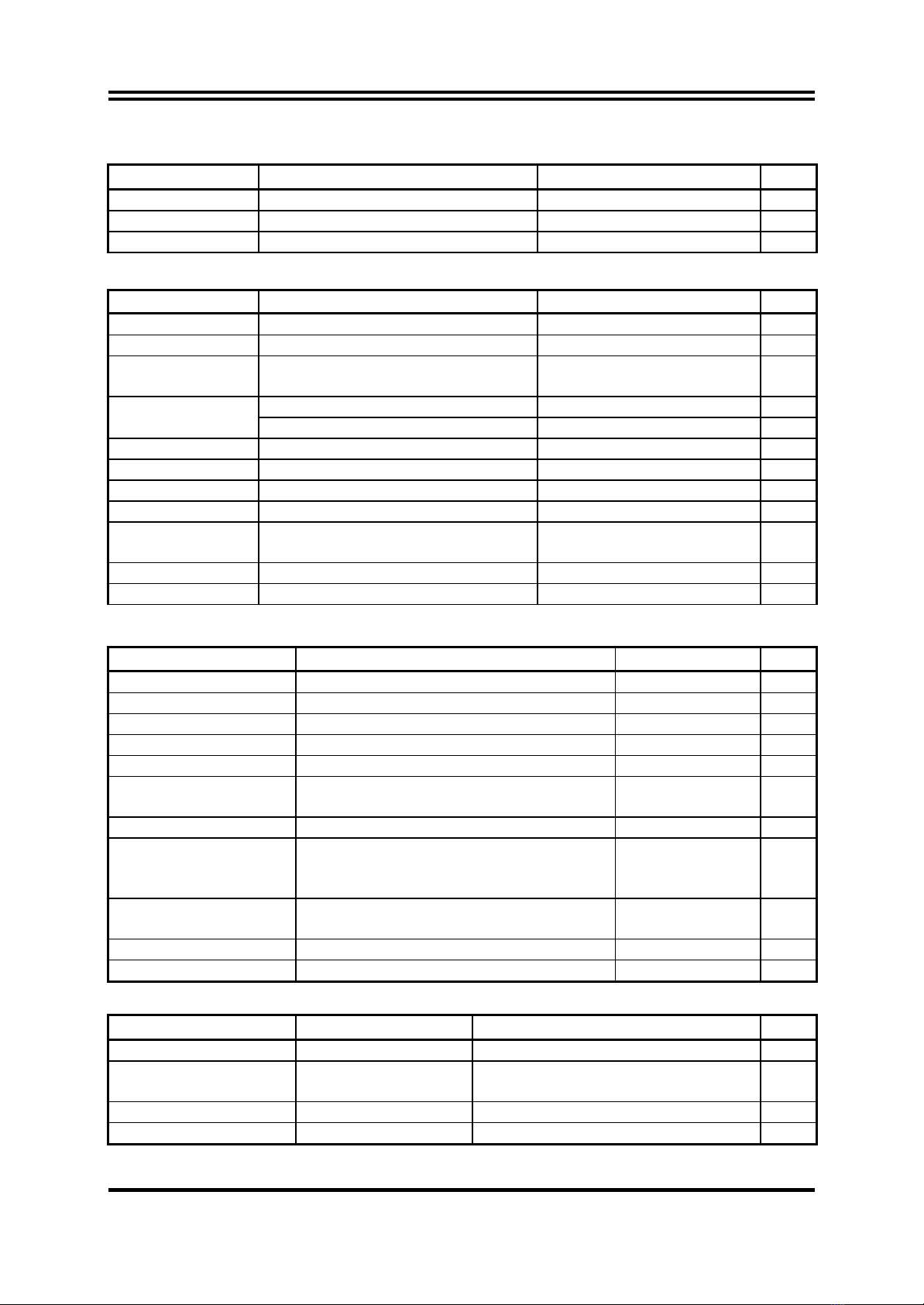
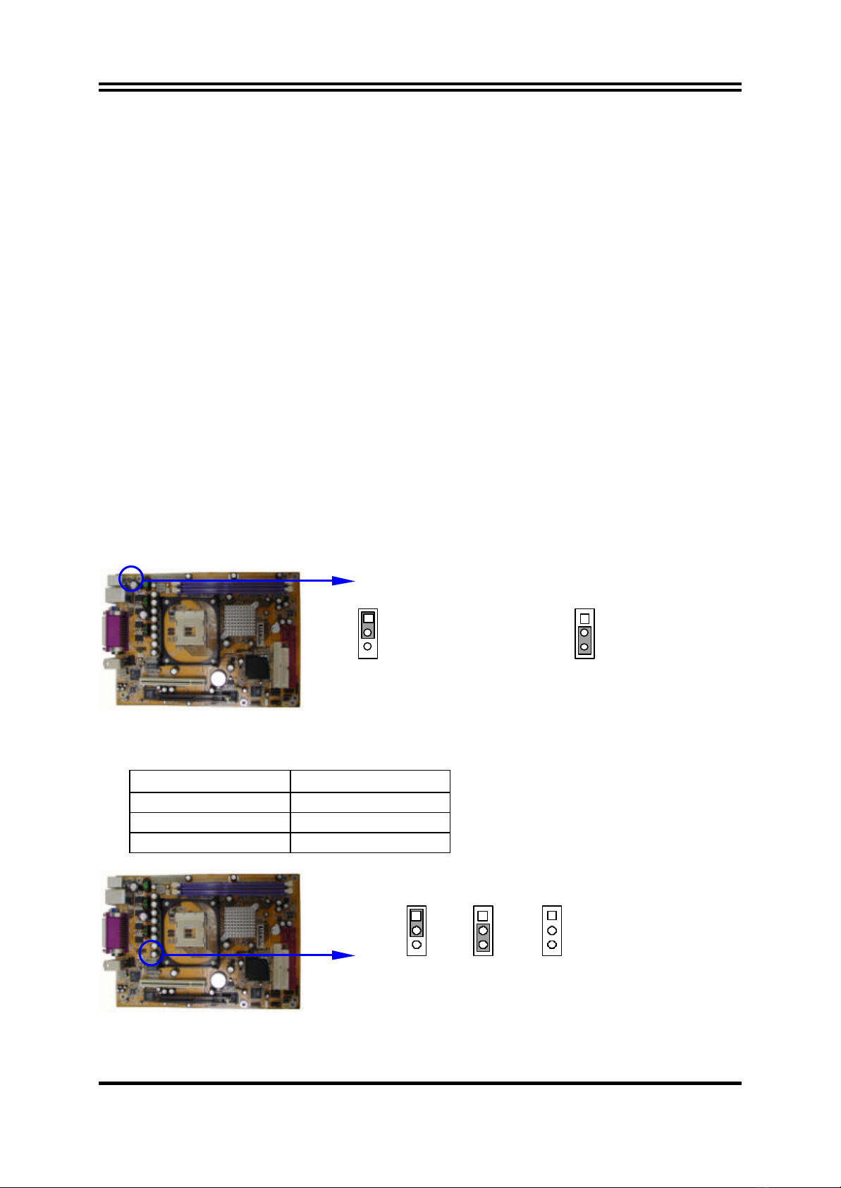
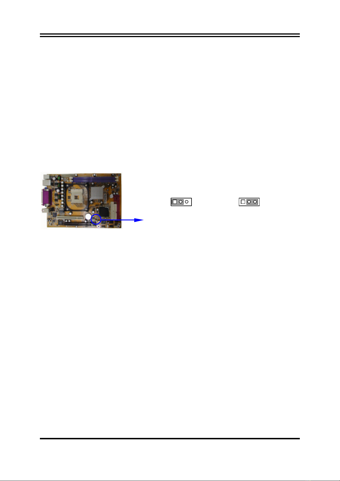
2-2CHECKING MOTHERBOARD'S JUMPER SETTING................................................... 6
2-3INSTALL CPU....................................................................................................... 7
2-3-1 GLOSSARY................................................................................................ 7
2-3-2 ABOUT INTEL PENTIUM 4 478-PIN CPU...................................................... 8
2-4INSTALL MEMORY............................................................................................... 9
2-5EXPANSION CARD .............................................................................................. 9
2-5-1 PROCEDURE FOR EXPANSION CARD INSTALLATION.................................. 10
2-5-2 ASSIGNING IRQ FOR EXPANSION CARD.................................................... 10
2-5-3 INTERRUPT REQUEST TABLE FOR THIS MOTHERBOARD.............................. 10
2-5-4 AGP SLOT................................................................................................. 11
2-6CONNECTORS, HEADERS..................................................................................... 11
2-6-1 CONNECTORS.......................................................................................... 11
2-6-2 HEADERS.................................................................................................. 14
2-7STARTING UP YOUR COMPUTER......................................................................... 17
CHAPTER 3 INTRODUCING BIOS
3-1ENTERING SETUP................................................................................................. 18
3-2GETTING HELP .................................................................................................... 18
3-3THE MAIN MENU................................................................................................ 19
3-4STANDARD CMOS FEATURES............................................................................... 20
3-5ADVANCED BIOS FEATURES ................................................................................ 21
3-6ADVANCED CHIPSET FEATURES ........................................................................... 23
3-6-1 DRAM TIMING SETTINGS.......................................................................... 24
3-7INTEGRATED PERIPHERALS................................................................................... 25
3-7-1 ONBOARD IDE FUNCTION....................................................................... 25
3-7-2 ONBOARD DEVICE FUNCTION................................................................. 26
3-7-3 ONBOARD SUPER IO FUNCTION.............................................................. 27
3-8POWER MANAGEMENT SETUP............................................................................. 28
3-8-1 PM TIMER RELOAD EVENTS ...................................................................... 29
3-9PNP/PCI CONFIGURATION SETUP........................................................................ 29
3-9-1 IRQ RESOURCES....................................................................................... 30
3-10 PC HEALTH STATUS............................................................................................ 31
3-11 MISCELLANEOUS CONTROL............................................................................... 32
3-12 LOAD STANDARD/OPTIMIZED DEFAULTS ........................................................... 33
3-13 SET SUPERVISOR/USER PASSWORD ..................................................................... 33
CHAPTER 4 DRIVER & FREE PROGRAM INSTALLATION
MAGIC INSTALL SUPPORTS WINDOWS 98SE/ME/NT4.0/2000/XP..................................... 34
4-1 INF INSTALL INTEL 845 CHIPSET SYSTEM DRIVER ............................. 35
4-2 VGA INSTALL INTEL 845G VGA DRIVER ............................................ 36
4-3 SOUND INSTALL ALC AUDIO CODEC DRIVER....................................... 36
4-4 LAN INSTALL RTL810X LAN CONTROLLER DRIVER............................ 37
4-5 PC-HEALTH INTEL 845 PC-HEALTH MONITOR.................................................... 38
4-5-1 HOW TO UTILIZE PC-HEALTH................................................................... 39
4-6 MAGIC BIOS INSTALL BIOS LIVE UPDATE UTILITY......................................... 39
4-7 IAA INSTALL INTEL APPLICATION ACCELERATOR SOFTWARE........... 41
4-8 PC-CILLIN INSTALL PC-CILLIN2002 ANTI-VIRUS PROGRAM........................ 41
4-9 HOW TO INSTALL USB 2.0 DRIVER ...................................................................... 42
4-10 HOW TO DISABLE ON-BOARD SOUND ............................................................... 43
4-11 HOW TO UPDATE BIOS....................................................................................... 43
TABLE OF CONTENT

ii
USER’S NOTICE
COPYRIGHT OF THIS MANUAL BELONGS TO THE MANUFACTURER. NO PART OF THIS MANUAL,
INCLUDING THE PRODUCTS AND SOFTWARE DESCRIBED IN IT MAY BE REPRODUCED, TRANSMITTED
OR TRANSLATED INTO ANY LANGUAGE IN ANY FORM OR BY ANY MEANS WITHOUT WRITTEN
PERMISSION OF THE MANUFACTURER.
THIS MANUAL CONTAINS ALL INFORMATION REQUIRED TO USE 845GEFC MOTHER-BOARD AND WE
DO ASSURE THIS MANUAL MEETS USER’S REQUIREMENT BUT WILL CHANGE, CORRECT ANY TIME
WITHOUT NOTICE. MANUFACTURER PROVIDES THIS MANUAL “AS IS” WITHOUT WARRANTY OF ANY
KIND, AND WILL NOT BE LIABLE FOR ANY INDIRECT, SPECIAL, INCIDENTIAL OR CONSEQUENTIAL
DAMAGES (INCLUDING DAMANGES FOR LOSS OF PROFIT, LOSS OF BUSINESS, LOSS OF USE OF DATA,
INTERRUPTION OF BUSINESS AND THE LIKE).
PRODUCTS AND CORPORATE NAMES APPEARING IN THIS MANUAL MAY OR MAY NOT BE REGISTERED
TRADEMARKS OR COPYRIGHTS OF THEIR RESPECTIVE COMPANIES, AND THEY ARE USED ONLY FOR
IDENTIFICATION OR EXPLANATION AND TO THE OWNER’S BENEFIT, WITHOUT INTENT TO INFRINGE.
Manual Revision Information
Reversion Revision History Date
1.0 First Release April 2003
Item Checklist
R845GEFC Motherboard
RCable for IDE/Floppy
RCD for motherboard utility
R845GEFC User’s Manual
Intel Pentium 4 Processor Family
Cooling Solutions
As processor technology pushes to faster speeds and higher performance, thermal management
becomes increasingly crucial when building computer systems. Maintaining the proper thermal
environment is key to reliable, long-term system operation. The overall goal in providing the proper
thermal environment is keeping the processor below its specified maximum case temperature.
Heatsinks induce improved processor heat dissipation through increased surface area and
concentrated airflow from attached fans. In addition, interface materials allow effective transfers
of heat from the processor to the heatsink. For optimum heat transfer, Intel recommends the use of
thermal grease and mounting clips to attach the heatsink to the processor.
When selecting a thermal solution for your system, please refer to the website below for collection
of heatsinks evaluated and recommended by Intel for use with Intel processors. Note, those
heatsinks are recommended for maintaining the specified Maximum T case requirement. In
addition, this collection is not intended to be a comprehensive listing of all heatsinks that support
Intel processors.
For vendor list of heatsink and fan, pleasevisit :
http://developer.intel.com/design/Pentium4/components/index

1
Chapter 1
Introduction of 845GEFC Motherboard
1-1Feature of motherboard
The 845GEFC motherboard is design for use Intel Pentium 4 Processor in 478 Pin Package/
Northwood Processor with the Intel 845GE Chipset delivers a high performance and
professional desktop platform solution. Which utilize the Socket 478 design (Support Hyper
Threading CPU) and the memory size expandable to 2.0GB.
The motherboard use the newest Intel 845GE Chipset Supports 533MHz System Bus in data
transfer rate, the 845GEFC provided 166MHz SDRAM clock frequency support DDR333
SDRAM. The motherboard offers ULTRA ATA 100 to provide speedier HDD throughout
that boosts overall system performance.
845GEFC with integrated 2D/3D GraphicsAccelerator which supports 256 bit graphics core, and
supports hardware motion compensation assist for software MPEG/DVD decode, makes this
board lower cost alternative to a video card. For those wanting even greater graphic performance,
an AGP 4X slot is included on the board (For 1.5V AGP card only. No for 3.3V or Universal
AGP card). This AGP slot will support either a 4X VGA card or Intel Digital Video Out ports add
support for digital displays and TV-out.
The 845GEFC motherboard including PCI LAN Controller chip support 10/100 Mb/sec
Base transfer rate.
The motherboard also has an integrated AC97’ 6-channel Codec on board support 6-channel
3D surround positioning Audio which is fully compatible with Sound Blaster Prothat gives
you the best sound quality and compatibility. The motherboard provided SPDIF-In/ SPDIF-
Out optical function support SPDIF device.
The 845GEFC including the 1394 PCI controller provided 100M/200M/400Mb bandwidth
support two 1394 device port, which compliant with IEEE 1394A-2000 standard.
With USB control as well as capability of expanding to 6 USB2.0 function ports, the
motherboard meet future USB demand also the motherboard have built-in hardware monitor
function. This will monitor and protect your computer. The motherboard special design in
hardware to protect BIOS from virus crash BIOS data.
The motherboard provide special function in BIOS Setup to setting CPU Host clock step by
step increasing let users to approach over clocking. This motherboard provided over current
and over voltage protect function for protection AGP Card and DRAM module, when the
over current or over voltage occurs it will shut down the power immediately to protect
motherboard. Users must turn off the AC power few seconds before turn on system.
The motherboard provided high performance & meet future specification demand. It is
really wise choice for your computer.

2
1-2Specification
Spec Description
Design ∗ ATX form factor 6layers PCB size: 17.5x24.0cm
Chipset ∗ Intel 845GE Graphics Memory Controller Hub (GMCH)
∗ Intel 82801DB I/O Controller Hub (ICH4) Chipset
CPU Socket
(mPGA478B Socket) ∗ Support Intel Pentium 4 478 Pin package utilizes Flip-Chip
Pin Grid Array (FC-PGA2) package processor
∗ Support CPU Frequency 400MHz & 533MHz
∗ Support 1.5G∼3.06G 478 Pin Pentium 4 processor, Support
Hyper Threading
∗ Reserves support for future Intel Pentium 4 processors
Memory Socket ∗ 184-pin DDR SDRAM module socket x2
∗ Support DDR200/DDR266/DDR333 DDR SDRAM
∗ Expandable to 2.0GB
Expansion Slot &
Headers ∗ AGP slot x1 for AGP 1
.5V standard only, support AGP 2.0 &
4X mode
∗ 32-bit PCI slot x 1
Integrate IDE ∗ Two PCI IDE controllers support PCI Bus Mastering, ATA
PIO/DMA and the ULTRA DMA 33/66/100 functions that
deliver the data transfer rate up to 100 MB/s
1394 Port
∗ VIA VT6307S
1394 Controller chip provided two 1394 device
ports support 100/200/400Mb bandwidth
∗ Compliant with IEEE 1394A-2000 standard
LAN On Board
∗ Realtek RTL8101L PCI LAN Controller chip
∗ Supports 10/100 Mb/sec data transfer rate
Integrate VGA ∗ Integrated High Performance & High Quality 3D Accelerator
∗ Support Ultra-AGPII with 2GB/s bandwidth
∗ Built-in programmable 24-bit true-color RAMDAC up to
333MHz pixel clock
∗ Programmable frame buffer size from 8MB and up to 64MB.
Audio ∗ Realtek ALC 650 6-channel AC97’ Codec integrated
∗ SPDIF-In/ SPDIF-Out Optical support
∗ Audio driver and utility included
BIOS ∗ Award 2MB Flash ROM
Multi I/O ∗ PS/2 keyboard and PS/2 mouse connectors
∗ Floppy disk drive connector x1
∗ Parallel port x1, Serial port x2
∗ USB 2.0 connector x2
∗ USB 2.0 headers x2 (connecting cable option)
∗ Audio connector Line-in, Line-out, MIC

3
1-3Performance List
The following performance data list is the testing result of some popular benchmark testing
programs. These data are just referred by users, and there is no responsibility for different
testing data values gotten by users (the different Hardware & Software configuration will
result in different benchmark testing results.)
Performance Test Report
CPU: Intel Pentium 4 2.53GHz mPGAB package
DRAM: 256MB DDR333 SDRAM x1 (MICRON MT46V16M8-6)
VGA Expansion Card: NVDIA Geforce4 TI4400-128MB (1024x768 Hi-color)
Hard Disk Driver: IBM IC35L040AVVN07-0 (ATA-100)
BIOS: Award Optimal default
OS: Win 98SE
On Board VGA
133/166
3D Mark 2000 3792
3D Mark 2001SE 1854
3D Winbench 2000 83.9
PC Mark 2002
CPU/Memory/HDD 6110/5168/1214
Content Creation Winstone 2001 70.9
Content Creation Winstone 2002 28.1
Business Winstone 2001 66.4
Winbench 99:
CPU Mark 99 157
FPU Winmark 99 8890
Business Disk Winmark99 8430
Hi-end Disk Winmark99 26200
Business Graphic Winmark 435
Hi-end Graphic Winmark 1440
SYS Mark 2000/2001 : SISMark 2000/2001 Rating (Internet Content Creation /
Office Productivity)
SISMark 2000
SISMark 2001
SISOFT Sandra 2002 :
Dhrystone ALU MIPS 4774
Whetstone FPU MFLOPS 1518/3130
RAM Int Buffered iSSE2 MB/S 2390
RAM Float Buffered iSSE2
MB/S 2302
Integer SSE2 IT/S 10061
Floating-Point SSE2 IT/S 12269
QUAKE3 DEMO1 FPS 121.1
DEMO2 FPS 121.3
WCPUID System / CPU Clock 134.00/2545.93

4
1-4Layout Diagram & Jumper Setting
PRINT 6-Channel Speaker
PS/2 Mouse
PS/2 Keyboard
LAN
DIMM Socket X2
Floppy Connector
Intel 82845GE Chip
ATA 100 IDE Conn.
Front Panel Conn.
ATX Power Conn.
USB Port
2MBit Flash ROM BIOS
Intel 82801DB Chip
IR Connector
Clear CMOS (JP3)
1394 Port
Connector
VGAUSB SPDIF-OUT
Winbond 83627HF Chip
AC97’ Codec
AGP Slot
PCI Slot
Serial Port COM1
SFAN2
Front Panel Audio Conn.
Speaker Connector
SPDIF-In header
External Remote Control (JP5)
PC99 Back Panel
CPU Socket
CD In Audio
K/B Power ON Jumper
(JP1)
6-Channel Speaker
CPU FAN
USB Port/LAN Connector
PS2 KB/Mouse Port
CPU Frequency Select (JP2)
Serial Port COM2
ATX 12V Power Conn.
SFAN1
SPDIF-Out Optical Conn.
(OPT)
Center/Base
REAR Speaker
Front Speaker

5
Jumpers
Jumper Name Description Page
JP1 Keyboard Power On Enable/Disabled 3-pin Block P.6
JP2 CPU Frequency Select 3-pin Block P.6
JP3 CMOS RAM Clear 3-pin Block P.7
Connectors
Connector Name Description Page
ATXPWR ATX Power Connector 20-pin Block P.11
ATX12V ATX 12V Power Connector 4-pin Block P.12
KB/MOUSE
(PS2 KB/MOUSE) PS/2 Mouse & PS/2 Keyboard
Connector 6-pin Female P.12
USBLAN USB Port Connector 4-pin Connector P.12
LAN Connectors RJ-45 Connector P.12
PARALL Parallel Port Connector 25-pin Female P.12
CN1 Audio Connector 3 phone jack Connector P.12
VGA VGA Display Connector 15-pin Female Connector P.12
COM_2Serial Port COM2 Connector 9-pin Connector P.12
OPT SPDIF-Out Optical Connector Optical Transmitter
Connector P.12
FDD Floppy Driver Connector 34-pin Block P.13
IDE1/IDE2 Primary/Secondary IDE Connector 40-pin Block P.13
Headers
Header Name Description Page
COM1/COM2 Serial Port COM1/COM2 Headers 9-pin Block P.14
FPAUDIO Front Panel Speaker, MIC Headers 5-pin Block P.14
USB1/USB2 USB Port Headers 9-pin Block P.14
1394A/1394B 1394 Port Headers 9-pin Block P.14
SPDIF SPDIF-In (Receiver) Optical Header 3-pin Block P.14
JP5 External Remote Control Connect Cable
Header 2x5-pin Block P.15
SPEAK PCSpeaker connector 4-pin Block P.15
FP
(Power LED/Reset/
IDE LED/ Power Button)
Front Panel Header
(including Power LED/ IDE activity LED/
Reset switch / Power On Button lead)
9-pin Block P.15
SFAN1, SFAN2,
CPUFAN FAN Speed Headers 3-pin Block P.16
IRIR infrared module Headers 5-pin Block P.16
CDIN CD Audio-In Headers 4-pin Block P.16
Expansion Sockets
Socket/Slot Name Description Page
ZIF Socket 478 CPU Socket 478-pin mPGAB CPU Socket P.8
DDR1, DDR2 DDR Module Socket 184-pin DDR SDRAM Module
Expansion Socket P.9
PCI1 PCI Slot 32-bit PCI Local Bus Expansion slots P.9
AGP AGP 4X Mode Slot AGP Expansion Slot P.11

6
Chapter 2
Hardware installation
2-1Hardware installation Steps
Before using your computer, you had better complete the following steps:
1. Check motherboard jumper setting
2. Install CPU and Fan
3. Install System Memory (DIMM)
4. Install Expansion cards
5. Connect IDE and Floppy cables, Front Panel /Back Panel cable
6. Connect ATX Power cable
7. Power-On and Load Standard Default
8. Reboot
9. Install Operating System
10. Install Driver and Utility
2-2Checking Motherboard’s Jumper Setting
(1) Keyboard Power On function Enabled/Disabled (3-pin): JP1
When setting Enabled you can using keyboard by key in password to power on system.
Keyboard Power On Setting
2-3 closed K/B Power ON Enabled
JP1 1
3
JP1 1
3
1-2 closed K/B Power ON Disable
(Default)
(2) CPU Frequency Select (3-pin): JP2
CPU Select JP2
AUTO 1-2 closed (Default)
100 MHz 2-3 closed
133 MHz Empty
CPU Frequency Select
100MHz
JP2
1
3
JP2
1
3
AUTO 133MHz
JP2
1
3
(Default)

7
(3) CMOS RAM Clear (3-pin): JP3
A battery must be used to retain the motherboard configuration in CMOS RAM short 1-
2 pins of JP3 to store the CMOS data.
To clear the CMOS, follow the procedure below:
1. Turn off the system and unplug the AC power
2. Remove ATX power cable from ATX power connector
3. Locate JP3 and short pins 2-3 for a few seconds
4. Return JP3 to its normal setting by shorting pins 1-2
5. Connect ATX power cable back to ATX power connector
Note: When should clear CMOS
1. Troubleshooting
2. Forget password
3. After over clocking system boot fail
CMOS RAM Clear Setting
2-3 closed Clear CMOS
JP3 13
JP3
13
1-2 closed Normal (Default)
2-3Install CPU
2-3-1 Glossary
Chipset (or core logic) -two or more integrated circuits which control the interfaces
between the system processor, RAM, I/O devises, and adapter cards.
Processor slot/socket -the slot or socket used to mount the system processor on the
motherboard.
Slot (AGP, PCI, ISA, RAM) -the slots used to mount adapter cards and system RAM.
AGP -Accelerated Graphics Port -a high speed interface for video cards; runs at 1X
(66MHz), 2X (133MHz), or 4X (266MHz).
PCI -Peripheral Component Interconnect -a high speed interface for video cards, sound
cards, network interface cards, and modems; runs at 33MHz.
ISA -Industry Standard Architecture -a relatively low speed interface primarily used for
sound cards and modems; runs at approx. 8MHz.
Serial Port -a low speed interface typically used for mouse and external modems.
Parallel Port -a low speed interface typically used for printers.
PS/2 -a low speed interface used for mouse and keyboards.
USB -Universal Serial Bus -a medium speed interface typically usedfor mouse, keyboards,
scanners, and some digital cameras.
Sound (interface) -the interface between the sound card or integrated sound connectors and
speakers, MIC, and MIDI sound devices.
LAN (interface) -Local Area Network -the interface to your local area network.

8
BIOS (Basic Input/Output System) -the program logic used to boot up a computer and
establish the relationship between the various components.
Driver -software, which defines the characteristics of a device for use by another device or
other software.
Processor -the "central processing unit" (CPU); the principal integrated circuit used for
doing the "computing" in "personal computer"
Front Side Bus Frequency -the working frequency of the motherboard, which is generated
by the clock generator for CPU, DRAM and PCI BUS.
CPU L2 Cache -the flash memory inside the CPU, normally Athlon CPU has 256K or
above, while Duron will have 64K.
2-3-2 About Intel Pentium 4 478-pin CPU
This motherboard provides a 478-pin surface mount, Zero Insertion Force (ZIF) socket,
referred to as the mPGA478B socket supports Intel Pentium 4 processor in the 478 Pin
package utilizes Flip-Chip Pin Grid Array (FC-PGA2) package technology.
The CPU that comes with the motherboard should have a cooling FAN attached to prevent
overheating. If this is not the case, then purchase a correct cooling FAN before you turn on
your system.
WARNING! Be sure that there is sufficient air circulation across the processor’s
heatsink and CPU cooling FAN is working correctly, otherwise it may
cause the processor and motherboard overheat and damage, you may
install an auxiliary cooling FAN, if necessary.
To install a CPU, first turn off your system and remove its cover. Locate the ZIF socket
and open it by first pulling the level sideways away from the socket then upward to a 90-
degree angle. Insert the CPU with the correct orientation as shown below. The notched
corner should point toward the end of the level. Because the CPU has a corner pin for two
of the four corners, the CPU will only fit in the orientation as shown.
CPU ZIF mPGAB Socket
Colden Arrow
mPGA478B
When you put the CPU into the ZIF socket. No force require to insert of the CPU, then
press the level to Locate position slightly without any extra force.

9
2-4Install Memory
This motherboard provides two 184-pin DUAL INLINE MEMORY MODULES (DIMM)
sites for memory expansion available from minimum memory size of 64MB to maximum
memory size of 2.0GB DDR SDRAM.
Valid Memory Configurations
Bank 184-Pin DIMM PCS Total Memory
Bank 0, 1 (DDR1) DDR200/DDR266/DDR333
DDR SDRAM Module X1 64MB∼1.0GB
Bank 2, 3 (DDR2) DDR200/DDR266/DDR333
DDR SDRAM Module X1 64MB∼1.0GB
Total System Memory (Max. 2.0GB) 264MB∼2.0GB
Generally, installing DDR SDRAM modules to your motherboard is very easy, you can
refer to figure 2-4 to see what a 184-Pin DDR200/DDR266/DDR333 DDR SDRAM
module looks like.
DDR1 (BANK0+BANK1)
DDR2 (BANK2+BANK3)
NOTE! When you install DIMM module fully into the DIMM socket the eject tab should be
locked into the DIMM module very firmly and fit into its indention on both sides.
WARNING! For the DDR SDRAM CLOCK is set at 133MHz, use only DDR266-compliant
DDR Modules. When this motherboard operate at 133MHz, most system will not
even boot if non-compliant modules are used because of the strict timing issues, if
your SDR Modules are not DDR266-compliant, set the DDR SDRAM clock to
100MHz to ensure system stability.
2-5Expansion Cards
WARNING! Turn off your power when adding or removing expansion cards or other system
components. Failure to do so may cause severe damage to both your motherboard
and expansion cards.
Figure 2-4

10
2-5-1 Procedure For Expansion Card Installation
1. Read the documentation for your expansion card and make any necessary hardware or
software setting for your expansion card such as jumpers.
2. Remove your computer’s cover and the bracket plate on the slot you intend to use.
3. Align the card’s connectors and press firmly.
4. Secure the card on the slot with the screen you remove above.
5. Replace the computer system’s cover.
6. Set up the BIOS if necessary.
7. Install the necessary software driver for your expansion card.
2-5-2 Assigning IRQs For Expansion Card
Some expansion cards need an IRQ to operate. Generally, an IRQ must exclusively assign
to one use. In a standard design, there are 16 IRQs available but most of them are already
in use.
Standard Interrupt Assignments
IRQ Priority Standard function
0N/A System Timer
1N/A Keyboard Controller
2N/A Programmable Interrupt
3 * 8Communications Port (COM2)
4 * 9Communications Port (COM1)
5 * 6Sound Card (sometimes LPT2)
6 * 11 Floppy Disk Controller
7 * 7Printer Port (LPT1)
8N/A System CMOS/Real Time Clock
9 * 10 ACPI Mode when enabled
10 * 3IRQ Holder for PCI Steering
11 * 2IRQ Holder for PCI Steering
12 * 4PS/2 Compatible Mouse Port
13 N/A Numeric Data Processor
14 * 5Primary IDE Channel
15 * 1Secondary IDE Channel
* These IRQs are usually available for ISA or PCI devices.
2-5-3 Interrupt Request Table For This Motherboard
Interrupt request are shared as shown the table below:
INT A INT B INT C INT D INT E INT F INT G INT H
Slot 1
√
Onboard VGA
√
Onboard LAN
√
Onboard USB 1
√
Onboard USB 2
√
Onboard USB 3
√
Sound
√
IMPORTANT! If using PCI cards on shared slots, make sure that the drivers support
“Shared IRQ” or that the cards don’t need IRQ assignments. Conflicts will
arise between the two PCI groups that will make the system unstable or
cards inoperable.

11
2-5-4 AGP Slot
This motherboard provides an AGP Slot, only support the 1.5V 4X AGP VGA card.
Do not use AGP 2X card (3.3V) in this motherboard. It will burn and damage the
motherboard due to Intel® 845 chipset can not support AGP 2X (3.3V).
The AGP Slot also supports AGP Digital Display Card for digital display and TV-out.
IMPORTANT! Before you plug-in AGP card, please make sure the following notice is fully
understood and practiced. If your AGP card has “AGP 4X notch (show below)
please make sure your AGP card is AGP 4X (1.5V) not AGP 2X (3.3V)
AGP SLOT
Example 1: SiS 305 & ATi Rage 128 Pro AGP card those golden finger is compatible with
2X/4X mode AGP slot, but only can support 2X (3.3V) only. If you install these
cards in Intel® 845 based motherboard it will burn and damage the motherboard.
Example 2: We also find Diamond Vipper V770 golden finger is design for 2X/4X mode
AGP Slot. It can be adjusted the jumper for AGP 2X (3.3V) or AGP 4X (1.5V).
But the factory default setting is 2X (3.3V). If you install this AGP card in
motherboard without change the jumper setting to 4X (1.5V), it will burn the
motherboard.
2-6Connectors, Headers
2-6-1 Connectors
(1) Power Connector (20-pin block) : ATXPWR
ATX Power Supply connector. This is a new defined 20-pins connector that usually comes
with ATX case. The ATX Power Supply allows to use soft power on momentary switch that
connect from the front panel switch to 2-pins Power On jumper pole on the motherboard.
When the power switch on the back of the ATX power supply turned on, the full power will
not come into the system board until the front panel switch is momentarily pressed. Press
this switch again will turn off the power to the system board.
PIN ROW2 ROW1
1 3.3V 3.3V
2 -12V 3.3V
3 GND GND
4 Soft Power On 5V
5 GND GND
6 GND 5V
7 GND GND
8 -5V Power OK
9 +5V +5V (for Soft Logic)
10 +5V +12V
Pin 1
2x notch 4x notch

12
(2) ATX 12V Power Connector (4-pin block) : ATX12V
This is a new defined 4-pins connector that usually comes with ATX Power Supply.
The ATX Power Supply which fully support Pentium 4 processor must including this
connector for support extra 12V voltage to maintain system power consumption.
Without this connector might cause system unstable because the power supply can not
provide sufficient current for system.
Pin 1
(3) PS/2 Mouse & PS/2 Keyboard Connector: KB/MOUSE
The connectors for PS/2 keyboard and PS/2 Mouse.
(4) USB Port connector: USB
The connectors are 4-pin connector that connect USB devices to the system board.
(5) LAN Port connector: LAN
This connector is standard RJ45 connector for Network connector.
(6) Parallel Port Connector (25-pin female): PARALL
Parallel Port connector is a 25-pin D-Subminiature Receptacle connector. The On-board
Parallel Port can be disabled through the BIOS SETUP. Please refer to Chapter 3
“INTEGRATED PERIPHERALS SETUP” section for more detail information.
(7) Audio Connector : CN1
This Connector are 3 phone Jack for LINE-OUT, LINE-IN, MIC .
Line-out (Green): Audio output to speaker for Front Speaker output in 6-Channel
Line-in (Blue): Audio input to sound chip or REAR Speaker output in 6-Channel
MIC (Pink): Microphone Connector or Center/Base Speaker output in 6-Channel
(8) VGA Connector (15-pin D-Sub) Connector: VGA
VGA is the 15-pin D-Subminiature female connector for display monitor.
(9) Serial Port2 COM2: COM_2
COM_2 is the 9-pin D-Subminiature mail connector. The On-board serial port can be
disabled through BIOS SETUP. Please refer to Chapter 3 “INTEGRATED PERIPHERALS
SETUP” section for more detail information.
(10) SPDIF-Out Optical Connector : OPT
Optical Transmitter Connector for SPDIF Speaker or SPDIF device .
PS/2
Keyboard VGAUSB
PS/2
Mouse
SPDIF-OUT
PRINT 6-Channel SpeakerLAN
Center/Base
REAR Speaker
Front Speaker

13
(11) Floppy drive Connector (34-pin block): FDD
This connector supports the provided floppy drive ribbon cable. After connecting the single
plug end to motherboard, connect the two plugs at other end to the floppy drives.
Floppy Drive Connector
Pin 1
FDD
(12) Primary IDE Connector (40-pin block): IDE1
This connector supports the provided IDE hard disk ribbon cable. After connecting the single
plug end to motherboard, connect the two plugs at other end to your hard disk(s). If you install
two hard disks, you must configure the second drive to Slave mode by setting its jumpers
accordingly. Please refer to the documentation of your hard disk for the jumper settings.
Primary IDE Connector
Pin 1
IDE1
(13) Secondary IDE Connector (40-pin block): IDE2
This connector connects to the next set of Master and Slave hard disks. Follow the same
procedure described for the primary IDE connector. You may also configure two hard disks
to be both Masters using one ribbon cable on the primary IDE connector and another ribbon
cable on the secondary IDE connector.
Secondary IDE Connector
Pin 1
IDE2
•
Two hard disks can be connected to each connector. The first HDD is referred to as the
“Master” and the second HDD is referred to as the “Slave”.
•
For performance issues, we strongly suggest you don’t install a CD-ROM or DVD-ROM
drive on the same IDE channel as a hard disk. Otherwise, the system performance on this
channel may drop.

14
2-6-2 Headers
(1) Serial Port COM1/COM2 Header (9-pin) : COM1/COM2
COM1
Pin1
Note: Orient the read marking on the
COM1/COM2 ribbon cable to
pin 1
Serial Port COM1/COM2 Header
COM2
Pin1
(2) Speaker/MIC Header for Front Panel (5-pin): FPAUDIO
This header connect to Front Panel Speaker, MIC connector with cable.
Speaker, MIC Headers
Pin 1
GND
MIC
5VMIC
SPEAKER-R
SPEAKER-L
(3) USB Port Headers (9-pin) : USB1, USB2
These headers are used for connecting the additional USB port plug. By attaching an option
USB cable, your can be provided with two additional USB plugs affixed to the back panel.
USB Port Headers
VCC
USB2
Pin 1
-DATA
GND
+DATA
VCC
OC
-DATA
GND
+DATA
OC (Over Current)
VCC
USB1
Pin 1
-DATA
GND
+DATA
VCC
OC
-DATA
GND
+DATA
(4) 1394 Port Headers (9-pin): 1394A, 1394B
1394 Port Headers
1394A
Pin 1
TPA-
GND
VCC
TPB-
TPA+
GND
GND
VCC
TPB+
1394B
Pin 1
(5) SPDIF-In (Receiver) Optical Header (3-pin) : SPDIF
This header is for SPDIF-In Optical Receiver Connector, by this connector you can in-put
digital signal from other device such like CD-ROM, CD player to get high quality audio.

15
SPDIF-IN Optical Headers
SPDIF
13
VCC5
GND
SPDIF-IN
(6) External Remote Control Connect Cable Header: JP5
JP5 is for connect External Remote Control, when plug out the connect cable you have to
insert the jumpers in 3-5, 7-9, 4-6, 8-10 otherwise the On board Keyboard and Mouse will not
work.
JP5
Pin1
GND
KB-DATA
MS-DATA
EXT-KB-DATA
EXT-MS-DATA
VCC
KB-CLK
MS-CLK
EXT-KB-CLK
EXT-MS-CLK
2
9
10
(7) Speaker connector: SPEAK
This 4-pin connector connects to the case-mounted speaker. See the figure below.
(8) IDE Activity LED: IDE LED
This connector connects to the hard disk activity indicator light on the case.
(9) Reset switch lead: RESET
This 2-pin connector connects to the case-mounted reset switch for rebooting your computer
without having to turn off your power switch. This is a preferred method of rebooting in
order to prolong the lift of the system’s power supply. See the figure below.
(10) Power LED: PWR-LED
The Power LED is light on while the system power is on. Connect the Power LED from the
system case to this pin.
(11) Power switch: PWR BTN
This 2-pin connector connects to the case-mounted power switch to power ON/OFF the system.
System Case Connections
SPEAK
SPKR
GND
NC
VCC5
Pin 1
FP
Pin 1
HDLED
RESET
VCC5
GND
VCC5 ACPILED
PWRBTN
PWRBTN
ACPILED
HDDLED
RSTSW
NC GND

16
(12) FAN Speed Headers (3-pin) : SFAN1, SFAN2, CPUFAN
These connectors support cooling fans of 350mA (4.2 Watts) or less, depending on the fan
manufacturer, the wire and plug may be different. The red wire should be positive, while the
black should be ground. Connect the fan’s plug to the board taking into consideration the
polarity of connector.
CPUFAN
1
3
SFAN2
13
SFAN1
13
(13) IR infrared module Headers (5-pin) : IR
This connector supports the optional wireless transmitting and receiving infrared
module. You must configure the setting through the BIOS setup to use the IR function.
IR infrared module Headers
IR
Pin 1
GND
IRRX
NC
VCC5
IRTX
2
5
6
(14) CD Audio-In Headers (4-pin) : CDIN
CDIN are the connectors for CD-Audio Input signal. Please connect it to CD-ROM
CD-Audio output connector.
CD Audio-In Headers
CDIN 4
1

17
2-7Starting Up Your Computer
1. After all connection are made, close your computer case cover.
2. Be sure all the switch are off, and check that the power supply input voltage is set to
proper position, usually in-put voltage is 220V∼240V or 110V∼120V depending on your
country’s voltage used.
3. Connect the power supply cord into the power supply located on the back of your
system case according to your system user’s manual.
4. Turn on your peripheral as following order:
a. Your monitor.
b. Other external peripheral (Printer, Scanner, External Modem etc…)
c. Your system power. For ATX power supplies, you need to turn on the power supply and
press the ATX power switch on the front side of the case.
5. The power LED on the front panel of the system case will light. The LED on the
monitor may light up or switch between orange and green after the system is on. If it
complies with green standards or if it is has a power standby feature. The system will
then run power-on test. While the test are running, the BIOS will alarm beeps or
additional message will appear on the screen.
If you do not see any thing within 30 seconds from the time you turn on the power. The
system may have failed on power-on test. Recheck your jumper settings and connections
or call your retailer for assistance.
Beep Meaning
One short beep when displaying logo No error during POST
Long beeps in an endless loop No DRAM install or detected
One long beep followed by three short
beeps Video card not found or video card memory
bad
High frequency beeps when system is
working CPU overheated
System running at a lower frequency
6. During power-on, press <Delete> key to enter BIOS setup. Follow the instructions in
BIOS SETUP.
7. Power off your computer: You must first exit or shut down your operating system before
switch off the power switch. For ATX power supply, you can press ATX power switching after
exiting or shutting down your operating system. If you use Windows 9X, click “Start” button,
click “Shut down” and then click “Shut down the computer?” The power supply should turn
off after windows shut down.
Table of contents
Other JETWAY Motherboard manuals

JETWAY
JETWAY M26GT4SVM User manual

JETWAY
JETWAY NAF95-Q87 User manual

JETWAY
JETWAY PM2M - REV 1.0 User manual

JETWAY
JETWAY For Socket 370 User manual

JETWAY
JETWAY NF36-2600 User manual

JETWAY
JETWAY PM800DM User manual

JETWAY
JETWAY 911BF User manual

JETWAY
JETWAY P4MBMS - REV 1.0 User manual

JETWAY
JETWAY MBD-J-JNF9KC-1047 User manual

JETWAY
JETWAY 603TCR1C User manual

JETWAY
JETWAY 845GPR2A User manual

JETWAY
JETWAY P4M2PRO-P User manual

JETWAY
JETWAY S447R3A User manual

JETWAY
JETWAY MI92 User manual

JETWAY
JETWAY NC84 User manual

JETWAY
JETWAY V266DMU User manual

JETWAY
JETWAY S445R1C User manual

JETWAY
JETWAY JNF694 Series User manual

JETWAY
JETWAY 830CF User manual

JETWAY
JETWAY P4845GEB1A User manual