JETWAY NF591 User manual

Technical Manual
Of
Intel Braswell Series CPU
Based Mini-ITX M/B
NO.G03-NF591-F
Revision: 2.0
Release date: October 1, 2019
Trademark:
* Specifications and Information contained in this documentation are furnished for information use only, and are
subject to change at any time without notice, and should not be construed as a commitment by manufacturer.

ii
Environmental Protection Announcement
Do not dispose this electronic device into the trash while discarding. To minimize
pollution and ensure environment protection of mother earth, please recycle.

iii
ENVIRONMENTAL SAFETY INSTRUCTION...........................................................................iv
USER’S NOTICE .......................................................................................................................v
MANUAL REVISION INFORMATION.......................................................................................v
ITEM CHECKLIST.....................................................................................................................v
CHAPTER 1 INTRODUCTION OF THE MOTHERBOARD
1-1 FEATURE OF MOTHERBOARD................................................................................1
1-2 SPECIFICATION.........................................................................................................2
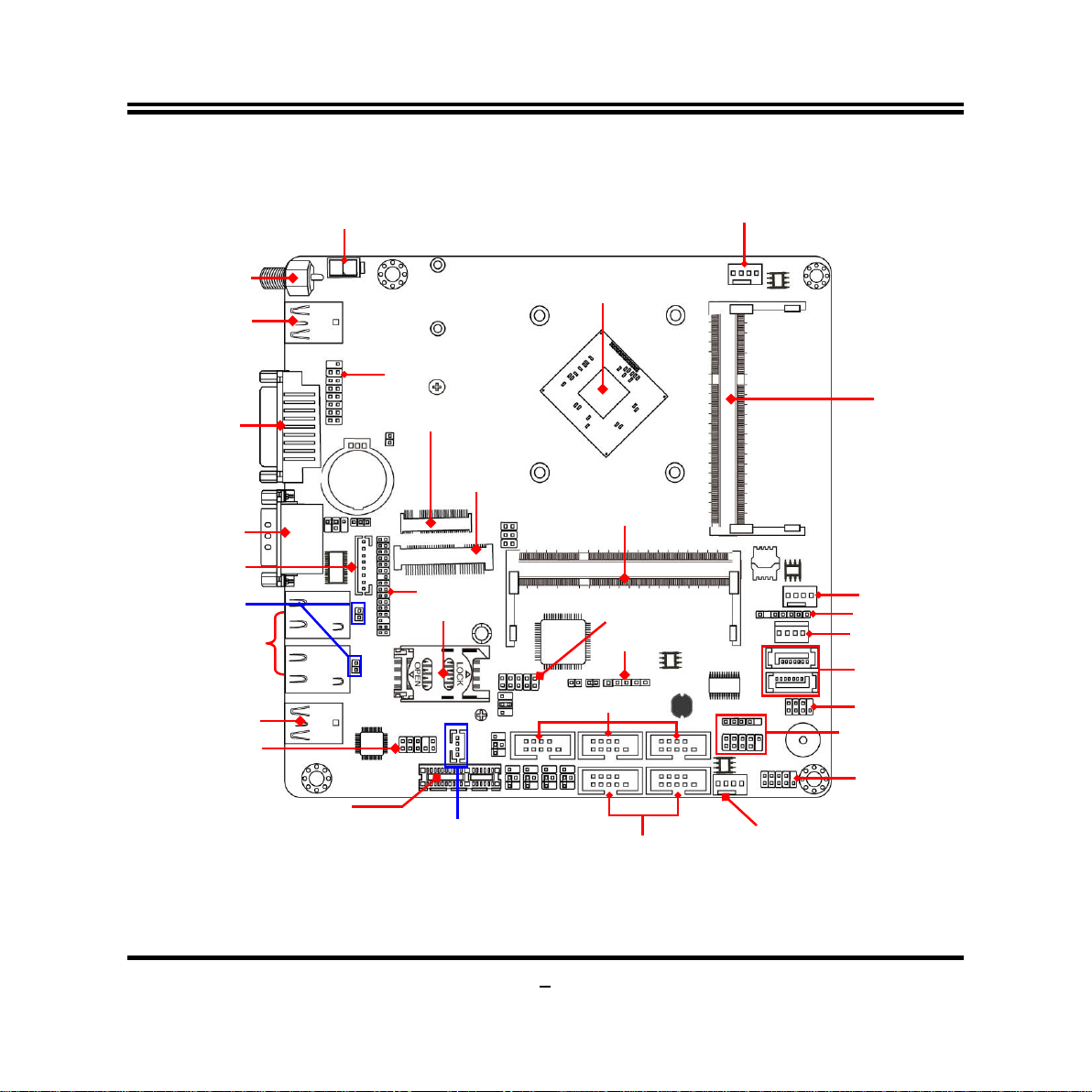
1-3 LAYOUT DIAGRAM....................................................................................................3
CHAPTER 2 HARDWARE INSTALLATION
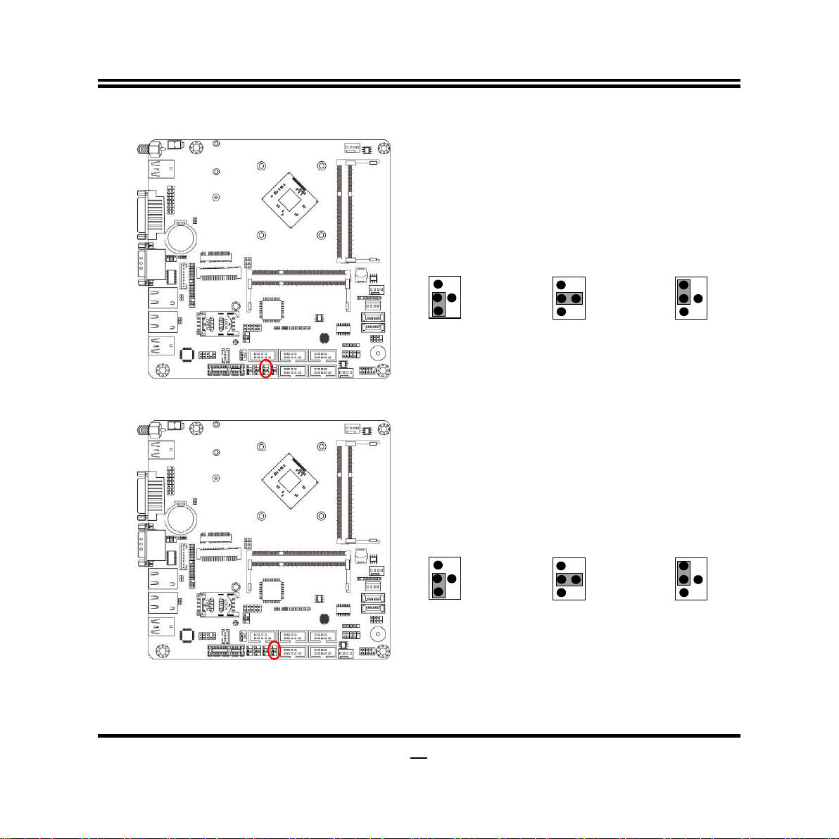
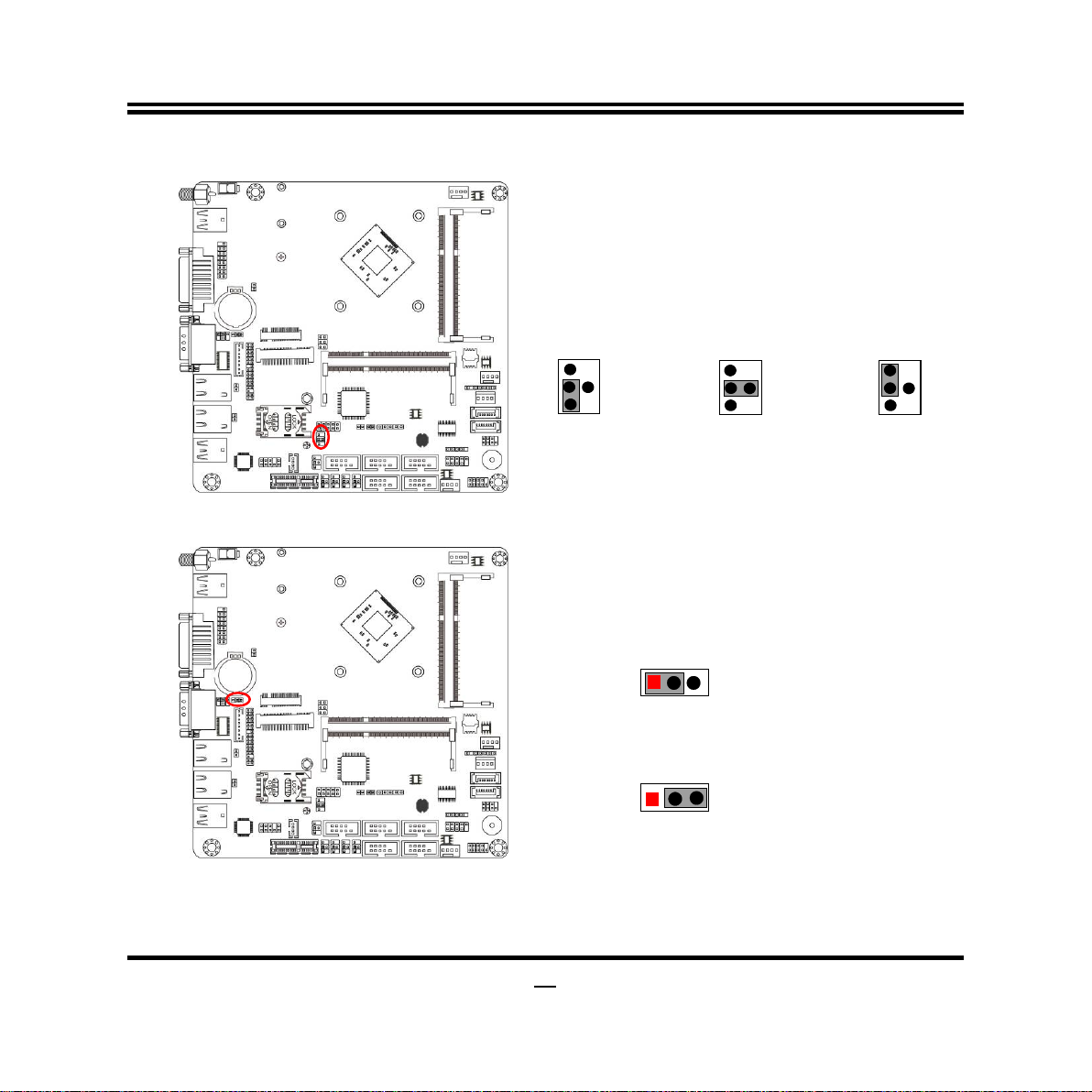
2-1 JUMPER SETTING .....................................................................................................8
2-2 CONNECTORS AND HEADERS................................................................................15
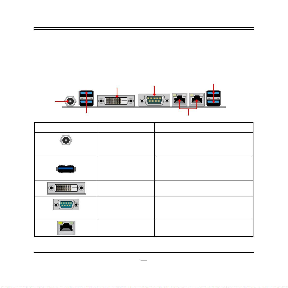
2-2-1 CONNECTORS .............................................................................................15
2-2-2 HEADERS .....................................................................................................18
CHAPTER 3 INTRODUCING BIOS
3-1 ENTERING SETUP .....................................................................................................26
3-2 BIOS MENU SCREEN ................................................................................................27
3-3 FUNCTION KEYS .......................................................................................................27
3-4 GETTING HELP ..........................................................................................................28
3-5 MEMU BARS...............................................................................................................28
3-6 MAIN MENU................................................................................................................29
3-7 ADVANCED MENU.....................................................................................................30
3-8 CHIPSET MENU..........................................................................................................40
3-9 SECURITY MENU.......................................................................................................43
3-10 BOOT MENU...............................................................................................................44
3-11 SAVE & EXIT MENU...................................................................................................45
TABLE OF CONTENT

iv
Environmental Safety Instruction
Avoid the dusty, humidity and temperature extremes. Do not place the product in
any area where it may become wet.
0 to 60 centigrade is the suitable temperature. (The figure comes from the request
of the main chipset)
Generally speaking, dramatic changes in temperature may lead to contact
malfunction and crackles due to constant thermal expansion and contraction from
the welding spots’ that connect components and PCB. Computer should go
through an adaptive phase before it boots when it is moved from a cold
environment to a warmer one to avoid condensation phenomenon. These water
drops attached on PCB or the surface of the components can bring about
phenomena as minor as computer instability resulted from corrosion and oxidation
from components and PCB or as major as short circuit that can burn the
components. Suggest starting the computer until the temperature goes up.
The increasing temperature of the capacitor may decrease the life of computer.
Using the close case may decrease the life of other device because the higher
temperature in the inner of the case.
Attention to the heat sink when you over-clocking. The higher temperature may
decrease the life of the device and burned the capacitor.

v
USER’S NOTICE
COPYRIGHT OF THIS MANUAL BELONGS TO THE MANUFACTURER. NO PART OF THIS MANUAL,
INCLUDING THE PRODUCTS AND SOFTWARE DESCRIBED IN IT MAY BE REPRODUCED, TRANSMITTED
OR TRANSLATED INTO ANY LANGUAGE IN ANY FORM OR BY ANY MEANS WITHOUT WRITTEN
PERMISSION OF THE MANUFACTURER.
THIS MANUAL CONTAINS ALL INFORMATION REQUIRED TO USE THIS MOTHER-BOARD SERIES AND WE
DO ASSURE THIS MANUAL MEETS USER’S REQUIREMENT BUT WILL CHANGE, CORRECT ANY TIME
WITHOUT NOTICE. MANUFACTURER PROVIDES THIS MANUAL “AS IS” WITHOUT WARRANTY OF ANY
KIND, AND WILL NOT BE LIABLE FOR ANY INDIRECT, SPECIAL, INCIDENTIAL OR CONSEQUENTIAL
DAMAGES (INCLUDING DAMANGES FOR LOSS OF PROFIT, LOSS OF BUSINESS, LOSS OF USE OF DATA,
INTERRUPTION OF BUSINESS AND THE LIKE).
PRODUCTS AND CORPORATE NAMES APPEARING IN THIS MANUAL MAY OR MAY NOT BE
REGISTERED TRADEMARKS OR COPYRIGHTS OF THEIR RESPECTIVE COMPANIES, AND THEY ARE
USED ONLY FOR IDENTIFICATION OR EXPLANATION AND TO THE OWNER’S BENEFIT, WITHOUT
INTENT TO INFRINGE.
Manual Revision Information
Reversion Revision History Date
2.0 Second Edition October 1, 2019
Item Checklist
Motherboard
Cable(s)

1
Chapter 1
Introduction of the Motherboard
1-1 Feature of Motherboard
Onboard Intel®Braswell series SoC Processor, with low power consumption
never denies high performance
Support 2* DDR3L 1600 MHz SO-DIMM, up to 8GB
Onboard 2 * RJ-45 gigabit Ethernet LAN port
Support 2 * SATAIII device
Support USB 3.0 data transport demand
Support DVI-D, VGA & LVDS multi-display
Onboard 1* full-size Mini-PCIE slot
Onboard 1* M.2 slot (M key-2242/2260/2280 SATA interface for SSD device)
1* SIM card slot
Support CPU Over-Temperature protection
Support CPU Over-Current/Under Voltage protection
Support DRAM Over-Current/Under Voltage protection
Amplifier implement to support 3W Speaker
Support Smart FAN
Compliance with ErP standard
Support Watchdog function

2
1-2 Specification
Spec
Description
Design
6 layers; PCB size: 17x 17 cm
Embedded CPU
Intel®Braswell *SoC CPU
*CPU model varies from different IPC options. Please consult your
dealer for more information of onboard CPU.
Memory Slot
2 * DDR3L SODIMM Slot for un-buffered *DDR3L 1600 MHz
SDRAM, expandable to 8GB
Dual-channel function supported
Expansion Slot
1* Full-size Mini-PCIE slot
1* PCIE x1 slot
LAN Chip
Integrated with 2* Realtek RTL8111G PCI-E Gigabit LAN chip
Support Fast Ethernet LAN function of providing
10/100/1000Mbps Ethernet data transfer rate
Storage
2* SATAIII port (SATA1/2)
1*M.2 M-key 2242/2260/2280 slot (*share with SATA2 port)
BIOS
AMI 64MB Flash ROM
Rear I/O
1* 12V DC-in system power Jack
4* USB 3.0 port
1* DVI-D port
1* RS232/422/485 serial port (COM1)
2* RJ-45 LAN port
Internal I/O
1* 2-Pin Internal 12V DC-in power connector
1* SATA Power-out connector
1* CPUFAN header
2* SYSFAN header
1* Front panel audio header
1* SPEAK_CON header
2* LAN LED activity header

3
1* 4-pin USB 2.0 header (Expansible to 1* USB 2.0 port)
1* 9-pin USB 2.0 header (Expansible to 2* USB 2.0 ports)
1* Front panel header
1* Power LED & speaker header
1* PS/2 keyboard & mouse header
1* SMBUS header
1* GPIO_CON header
5* RS232 serial port header(COM2/3/4/5/6)
1* LVDS header
1* LVDS inverter header
1* Front panel VGA header
*Note: 1. Many PCs now include XHCI USB controllers which allow for the support of USB 3.0 and higher USB
speeds. This inclusion of XHCI controllers has lessened the need for EHCI USB controllers within platforms.
However, legacy operating systems (OS) may not natively recognize XHCI controllers. You might need to
pre-install XHCI driver while desiring to install a non-xHCI OS (ex.Windows* 7) on Intel platforms which do not
include EHCI controllers. Please contact your representative for more details. 2. Braswell SOC will support
memory speed at 1600 MHz and 1066 MHz only. If 1333 MHz DIMM is installed, it will run at 1066 MHz. It is not
validated while installing 1066MHz DIMM with this SOC.
1-3 Layout Diagram
Rear IO Panel Diagram:
Warning!
The board has a DC 12V power connector (DCIN) in I/O back panel and an internal ATX12V
(ATX2P) power connector. User can only connect one type of compatible power supply to one
of them to power the system.
USB 3.0 Ports
RJ-45 LAN Ports
USB 3.0 Ports
DVI-D Port
COM1
Serial Port
DC-in 12V
Power
Connector

4
Motherboard Internal Diagram
Note: 1. SODIMM1 must be used for single DIMM use case; the module should be 1.35V DDRIII
SODIMM and not exceeding 8GB total capacity. 2. M2 slot shares function with SATA2port; i.e. only
one can function at a time; M2 slot functions as M Key interface and can only support SATA SSD
device, not PCI-E NAND device.
12V DC -in
Power Connector
DVI-D Port
COM1
Serial Port
RJ-45 LAN Ports
USB 3.0 Ports
USB 3.0 Ports
PCI Express x1 Slot
Intel CPU
SYSFAN1 Header
*DDR3L SODIMM Slot
(SODIMM1)
Internal 12V DC-in
Power connector
SMBUS Header
*DDR3L SODIMM Slot
(SODIMM2)
CPUFAN Header
SYSFAN2 Header
VGA Port
Header
PS2KBMS Header
Speaker Header
Front Panel
Audio Header
GPIO Header
SATAIII Ports
(SATA1/2)
M Key-2242/2260/2280
Connector (*M2)
Full-size
Mini-PCIE
Slot (MPE)
*SIM Card Slot
Serial Port Headers
(COM5/6)
USB 2.0 Headers
Serial Port Headers
(COM2/3/4)
LVDS Inverter
LVDS Header
SATA Hard Disk
Power-Out Connector
Front Panel
Header
LANLED Headers
Power LED Header &
Speaker Header

5
Jumper Position:
JP1
JBAT
JP6
JP7
JP8
JP9
JP5
COPEN
AT_MODE
RTC_RST
JP3
JP4

6
Jumper
Jumper
Name
Description
JP1
COM1 Port Pin9 Function Select
4-Pin Block
JP3
COM2 Header Pin9 Function Select
4-Pin Block
JP6
COM3 Header Pin9 Function Select
4-Pin Block
JP7
COM4 Header Pin9 Function Select
4-Pin Block
JP8
COM5 Header Pin9 Function Select
4-Pin Block
JP9
COM6 Header Pin9 Function Select
4-Pin Block
JP5
LVDS Panel VCC 3.3V /5V/12V Select
4-Pin Block
JP4
INVERTER Back Light 5V/12V Select
3-Pin Block
COPEN
Case Open Message Display Function
2-Pin Block
AT_MODE
ATX Mode / AT Mode Select
2-Pin Block
RTC_RST
Reset all RTC register bits
2-Pin Block
JBAT
Pin (1&2): Flash Descriptor Security Override
Pin (3&4): Clear CMOS RAM Function Setting
Pin (5&6): ODD Present Setting
6-Pin Block
Connectors
Connector
Name
DCIN
DC 12V System Power–in Connector
ATX2P
Internal DC 12V System Power–in Connector
USB30/USB31
USB 3.0 Port Connector X2
DVI
DVI-D Port Connector
COM1
Serial Port Connector
LAN1/LAN2
RJ-45 LAN Port Connector X2
SATA1/2
SATAIII Port Connector X2
SATAPW
SATA Power out Connector
CPUFAN
CPUFAN Connector
SYSFAN1/SYSFAN2
SYSFAN Connector X2

7
Headers
Header
Name
Description
FP_AUDIO
Front Panel Audio Header
9-pin Block
SPEAK_CON
Speaker Header
4-pin Block
LAN1_LED/LAN2LED
LAN Activity LED Header
2-pin Block
FP_USB21
USB 2.0 Header
4-pin Block
FP_USB20
USB 2.0 Header
9-pin Block
JW_FP
Front Panel Header(PWR LED/
HDD LED/Power Button /Reset)
9-pin Block
SPK-LED
Power LED & Speaker Header
7-pin Block
PS2KBMS
PS/2 Keyboard & Mouse Header
6-pin Block
SMBUS
SMBUS Header
5-pin Block
GPIO_CON
GPIO Header
10-pin Block
COM2/3/4/5/6
Serial Port Header X5
9-pin Block
LVDS
LVDS Header
30-pin Block
INVERTER
LVDS Inverter
8-pin Block
FP_VGA
Front Panel VGA Header
15-pin Block

8
Chapter 2
Hardware Installation
2-1 Jumper Setting
JP1 (4-pin): COM1 Port Pin9 Function Select
JP1
→
COM1 Port Pin-9
6
4
2
3
1
5
2-4 Closed:
RI=RS232(Default);
3-4 Closed:
RI= 5V;
4-6 Closed:
RI= 12V.
1
3
5
2
4
6
1
3
5
2
4
6
JP3 (4-pin): COM2 Header Pin9 Function Select
JP3
→
COM2 Header Pin-9
4-6 Closed:
RI= +12V.
1
3
5
3-4 Closed:
RI= +5V;
2-4 Closed:
RI=RS232;
4
6
2
6
5
3
1
4
2
5
3
1
6
4
2

9
JP6 (4-pin): COM3 Header Pin9 Function Select
JP6
→
COM3 Header Pin-9
4-6 Closed:
RI= +12V.
1
3
5
3-4 Closed:
RI= +5V;
2-4 Closed:
RI=RS232;
4
6
2
6
5
3
1
4
2
5
3
1
6
4
2
JP7 (4-pin): COM4 Header Pin9 Function Select
JP7
→
COM4 Header Pin-9
4-6 Closed:
RI= +12V.
1
3
5
3-4 Closed:
RI= +5V;
2-4 Closed:
RI=RS232;
4
6
2
6
5
3
1
4
2
5
3
1
6
4
2

10
JP8 (4-pin): COM5 Header Pin9 Function Select
JP8
→
COM5 Header Pin-9
4-6 Closed:
RI= +12V.
1
3
5
3-4 Closed:
RI= +5V;
2-4 Closed:
RI=RS232;
4
6
2
6
5
3
1
4
2
5
3
1
6
4
2
JP9 (4-pin): COM6 Header Pin9 Function Select
JP9
→
COM6 Header Pin-9
4-6 Closed:
RI= +12V.
1
3
5
3-4 Closed:
RI= +5V;
2-4 Closed:
RI=RS232;
4
6
2
6
5
3
1
4
2
5
3
1
6
4
2

11
JP5 (4-pin): LVDS Panel VCC 3.3V/5V/12V Select
JP5
→
LVDS Panel VCC
1
3
5
4
6
2
6
5
3
1
4
2
5
3
1
6
4
2
2-4 Closed:
VCC=3.3V;
3-4 Closed:
VCC= 5V
(Default);
4-6 Closed:
VCC= 12V.
JP4 (3-pin): INVERTER Back Light VCC 5V/12V Select
2-3 Close: INVERTER Back Light 12V Selected(Default).
JP4
→
INVERTER Back Light VCC
1-2 Close: INVERTER Back Light 5V Selected;
1
3
1
3

12
COPEN (2-pin): Case Open Message Display Function Select
COPEN
1-2 Open: Normal(Defualt);
1
1
1-2 Closed: Case Open Function
Selected(One Touch).
Pin 1-2 Close:When Case open function pin short to GND, the Case open function
was detected. When Used, needs to enter BIOS and enable ‘Case Open Detect’
function. In this case if your case is removed,next time when you restart your computer,
a message will be displayed on screen to inform you of this.
AT_MODE (2-pin): ATX Mode/AT Mode Select
1
1
AT_MODE
1-2 Open: ATX Mode Selected;
1-2 Closed:AT Mode Selected.

13
*ATX Mode Selected: Press power button to power on after power input ready;
AT Mode Selected: Directly power on as power input ready.
RTC_RST (2-pin): Reset All RTC Register Bits
RTC_RST
1-2 Close: RTC Reset.
1-2 Open: Normal(Default);
1
1
Pin 1 & 2 of JBAT (6-pin): Flash Descriptor Security Override
Pin 1-2 of JBAT
→
Flash Desciptor Security Override
2
Pin 1
1-2 Open:Normal (Default);
Pin 1
1-2 Closed: Flash Descriptor Security Override.
2

14
Pin 3 & 4 of JBAT (6-pin): Clear CMOS Setting
Pin 3-4 of JBAT
→
Clear CMOS
2
Pin1
Pin1
2
4
3
3
4
3-4 Open: Normal(Default);
3-4 Closed: Clear CMOS(One Touch).
Pin 5&6 of JBAT (6-pin): ODD Present Select
Pin 5-6 of JBAT
→
ODD Present Select
2
Pin1
Pin1
2
4
3
3
4
5-6 Open: Normal (Default);
5-6 Closed: ODD Present.
5
6
5
6

15
2-2 Connectors and Headers
2-2-1 Connectors
(1) Rear I/O Connectors
Icon Name Function
12V DC-in Power
Connector
For user to connect compatible power
adapter to provide power supply for the
system.
USB 3.0 Port To connect USB keyboard, mouse or other
devices compatible with USB specification.
USB 3.0 ports supports up to 5Gbps data
transfer rate.
DVI-D Port To connect display device that support DVI
specification.
COM1:
RS232/422/485
Serial Port
Mainly for user to connect external MODEM
or other devices that supports
Serial Communications Interface.
RJ-45 LAN Port This connector is standard RJ-45 LAN jack
for Network connection.
USB 3.0 Ports
RJ-45 LAN Ports
USB 3.0 Ports
DVI-D Port
COM1
Serial Port
DC-in 12V
Power
Connector
Table of contents
Other JETWAY Motherboard manuals

JETWAY
JETWAY R3399X-2C Series User manual

JETWAY
JETWAY 917PDCPR106 User manual

JETWAY
JETWAY MI23 Series User manual

JETWAY
JETWAY 815EDA1A User manual

JETWAY
JETWAY G03-NF96-F User manual

JETWAY
JETWAY V6FP User manual

JETWAY
JETWAY MI92 User manual

JETWAY
JETWAY V333DAR1C User manual

JETWAY
JETWAY P4XFAR5A User manual

JETWAY
JETWAY 917GBAR3A User manual

JETWAY
JETWAY 627FWE User manual

JETWAY
JETWAY MM91 Series User manual

JETWAY
JETWAY NF9G-QM77 User manual

JETWAY
JETWAY NU95 Series User manual

JETWAY
JETWAY 650DFR1A User manual

JETWAY
JETWAY 845LDA1A User manual

JETWAY
JETWAY NF9A-Q67 User manual

JETWAY
JETWAY 635CSR1A User manual

JETWAY
JETWAY MCP78S User manual

JETWAY
JETWAY NF632E Series User manual