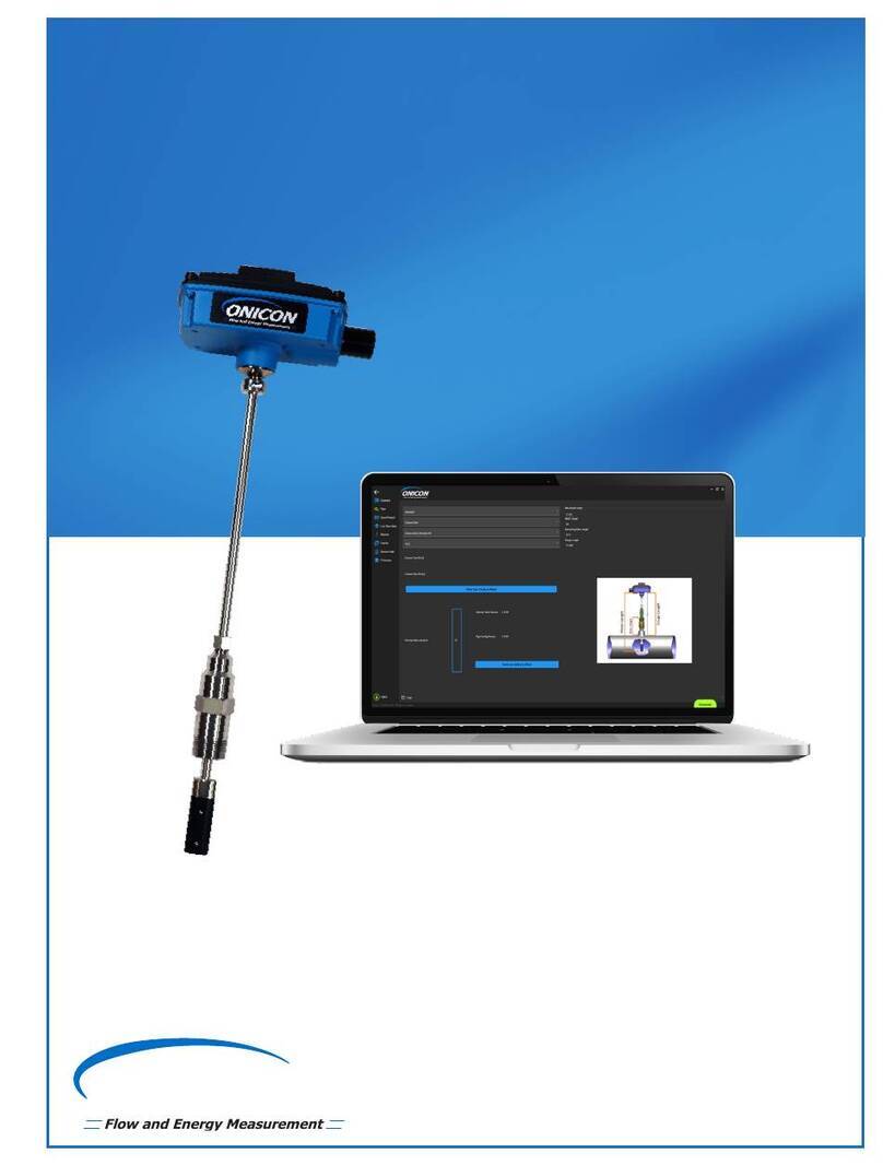
Onicon F-2500 series Operating instructions
Other Onicon Measuring Instrument manuals
Onicon
Onicon D-1401 Operating instructions
Onicon
Onicon F-4600 Series Operating instructions
Onicon
Onicon F-4600 Series Operating instructions
Onicon
Onicon FP-4400 Original operating instructions
Onicon
Onicon Fox Thermal FT2A User manual
Onicon
Onicon D-100 User manual
Onicon
Onicon SeaMetrics AG90 User manual
Onicon
Onicon SYSTEM-30 Operating instructions
Onicon
Onicon D-100 User manual
Onicon
Onicon System-10 BTU Meter User manual
Onicon
Onicon F-1100 Series User manual
Onicon
Onicon F-1000 SERIES User manual

Onicon
Onicon FT-3400 Operating instructions
Onicon
Onicon System-10 BTU Meter User manual
Onicon
Onicon SYSTEM-20 Operating instructions
Onicon
Onicon System-10 BTU Meter Operating instructions
Onicon
Onicon Fox Thermal FT1 User manual
Onicon
Onicon FT-3400 Operating instructions
Onicon
Onicon F-2600 Series Operating instructions
Onicon
Onicon SeaMetrics EX90 User manual
Popular Measuring Instrument manuals by other brands

Powerfix Profi
Powerfix Profi 278296 Operation and safety notes

Test Equipment Depot
Test Equipment Depot GVT-427B user manual

Fieldpiece
Fieldpiece ACH Operator's manual

FLYSURFER
FLYSURFER VIRON3 user manual

GMW
GMW TG uni 1 operating manual

Downeaster
Downeaster Wind & Weather Medallion Series instruction manual

Hanna Instruments
Hanna Instruments HI96725C instruction manual

Nokeval
Nokeval KMR260 quick guide

HOKUYO AUTOMATIC
HOKUYO AUTOMATIC UBG-05LN instruction manual

Fluke
Fluke 96000 Series Operator's manual

Test Products International
Test Products International SP565 user manual

General Sleep
General Sleep Zmachine Insight+ DT-200 Service manual


