JK Audio Innkeeper PBX User manual

JK Audio
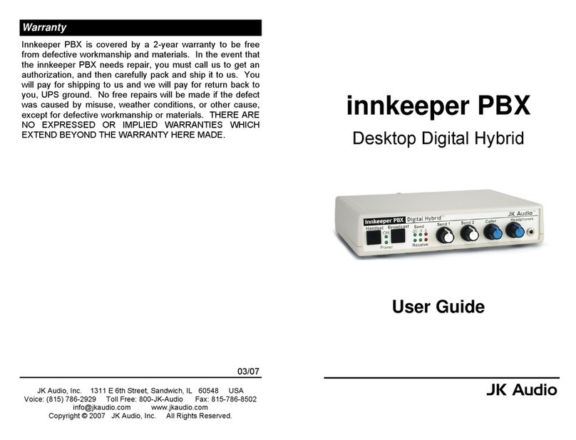
Innkeeper PBX
Desktop Digital Hybrid
User Guide

2 3
Innkeeper PBX will allow you to send and receive audio
through your multi-line PBX, ISDN or analog telephone.
While this may seem like a simple task that any telephone can
do, the challenge is getting the best quality audio from such a
limited audio path.
What is a Digital Hybrid?
The Innkeeper PBX digital hybrid connects audio signals to
and from the handset side of a telephone without the
variations in quality found with analog hybrids. The main
function of a hybrid is to bring in the callers voice from the
phone line, as clear and clean as possible. In the real world,
when you send your voice down the telephone line it has a
tendency to bleed over into the caller’s audio. The hybrid
must adapt to the audio signals from the telephone in order to
properly separate transmit and receive audio. We use a 16
bit DSP to continuously monitor the audio signals from the
telephone to deliver excellent separation. Our dual-
convergence algorithm can achieve excellent trans-hybrid
loss, also known as "separation".
Ready to go?
The Innkeeper PBX controls and connectors are clearly
marked and ready for operation. The feature diagram will
help you pinpoint any minor questions that you may have. If
this is your first exposure to a hybrid, we suggest that you
read the entire manual to allow you to take advantage of all
these features.
Any Questions?
Before you pick up the phone... Please thumb through the
rest of this manual. You might find those deep technical
questions are covered on later pages.
1 2 3 4 5 6
7 9
8 10 11
12 13 14 15 16 17 18 19 20
Introduction Features

4
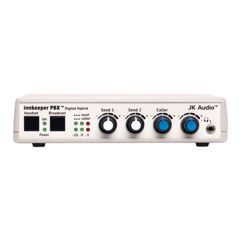
Handset Button - Press this button to use the handset as
if you were on a normal call.
Broadcast Button - Press this button to disable the
handset and activate the Innkeeper PBX for use as a
digital hybrid.
Send 1 Level - Adjusts the signal level that you are
sending down the telephone line, through the female
XLR input.
Send 2 Level - Adjusts the signal level that you are
sending down the telephone line, through the 3.5mm mini
jack input.
Caller Level - Adjusts the level of the signal coming in
from the telephone line, going out the output jacks.
Headphone Level - Adjusts the signal level coming from
the 3.5mm front panel headphone jack.
ON LED - Lit when you are on line with a call using the
digital hybrid within the Innkeeper PBX.
Power LED - Lit when unit is plugged in and receiving
power.
Send LEDs - Displays the signal level going out to the
telephone line.
Receive LEDs - Displays the signal level coming from the
phone line, after the DSP.
Headphones - The 3.5mm stereo headphone jack
contains a mix of both the send input audio and the caller
audio.
Handset Jack - Connect your telephone handset to this
jack.
Phone Jack - Connect this jack to the handset jack on your
telephone using the supplied handset jumper cable.
Handset Type Selector Switch - Use this switch to select
the correct type of handset microphone that your telephone
uses. A=Electret, B=Carbon, C=Dynamic.
Caller Output - Male balanced XLR output contains the
callers voice.
Send 1 Input - Female balanced XLR input for signals
going into the phone line. Mic or line level input.
Mic / Line switch - Sets the front end sensitivity of the Send
1 XLR jack. Set to Mic if you intend to plug a microphone
directly to the Send jack. Set to Line if you are connecting
to the line or auxiliary output of a mic mixer.
Send 2 Input - 3.5mm mono mini jack input for signals
going into the phone line. Line level.
3.5mm Output - Stereo mini jack output contains send and
receive audio determined by the send 1 and send 2 levels
and the caller level controls. Left channel contains your
local send audio and right channel contains the caller's
audio from the telephone line.
Power Jack - For connection to supplied 9VDC regulated
power supply only.
1.
2.
3.
4.
5.
6.
7.
8.
9.
10.
11.
12.
13.
14.
15.
16.
17.
18.
19.
20.
5
Features (cont) Features (cont)

76
Connecting Cables
Although each application will require a slightly different setup,
standard configuration is as follows:
Handset cable - Connect the supplied RJ-22 handset cable
between the jack marked "Phone" on the back of Innkeeper PBX
and to the handset jack of your telephone.
Handset - Connect your telephone handset to the RJ-22 jack on
the back of the Innkeeper PBX marked "Handset".
Send Audio - Connect a microphone or mixing console output
XLR cable to the Send jack on the Innkeeper PBX. Be sure to
set the Innkeeper PBX mic/line switch to the proper position for
your application.
Caller Audio - Connect the Caller Out jack to a line level input on
your mixing console or recording device.
Power - Connect the supplied DC power supply to the back of
the Innkeeper PBX and then to an AC power outlet.
Your Innkeeper PBX is now ready to take calls.
Innkeeper PBX will disable the telephone handset when you
press the Broadcast button. Use your telephone to place or
screen a call. When you are ready to take the call on Innkeeper
PBX, simply press the Broadcast button. Make sure you do not
put the handset back in it's cradle while you are on a call. This
will still drop the call even though the handset itself is disabled.
If you need to take the call back on your telephone, simply press
the Handset button on Innkeeper PBX. This will disable the
inputs and outputs on Innkeeper PBX and connect your handset
back to the telephone.
Send Signal Level
The Send LEDs display the signal level as it goes out over the
phone line. The goal is to drive the phone line at high enough
levels to avoid phone line noise, but not so loud as to cause
excessive clipping. Adjust the send level control until you see
occasional flashes of the red -3dB peak Send LED. These
flashes should occur during loud speech bursts. If the red LED
stays lit for extended periods you can assume that much of
your speech is being clipped or distorted. In this case you
should back down on the Send volume control for the input that
is causing the clipping.
Receive Signal Level
The receive LEDs display the signal coming from the phone
line and out of the DSP. The Caller level control does not
change what you see on these LEDs. Adjust the Caller level
control to give you the best signal at your equipment.
Headphone Mix
The 3.5 mm headphone jack on the front of Innkeeper PBX is
used for monitoring your call. This stereo jack contains a mix
of both sides of the conversation on each headphone channel.
The levels of this mix are determined by the Send 1 and Send
2 volume controls (for your local audio) and by the Caller
volume control. The overall audio level from this jack is
determined by the Headphones volume control.
The headphone mix allows you to monitor both send and
receive signals. The true power of the Innkeeper PBX is its
ability to separate send and caller audio. To hear this
separation you must listen to the caller output on either the
XLR or 3.5mm output jacks.
Operation Operation (cont)

8
Inputs:
Send 1:
Send 2:
Outputs:
Balanced:
Unbalanced:
Headphone:
Phone Jack:
Handset Jack:
Isolation:
Frequency:
Response
Power:
Size:
Weight:
Balanced Female XLR, 1k ohm, -10 mV RMS
(-35 dBv nom)
Mic/Line pad switch = +4 dBv max
3.5mm mono,20k ohm, 250 mV RMS (-10
dBv nom)
Male XLR, 200 ohm, 500 mV RMS (+4 dBv
max)
3.5mm stereo, 50 ohm, 250 mV RMS (0 dBv
max), Left = send, Right = caller
3.5mm stereo, 8 ohms, 250 mW mixed send
and caller in both channels
RJ22
RJ22
1500 VAC
telephone side 200 Hz - 3600 Hz
120-240 VAC power supply (included)
9 VDC regulated center +
7" x 6" x 1.6" (18 x 15 x 4.2 cm)
2.2 pounds (1 kg)
Specifications
9
Specifications
ABC Selector Switch
Use this switch to select the correct type of handset microphone
that your telephone uses. A=Electret, B=Carbon, C=Dynamic.
Trial and error seems to work best in determining which handset
type to use. Your Innkeeper PBX will only function correctly if
the handset type selector switch is in the correct position. This
switch changes signal level, impedance, and wiring to
accommodate the differences in handset microphone types. In
order to determine the correct position, you must place a call to a
nearby telephone, then try to send audio into the Innkeeper PBX
through the inputs. While doing this, switch between the three
different handset type positions. Choose the position that works
best by monitoring the audio quality and send LED's.
Although not conclusive, the following guidelines may help:
The majority of newer telephones have electret type
microphones and will use the "A" position.
Older telephones that have the round "screw type" handsets
contain carbon microphones and use the "B" position.
Many Radio Shack ,Panasonic , and Nortel telephones have
dynamic microphone types and use the "C" position.
R R R

10 11
Repairs to this telephone equipment can only be made by the
manufacturer or its authorized agents or by others who may be
authorized by the FCC. For repair procedures, follow the
instructionsoutlinedunderthewarrantysectionofthemanual.
4. Rightsofthetelephonecompany
If telephone equipment is causing harm to the network, the telephone
company may temporarily discontinue your telephone service. If
possible, they'll notify you before they interrupt service. If advanced
notice isn't practical, you'll be notified as soon as possible. You'll be
given the opportunity to correct the problem, and you'll be informed of
yourrighttofileacomplaintwiththeFCC.
Your telephone company may make changes in its facilities,
equipment, operations or procedures that could affect the proper
functioning of your JK Audio product. If such changes are planned,
you'llbenotified.
If this telephone equipment is to be used with a telephone that is
leased or owned by another party, permission to connect this
telephone equipment to their telephone must first be obtained.
FCC Registration (cont)
FCC Registration
1. Connectionandusewiththenationwidetelephonenetwork
The FCC requires that you connect this telephone equipment to
the national telephone network through a FCC registered
telephone.
This equipment may not be used with Party Line Service or Coin
TelephoneLines.
2. Informationforthetelephonecompany
Upon request from your local telephone company, you are
requiredtoprovidethefollowinginformation:
a) The "line" to which you will connect the telephone equipment
(thatis,yourtelephonenumber),and
b)Thetelephoneequipment'sFCCregistrationnumber. Thiscan
befoundonthebottomofyourtelephoneequipment.
3. RepairInstructions
If it is determined that your telephone equipment is
malfunctioning, the FCC requires that it not be used and that it
be unplugged from the modular outlet until the problem has been
corrected.
Your new JK Audio product has been registered with the Federal
Communications Commission (FCC). This product complies with the
standards in Part 68 of the FCC rules. The FCC requires us to provide the
followinginformation:.
This equipment has been tested and found to comply with the limits for a Class
A digital device, pursuant to Part 15 of the FCC Rules. These limits are
designed to provide reasonable protection against harmful interference when
the equipment is operated in a commercial environment. This equipment
generates, uses, and can radiate radio frequency energy and, if not installed
and used in accordance with the instruction manual, may cause harmful
interference to radio communications. Operation of this equipment in a
residential area is likely to cause harmful interference in which case the user
will be required to correct the interference at his own expense.
Changes or modifications not expressly approved by JK Audio can void the
user's authority to operate the equipment.
FCC Part 15 Compliance
6/03
JK Audio
Innkeeper PBX is covered by a 2-year warranty to be free from
defective workmanship and materials. In the event that the
Innkeeper PBX needs repair, you must call us to get an
authorization, and then carefully pack and ship it to us. You will
pay for shipping to us and we will pay for return back to you, UPS
ground. No free repairs will be made if the defect was caused by
misuse, weather conditions, or other cause, except for defective
workmanship or materials. THERE ARE NO EXPRESS OR
IMPLIED WARRANTIES WHICH EXTEND BEYOND THE
WARRANTY HERE MADE.
Warranty
Other manuals for Innkeeper PBX
4
Other JK Audio PBX manuals