JLA D170 User manual
D170 Parts Manual
Phase 7
JLA Part No. 450597
JLA Limited
Meadowcroft Lane, Halifax Road
Ripponden
West Yorkshire, England
HX6 4AJ
Telephone: 01422 822282 / Fax: 01422 824390

FOR YOUR SAFETY
Do not store or use gasoline
or other flammable vapors
and liquids in the vicinity of
this or any other appliance.
POUR VOTRE SÉCURITÉ
Ne pas entreposer ni utiliser d’essence
ni d’autres vapeurs ou liquides
inflammables à proximité de cet
appareil ou de tout autre appareil.
Retain This Manual in a Safe Place for Future Reference
This product embodies advanced concepts in engineering, design, and safety. If this product is properly
maintained, it will provide many years of safe, efficient, and trouble free operation.
Only qualified technicians should service this equipment.
OBSERVE ALL SAFETY PRECAUTIONS displayed on the equipment or specified in the installation
manual included with the dryer.
The following “FOR YOUR SAFETY” caution must be posted near the dryer in a prominent location.
“IMPORTANT NOTE TO PURCHASER”
Information must be obtained from your local gas supplier on the
instructions to be followed if the user smells gas. These instructions
must be posted in a prominent location near the dryer.
We have tried to make this manual as complete as possible and hope you will find it useful. The
manufacturer reserves the right to make changes from time to time, without notice or obligation, in prices,
specifications, colors, and material, and to change or discontinue models. The illustrations included in
this manual may not depict your particular dryer exactly.
IMPORTANT
For your convenience, log the following information:
DATE OF PURCHASE _____________________________________________________________ MODEL NO. ________________________
RESELLER’S NAME _________________________________________________________________________________________________
Serial Number(s) __________________________________________________________________________________________________
___________________________________________________________________________________________________________________
___________________________________________________________________________________________________________________
Replacement parts can be obtained from your reseller or JLA. When ordering replacement parts from the
factory, you can FAX your order to JLA at 1 422-824390 or telephone your order directly to the JLA Parts
Department at 1 422-822282. Please specify the dryer model number and serial number in addition to the
description and part number, so that your order is processed accurately and promptly.
D170

Control Door Assembly .................................................................................................................................... 4
Phase 7 Non-Coin Microprocessor Control Panel Assembly ....................................................................... 5
Front Panel/Main Door Assemblies ............................................................................................................ 6, 7
Main Door Switch Assembly ............................................................................................................................ 8
Tumbler Assembly ............................................................................................................................................ 9
Phase 7 Rotational Sensor Assembly .......................................................................................................... 10
Lint Door Assembly ........................................................................................................................................ 11
Lint Drawer/Lint Drawer Switch Box Assemblies for Models Mfd. as of February 1, 2003 ...................... 12
Lint Drawer/Lint Drawer Switch Box Assemblies for Models Mfd. prior to February 1, 2003 .................. 13
Fan (Squirrel Cage) Shaft Mount Assembly ................................................................................................. 14
Blower Motor Mount Assembly ...................................................................................................................... 15
Microprocessor Temperature Sensor Bracket Assembly ........................................................................... 16
Drive Shaft Assembly ..................................................................................................................................... 17
Idler Shaft Assembly ...................................................................................................................................... 18
Speed Reducer Shaft Assembly ................................................................................................................... 19
Totally Enclosed, Non-Venting Drive Motor Assembly ................................................................................. 20
CE Hot Surface Ignition Burner Assembly ................................................................................................... 21
Direct Spark Ignition Burner Assembly ................................................................................................... 22, 23
Sail Switch Assembly ..................................................................................................................................... 24
Air Jet Assembly ............................................................................................................................................. 25
Microprocessor Reversing Contactor Mounting Panel Assembly for 208-240V Transformers ......... 26, 27
Microprocessor Reversing Contactor Mounting Panel Assembly for 380-416V Transformers ......... 28, 29
Microprocessor Reversing Contactor Mounting Panel Assembly for 460-480V Transformers ......... 30, 31
Steam Damper Assembly for Steam Models Only ...................................................................................... 32
Pneumatic Valve Assembly for Gas Models Only ........................................................................................ 33
Pneumatic Valve Assembly for Steam Models Only .................................................................................... 34
Top Console Assembly .................................................................................................................................. 35
S.A.F.E. Temperature Probe Assembly ........................................................................................................ 36
S.A.F.E. Solenoid Assembly for Models Mfd. as of September 23, 2004 .................................................. 37
S.A.F.E. Solenoid Assembly .......................................................................................................................... 38
Back Guard Assemblies ................................................................................................................................ 39
Table of Contents
4JLA Limited 450597-2
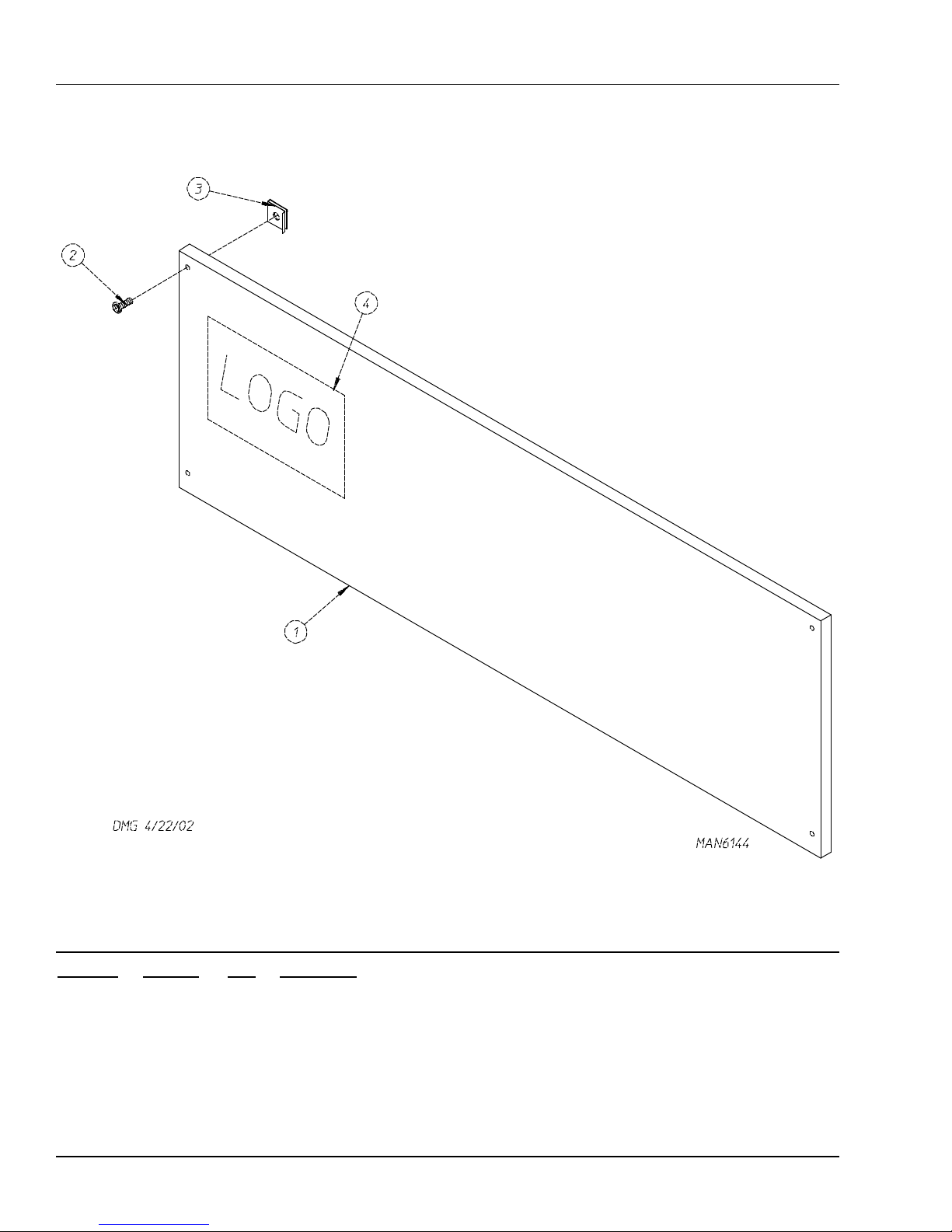
Control Door Assembly
Illus. No. Part No. Qty. Description
1* 883256 1Phase 7 Control Door (gas)
883322 1Phase 7 Control Door (steam)
2150314 4#10-32 x 1/2” TORX Screw
3154011 4#10-32 Multi-Thread U-Nut
4** ——— 1Logo
*Specify color when ordering.
** Contact reseller for logo.

450597-2 Telephone: 01422 822282 / Fax: 01422 824390 5
Phase 7 Non-Coin Microprocessor Control Panel Assembly
Illus. No. Part No. Qty. Description
1112577 1Phase 7 Non-Coin Keypad
(for models mfd. as of September 11, 2004)
112571 1Phase 7 Non-Coin Keypad
(for models mfd. prior to September 11, 2004)
2850980 1Phase 7 Microprocessor Controller (computer) Panel Only
822754 1Phase 7 Non-Coin Reversing Microprocessor Controller (computer)
Control Panel Assembly Complete
(includes illus. nos. 1 through 7)
3887005 1Phase 7.2.2 Non-CoinMicroprocessor Controller (computer)
with Sensor Activated Fire Extinguishing System Only
(for models mfd. as of December 3, 2003)
887002 1Phase 7.2.1 Non-CoinMicroprocessor Controller (computer)
with Sensor Activated Fire Extinguishing System Only
(for models mfd. prior to December 3, 2003)
4150005 2#6-32 x 3/4” Phillips Round Head Machine Screw
5153010 2#6 Star Washer
6136016 15 amp Fuse
7136097 1500 mA Fuse
6JLA Limited 450597-2
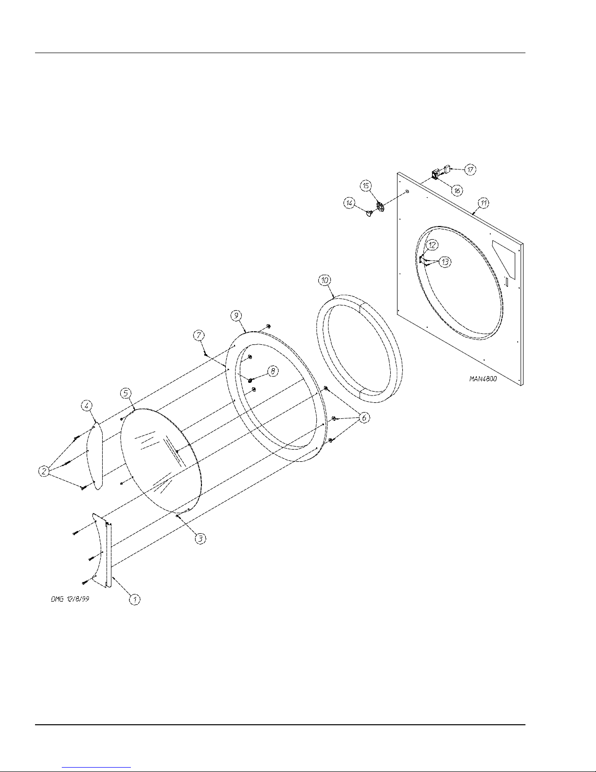
Front Panel/Main Door Assemblies

450597-2 Telephone: 01422 822282 / Fax: 01422 824390 7
Illus. No. Part No. Qty. Description
1881685 1White Main Door Hinge
882296 1Coral Wrinkle Blue Main Door Hinge
2881740 61/4-20 x 5/8” White Carriage Bolt
881739 61/4-20 x 5/8” Coral Wrinkle Blue Carriage Bolt
3151012 1#10-32 White Acorn Nut
4881688 1White Main Door Handle
881737 1Blue Main Door Handle
5102214 130” Door Glass
170730 1Door Glass Adhesive (10.3 oz. cartridge)
6881806 61/4-20 White Free Spin Wash Nut
882293 61/4-20 Coral Wrinkle Blue Free Spin Wash Nut
7150120 1Main Door Latch Screw
(#10-32 dome hex head screw)
8151010 1#10-32 Acorn Nut
9881689 1White Main Door Assembly Complete
(includes illus. nos. 2 through 10)
881761 1Coral Wrinkle Blue Main Door Assembly Complete
(includes illus. nos. 2 through 10)
881966 1White Main Door Ring
882305 1Coral Wrinkle Blue Cold Rolled Steel Large Main Door Ring
10 882411 1Extruded Steel Door Gasket
11 882503 1White Front Panel Assembly
(includes illus. nos. 1, 15, and 16)
882504 1Coral Wrinkle Blue Front Panel Assembly
(includes illus. nos. 1, 15, and 16)
12 170330 1Friction Door Latch
13 154215 25/32” Pop Rivet
14 122351 1“EMERGENCY STOP” Push-Pull Button
15 122419 1“EMERGENCY STOP” Nameplate
16 132387 1Normally Closed Contact Block
17 132395 1Normally Closed Contact Block with Base
Front Panel/Main Door Assemblies

8JLA Limited 450597-2
Main Door Switch Assembly
Illus. No. Part No. Qty. Description
1150006 2#6-32 x 7/8” Phillips Pan Head Machine Screw
2152013 2#6-32 Hex Nut
3153010 2#6 Star Washer
4137005 1Single-Pole Door Switch
5150443 41/4-20 x 3/4” Stainless Steel Cap Screw
6881687 1White Main Door Switch Housing Only
881695 1Blue Main Door Switch Housing Only
881702 1White Main Door Switch with Housing Assembly
(includes illus. nos. 1 through 4 and 6)
881700 1Blue Main Door Switch with Housing Assembly
(includes illus. nos. 1 through 4 and 6)
7150443 21/4-20 x 3/4” Stainless Steel Cap Screw
8881441 1White Bottom Hinge Block
881735 1Blue Bottom Hinge Block
9881440 1White Top Hinge Block
881736 1Blue Top Hinge Block
10 153031 1Nylon Washer
450597-2 Telephone: 01422 822282 / Fax: 01422 824390 9
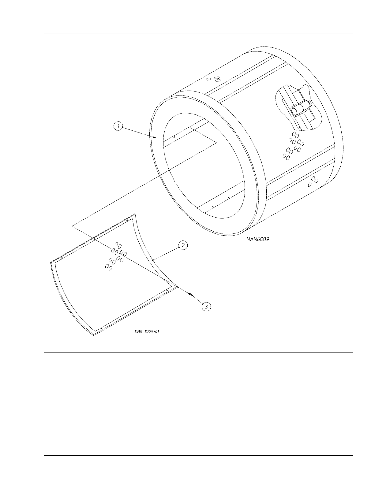
Illus. No. Part No. Qty. Description
1835402 1Stainless Steel Tumbler Assembly Complete
(for models mfd. as of November 10, 2003)
(includes illus. nos. 1 through 3)
835375 1Tumbler Assembly Complete
(for models mfd. prior to November 10, 2003)
(includes illus. nos. 1 through 3)
2390329 4Stainless Steel Perforated Tumbler Panel
(for models mfd. as of November 10, 2003)
883578 4Perforated Tumbler Panel
(for models mfd. prior to November 10, 2003)
3150118 24 1/4-20 x 1/4” Phillips Pan Head Screw
Tumbler Assembly

10 JLA Limited 450597-2
Phase 7 Rotational Sensor Assembly
Illus. No. Part No. Qty. Description
1819064 1Tumbler Shaft Support Assembly Complete
(includes illus. nos. 1 through 8)
835339 1Tumbler Shaft Support Bracket
2102394 2Tumbler Friction Pad
3153005 63/8” Lock Washer
4150619 23/8-16 x 1” Tap Bolt
5153004 83/8” Flat Washer
6180018 24” x 1-1/2” Hi-Impact Wheel
7819046 1Tumbler Adjustment Plate
8819065 1Tumbler Shoulder Screw
9822735 1Phase 7 Rotational Sensor Assembly
10 152005 43/8-16 Hex Nut
11 323433 2Rear Wheel Shim
Table of contents
Other JLA Dryer manuals


Popular Dryer manuals by other brands

Bosch
Bosch WTA79200GB Installation and operating instructions

Amana
Amana W10233410A Use and care guide

Miele
Miele TWH 780 WP operating instructions

Asko
Asko T760 user guide

Alliance Laundry Systems
Alliance Laundry Systems 25 Series Original instructions

Bosch
Bosch Logixx 10 WTB76556GB Instruction manual and installation instructions


Indesit
Indesit IDV 75 instruction manual

Infiniton
Infiniton SD-DG85C manual

BOMANN
BOMANN WT 5019 instruction manual

Alliance Laundry Systems
Alliance Laundry Systems TMB795C Installation

Asko
Asko T793C operating instructions

Kenmore
Kenmore 8041 - 5.8 cu. Ft. Capacity Electric Dryer installation instructions